Baibaswata Mohapatra1 , Sovan Mohanty2*, Md. Rashid Ansari3 , and Diptimayee Dash4
1.3Department of Electrical, Electronics and Communication Engineering, Galgotias University, Greater Noida, U.P., India 2 Department of Electronics and Communication Engineering, SRMS College of Engineering and Technology, Bareilly, U.P., India 4 Department of Electrical and Electronics Engineering, Galgotias College of Engineering and Technology, Greater Noida, U.P., India
writetobm@gmail.com, mohanty.sovan@gmail.com, rashidvns@gmail.com, dash.diptimayee@gmail.com
Abstract: In this paper an ultra-broadband printed antenna is reported for personal communication system applications on a finite ground plane. This proposed miniaturized antenna produces a 10 dB return loss bandwidth of 136.13% with a stable gain of 3.425 dBi. The radiation bandwidth is broadband in nature, while impedance bandwidth is much greater than radiation and gain bandwidth. This antenna supports circular polarization with an axial ratio of less than 3 dB over the measured operating frequency from 3.8 GHz to 20 GHz. An E-U-shaped slot is etched on the elliptical-shaped radiating patch to balance the effect of reactance and to create multiple resonances. Behind the substrate, a rectangular slot with corner truncation is etched on the finite ground plane to enhance the matching profile and the effective resonance. The proposed antenna is suitable for dedicated short-range personal communication system applications while supporting intelligent transport systems, notebooks, smart homes, and wearable devices.
Keywords: Ultra broadband printed antenna, Personal communication system, Finite ground plane, Ultra wide band antenna
1. Introduction
The ultra-broadband antenna separates from the UWB antenna in terms of its spectral density and low power emission into narrow frequency intervals [1]. It has various potential applications ranging from the personal communication system (PCS), jammers, ultra-short radar systems, and the detection of complicated buried objects. The spreading of the energy over a wide band, the amount of energy coupled into the system is reduced by the coupling bandwidth to that of ultra broad bandwidth. Further, the microstrip antenna technology provides the suitable solution for non-electrical characteristics. However, in terms of electrical performance, it brings challenges like narrow bandwidth, low co and cross-polarization ratio, and poor power handling capabilities to satisfy radio and radar equations. The inherent limitation of the micro-strip patch antenna is its narrow impedance bandwidth due to its dominant reactive parameters and non-linear capacitive structure. The capacitive structure promulgates a storage field rather than the desired radiative field. Therefore, investigation in enhancing impedance bandwidth with varying degrees of success is one of the research areas among antenna designers. Accurate estimation of the propagation constant, characteristics impedance, and wave impedance results in the effective prediction of resonant resistance and resonant frequency. On a fundamental note, an enhancement of bandwidth obtained by making the antenna an efficient resonant radiator. The bandwidth broadening technique used here is the generation of coplanar and multiple resonances [2]. The coupling between multiple resonances should be made tight for the overlapping of the impedance bandwidth. Different parts of the designed structure radiate with relative magnitude and phase at different frequencies. The presence of the parasitic elements alters the phase center and the field patterns. The slot of different dimensions will create a staggering effect to tune the entire band of frequencies. Enhancement of impedance bandwidth occurs due to the presence of
Received: October 14th, 2022. Accepted: May 16th, 2023
DOI: 10.15676/ijeei.2023.15.2.1
a finite ground plane. However, a trade-off is associated with the radiation efficiency and the antenna gain. It has been observed that most of the perturbation procedures and feeding techniques used to design planar CP antennas [3], offered narrow impedance bandwidth. Many slot-based antennas have been proposed using embedded feed asymmetry or slot asymmetry [4– 13] to design UWB circularly polarized antennas. Asymmetry adjusts the magnitude as well as 90 degree phase shifted E-field components. The double-Y-shape slot is presented in [5] to achieve circular polarization. Wideband antennas based on the asymmetrical slot are presented in [6–7]. Spiral arm-shaped feeds with CP antennas are discussed in [8, 9]. Most of the CP antennas proposed offered wide bandwidth but relatively bulkier in size [10–12]. Different antenna structures for UWB circularly polarized patch antenna design have been proposed [13- 17].
In this paper, an ultra broad band printed antenna with E-U geometry based tapered slot is proposed and investigated. A detailed investigation of the resonant frequency and output characteristics are carried out with a trade-off between ultra impedance bandwidth and desired output characteristics. The antenna possesses slot asymmetry to create the staggering effect to improve the bandwidth and circular polarization. The parametric analysis of the ultra-broadband antenna is discussed in Section 2. In this section, two steps are included. The first step includes only an elliptical-shaped patch without a slot. The second step includes an elliptical-shaped patch with E-U shaped slot. In section 3 simulated and experimental results are presented. Section 4 discusses the conclusions of the work.
2. Antenna Design Parameters and Implementation
The proposed elliptical shaped and E-U slotted elliptical-shaped ultra broad band printed antenna is shown in Figure 1 and Figure 2. The antenna is placed on the top of the Rogers RT/ Duroid 5880. The dimension of the substrate is 38 mm×40 mm×1.54 mm with εr equals to 2.5. A 2.92 mm connector is used which can provide support up to 40 GHz with the impedance of 50Ω. The connector D360B50H01-118 (Microwave Town Company) is used from 2 GHz to 20 GHz frequency band for the antenna measurement. This finite shape takes around 30% of the total finite ground plane and therefore left enough space for RF circuitry to get embedded. The elliptical-shaped patch element is having E and U slot feed through a quarter-wavelength line. For the chosen specification elliptical-shaped patch dimensions are calculated using transmission line theory. A rectangular slot with a truncated corner on the ground plane is used to concentrate current to the edge of the finite ground. It will enlarge the area of the current path that affects the characteristics of the magnetic field. Therefore, the electromagnetic field pattern formed at the bottom of the antenna alters the resonant phenomenon in the patch with the association of the finite ground plane. The resultant hybrid mode will enhance the impedance matching profile and initiate an axial ratio that can support circular polarization. Simulation and optimization are carried out with HFSS 14.0 software. The antenna dimension is 38×40×1.6 mm3 . The fabricated view is shown in figure 3 (a) & 3 (b).
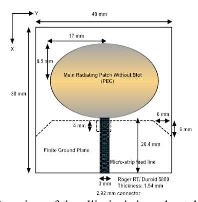
Figure 1. Top view of the elliptical shaped patch without slot
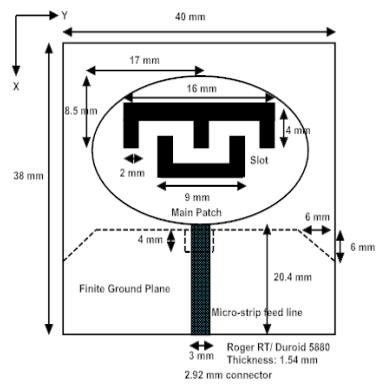
Figure 2. Top view of the elliptical shaped radiating patch with slot
A. Elliptical Shaped Patch without Using E-U Slot
Figure 1 shows the elliptical-shaped radiating patch with the finite ground plane. This structure does not have any slot on the patch. The elliptically shaped radiating patch is made up of Copper as perfectly electrical conductor (PEC) with major axis of 34 mm and minor axis of 17 mm. A micro-strip feed line of length 20.4mm and width 3mm is used to connect to the source with 2.92 mm connector. At the bottom portion of the substrate a finite ground plane with a notch at the top is used to reduce the reactive effect so as to mitigate the excessive capacitance effect. It will help to enhance the bandwidth. Further the infinite ground plane will help to provide effective impedance matching. The simulated return loss is shown in Figure 2. The antenna shows multiband characteristics from 4 GHz onwards up to 22 GHz, rather than ultra-wideband response. The output characteristics for this multiband response are found to be inconsistent with arbitrary radiation patterns. The cross and co-polarization are below 10 dB at a certain angle which makes the antenna an inefficient radiator and receiver.
B. E-U Slotted Elliptical Shaped Patch
Figure 2 shows the E-U slotted elliptical-shaped ultra-broadband printed antenna indicating the dimension of the slot over the patch. Here rectangular and corner truncation is used for impedance matching. Optimized values of proposed design specifications are given in Table 1.
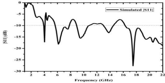
Figure 3. Return loss of the antenna without slot
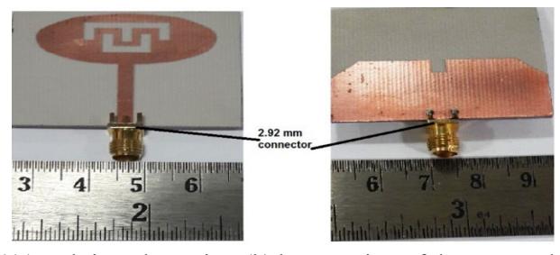
Figure 4(a). Fabricated top view (b) bottom view of the proposed antenna.
3. Calculation of Resonant Frequency
The fringing field effect of the radiated patch and dielectric substrate will play a significant role while calculating the resonant frequency. The coupling effect and the driven micro-strip feed line influence the resonating conditions. The elliptical patch will produce circular polarization if the eccentricity is small. The thickness of the substrate is lesser than the wavelength in the dielectric. Therefore the field of the dielectric doesn't vary w.r.t z-axis. The effective dielectric constant \((\varepsilon_{eff})\) is reported in terms of a function 'F' which depends on \(\varepsilon_r\) and the ratio of aperture dimensions to the substrate thickness of the micro-strip antenna [18].
\[\varepsilon_{\text{eff}} = \frac{\varepsilon_r + 1}{2} + \frac{\varepsilon_r - 1}{2} F, \ 0 < F < 1 \tag{1}\]
F is derived from the ratio of fringing area on the plane to the area of the patch. \[F = 1 - \frac{c_n \varepsilon_r}{\varepsilon_{r-1}} \times \left( \frac{Fringing \ area \ on \ the \ plane \ of \ the \ patch}{Area \ of \ the \ microstrip \ patch} \right)\] where \(C\) is a coefficient to be determined to find \(E\) and \(C > 0\).
where \(C_n\) is a coefficient to be determined to find F and \(C_n > 0\).
The fringing area of the elliptical antenna is:
\[\pi(a+d)(b+d) - \pi ab = \pi d(a+b+d) \tag{3}\]
The semi-major axis is 'a', semi-minor axis is 'b' and the width of the fringing field is 'd'. The effective dielectric permittivity will be:
\[\varepsilon_{eff} = \varepsilon_r - \frac{C_n \varepsilon_r}{2} \left( \frac{d}{a} + \frac{d}{b} + \frac{d^2}{ab} \right)\] \[Area_{ellipse} = \sqrt{Area_{Circle1} + Area_{Circle2}} = \pi a_{eq} b_{eq}\] (5)
\[Area_{ellipse} = \sqrt{Area_{circle1} + Area_{circle2}} = \pi a_{ea} b_{ea}\] (5)
\(a_{eq}\) is the equivalent semi-major length and \(b_{eq}\) is the equivalent semi-minor length.
\[a_{eq} = \left[ a^2 + \frac{2da}{\pi \varepsilon_{eff}} \left\{ ln \left( \frac{a}{2d} \right) + \left( 1.41 \varepsilon_{eff} + 1.77 \right) + \frac{d}{a} (0.268 \varepsilon_{eff} + 1.65) \right\} \right]^{1/2}\] (6)
\[b_{eq} = \left[ b^2 + \frac{2db}{\pi \varepsilon_{eff}} \left\{ ln \left( \frac{b}{2d} \right) + \left( 1.41 \varepsilon_{eff} + 1.77 \right) + \frac{d}{b} \left( 0.268 \varepsilon_{eff} + 1.65 \right) \right\} \right]^{1/2}\] (7)
As the height of the dielectric is much lesser than the wavelength of operations \((h \ll \lambda)\), therefore the propagation constant will be:
\[k_{m,n} = 2\pi f \sqrt{\varepsilon_0 \mu_0 \varepsilon_{dyn}} \tag{8}\]
where the sub-script described the mode along the major and minor axis and \(\varepsilon_{dyn}\) is the changing permittivity of the medium.
Assuming the radial current at the perimeter the boundary condition will be:
\[J_{0m}'\left(k_{mn}C, \frac{1}{e}\right) = 0 \text{ (Odd mode)}\] (9)
\[J'_{em}\left(k_{mn}C, \frac{1}{e}\right) = 0 \text{ (Even mode)}\] (10)
By replacing the aperture dimension and \(\varepsilon_r\) with their effective value, the resonant frequency will
be [19]:
\[f_{r} = \frac{C_{0}k_{mn}C}{2\pi a \epsilon \sqrt{\epsilon_{dyn}}}\]
(11)
4. Results and Discussion
Here optimization of the performance of single fed circularly polarized UBP antenna is carried out. The little-known resonant currents on the boundary of the patch are expanded with domain basis functions whereas the electric field at the interior side can be expanded with piecewise sinusoidal basis function. The patch was overexcited whereas the ground plane was under excited with reduced Q-factor. Because of the fine geometric plane this device is very sensitive and has numerous critical parameters like input return loss and radiation pattern control. The E-shaped and U-shaped slot-loaded patch provides coupled controlled resonator structure. The two folded slot provides strong impedance matching both for the higher-order mode and the
dominant mode. Fig. 6 shows the return loss of the simulated and fabricated slotted ultra broad band printed antenna. The simulated and the measured impedance bandwidth matches. The measured impedance bandwidth is 136.13% (3.8 – 20 GHz). Fig. 5 shows the distributed surface current density (J) frequencies. There is formation and interaction of multiple dipoles having resonant frequency slightly above, slightly below nominal center frequency to achieve phase quadrature. However, the phase shift is very sensitive to frequency. Here two orthogonal modes are excited by using an elliptically shaped patch with notches. The main patch has a trimmed corner. It has been observed that 'Jmax' is obtained around the edges boundary of E-U slots and the elliptical patch. Figure 7 describes the simulated and measured output radiation pattern along the E-plane and H- plane within the impedance bandwidth at 4 GHz, 8.1 GHz, and 10.12 GHz. It shows a stable radiation pattern and low cross-polarization. The axial ratio of E- field along major axis and the minor axis of the radiation pattern is found to be less than 3dB which implies circular polarization.
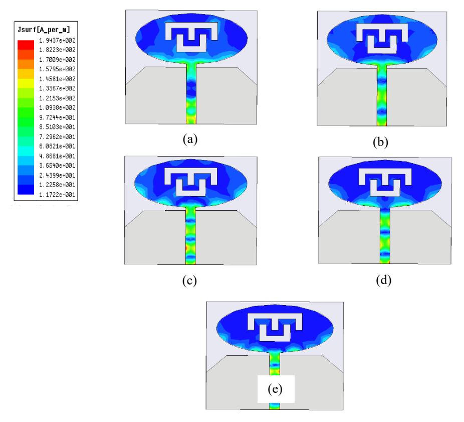
Figure 5. Simulated distributed electric current density (a) at 4 GHz (b) at 8.1 GHz (c) at 10.12 GHz (d) at 12.3 GHz (e) at 20 GHz.
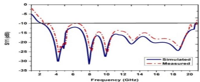
Figure 6. Return loss of the proposed E-U slotted ultra broad band printed antenna
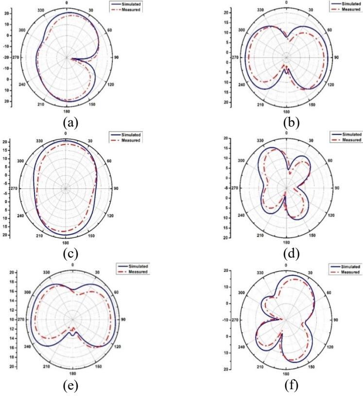
Figure 7. Radiation pattern (a) E-plane at 4 GHz (b) H-plane at 4 GHz (c) E-plane at 8.1 GHz (d) H-plane at 8.1 GHz (e) E-plane at 10.12 GHz and (f) H-plane at 10.12 GHz.
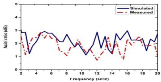
Figure 8. Measured and simulated axial ratio of the proposed antenna
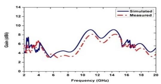
Figure 9. Plot of gain versus frequency
| Reference No. | Parameters | |||
| Centre Frequencies (GHz) | Bandwidth (GHz) | Gain (dBi) | Polarization | |
| Ref. [3] | 3.8, 8 | 7.6 | 3.8 | Circular |
| Ref. [5] | 3.5, 5.2, 6.4 | 3.5 | 8.5 | Circular |
| Ref. [7] | 3.2, 5.2 | 3.7 | 3.1 | Circular |
Proposed work 4, 8.1, 10.12, 12.3, 20 18 8.2 Circular
Table 1. Comparison of recently published work with proposed work
The antenna achieves a high peak gain of 6.2 dBi, 5dBi, 7.2 dBi, and 8.2dBi at 4 GHz, 8.1 GHz, 10.12 GHz, and 20 GHz respectively. Some parameters of the proposed work are compared with recently published literature and shown in Table 1. It is found that the radiator has wide bandwidth, circular polarization with relatively high gain. The gain of [5] is greater than the proposed work but with less bandwidth. At different frequencies, the electrical size of the patch controls the field patterns and gain. Fig. 8 shows the measured and simulated axial ratio of the proposed antenna. Ideally, CP has an axial ratio of 0dB but axial ratio up to 3dB is considered under CP. Fig. 9 shows the relationship between gains versus the entire operating frequency interval. This antenna provides a consistent gain stability of 8 dBi from 10 GHz to 15 GHz and an average gain of 3.425 dBi over the operating band.
There are certain fundamental limitations associated with this design. The induced surface wave propagation will produce diffraction, refraction at the boundary of the dielectric. It results high cross-polarization and increment in the side lobes. The use of a single substrate both for placing the radiating elements and the nonradiating transmission line network is indeed quite contradictory. The longer patch length creates cross-polarization due to the generation of higherorder mode. Therefore this design creates a window of opportunity to expand the investigation and design.
4. Conclusion
An E-U slotted elliptical-shaped circular polarized ultra-broadband printed antenna suitable for personal communication system applications is proposed. This robust low-profile design can accommodate various wireless interfaces by operating over ultra-wide frequencies of 3.8 to 20 GHz with impedance bandwidth of 136.13% and an axial ratio below 3 dB. It provides a maximum stable gain of 8 dBi from 10 GHz to 15 GHz. It will support 4G and is suitable for S, C, X, and Ku bands of frequencies in applications such as wearable devices, notebooks, smart homes, etc. Broad bandwidth may further be realized and improved by genetic algorithms having a trade-off with the complexities and criticality.
5. References
- [1]. First report and order on ultra-wideband technology. Washington, DC: FCC; 2002.
- [2]. Mohanty S., and Mohapatra, B. "Printed Slot Wideband Rectangular Dielectric Resonator Antenna," Innovations in Electrical and Electronic Engineering, Lecture Notes in Electrical Engineering 661, https://doi.org/10.1007/978-981-15-4692-1_44.
- [3]. Tripathi S, Pathak N.P. and Parida, M. "Design of a planner antenna for vehicle tracking using DSRC". In proceedings of 3rd conference of Transportation Research Group of India (3rd CTRG); 2015; 1-10.
- [4]. Malik J, Patnaik A, Kartikeyan MV. "Novel printed MIMO antenna with pattern and polarization diversity". IEEE antennas and wireless propagation letters. 2015; 14:739-742.
- [5]. Pratap LB, Kundu D, Mohan A. "Planar microstrip‐fed broadband circularly polarized antenna for UWB applications. Microwave and Optical Technology Letters". 2016 May; 58(5):1088-1093.
- [6]. Hung KF, Lin YC. "Novel broadband circularly polarized cavity-backed aperture antenna with traveling wave excitation". IEEE Transactions on Antennas and Propagation. 2010 Jan; 58(1):35-42.
- [7]. Wei J, Jiang X, Peng L. "Ultra wideband and high-gain circularly polarized antenna with double-Y-shape slot". IEEE Antennas and Wireless Propagation Letters. 2017; 16:1508- 1511.
- [8]. Jan JY, Pan CY, Chiu KY, Chen HM. "Broadband CPW-fed circularly-polarized slot antenna with an open slot". IEEE Transactions on antennas and propagation. 2013 Mar 1; 61(3):1418-22.
- [9]. Li G, Zhai H, Ma X, Li T, Liang C. "Design of a CPW-fed slot antenna with small size and ultra-broadband circularly polarized radiation". Journal of Electromagnetic Waves and Applications. 2014 Jul 3; 28(10):1212-20.
- [10]. Hung KF, Lin YC. "Novel broadband circularly polarized cavity-backed aperture antenna with traveling wave excitation". IEEE Transactions on Antennas and Propagation. 2010 Jan; 58(1):35-42.
- [11]. Chen Q, Zheng HL, Quan T, Li X. "Broadband CPW-fed circularly polarized antenna with equiangular tapered-shaped feed line for ultra-wideband applications". Progress in Electromagnetics Research. 2012; 26:83-95.
- [12]. Zhou SW, Li PH, Wang Y, Feng WH, Liu ZQ. "A CPW-fed broadband circularly polarized regular-hexagonal slot antenna with L-shape monopole". IEEE Antennas and Wireless Propagation Letters. 2011; 10:1182-1185.
- [13]. Sze JY, Hsu CI, Chen ZW, Chang CC. "Broadband CPW-fed circularly polarized square slot antenna with lightening-shaped feed line and inverted-L grounded strips". IEEE Transactions on Antennas and Propagation. 2010; 58(3): 973-977.
- [14]. Pourahmadazar J, Ghobadi C, Nourinia J, Felegari N, Shirzad H. "Broadband CPW-fed circularly polarized square slot antenna with inverted-L strips for UWB applications". IEEE Antennas Wireless Propag. Lett.2011; 10:369-72.
- [15]. Sharma P, Vyas K, Yadav RP. "Design and analysis of miniaturized UWB antenna with tunable notched band". International Journal of Microwave and Wireless Technologies. 2017; 9(3):691-696.
- [16]. Zhang J, Li H, Zheng Q, Ding J, Guo C. "Wideband radar cross-section reduction of a microstrip antenna using slots". International Journal of Microwave and Wireless Technologies. 1-6.
- [17]. Kaur A, Khanna R. "Design and development of a stacked complementary microstrip antenna with a "π"-shaped DGS for UWB, UNII, WLAN, WiMAX, and Radio Astronomy Wireless Applications". International Journal of Microwave and Wireless Technologies. 2017; 9(7):1547-5.
- [18]. P. Mythili, A. Das. "Simple Approach to Determine Resonant Frequency of Micro-strip Antenna", IEE Proc.- Microw. Antenna Propagation, 1998, 145(2), 159-162.
- [19]. Damiano, J. P., Rebero, J. M., and Staraj, R. "Original Simple and Accurate Model for Elliptical Micro-strip Antenna", Electronics Letters. 1995, 31(13): 1023-24.
Baibaswata Mohapatra is a professor in the Dept. of Electronics and Communication Engineering Greater Noida Institute of Technology, Greater Noida, UP, India. Dr. Mohapatra, received his Ph.D. Degree from National Institute of Technology, Allahabad, in 2011. He completed M.Tech in ECE, from M. M. M. Engineering College, Gorakhour (Presently Madan Mohan Malaviya University of Technology) and B.E. in Electronics and Telecom Engg. from Orissa Engineering College, Utkal University, Bhubaneswar. Dr. Mohapatra has about 20 years of teaching and research experience. His core
area of interest includes Communication and Networking. He has published more than 30 publications in various journals and Conferences in India and abroad. One Patent is also published by Govt. of India. He is also associated with various Professional societies at International and National level more than 10 years. Some of these include: Member of IEEE, USA, Life Member of IETE (Institute of Electronics and Telecommunication) India. Life member of ISTE (Indian Society for Technical Education) India, Life Member of OBA (Odisha Bigyan Academy), Bhubaneswar.
Sovan Mohanty is an Associate Professor in the Dept. of Electronics and Communication Engineering at the SRMS College of Engineering and Technology (SRMS), Bareilly, India. He is a Chartered Engineer and educator by practice. He received his Ph.D. from Galgotias University, Greater Noida. His expertise and interests include Radiofrequency and Microwave Engineering, Design and Analysis of millimeter wave antennae, Analog and Digital Communication, Semiconductor devices, and the Internet of Things. Before joining SRMS, he worked in the Aviation industry for more than 17
years in various departments of Communication and Navigation in fighter aircraft, Air Traffic Control, Avionics laboratory, Planning, installations of communication equipments, etc. His research interests are in the design of microwave and millimeter wave circuit components, Communication networks, Time harmonics electromagnetic fields, etc.
Mohammad Rashid Ansari, earned his B.Tech., from, AMU, Aligarh in 2001, M.Tech. (Digital Systems), from MNNIT, Allahabad, in the year 2003 and completed his Ph.D. from Jamia Millia Islamia (A Central University) in 2019. He is currently working as Associate Professor in the Departmentof ECE in DEECE, Galgotias University. He is having more than nineteen years of teaching and research experience. Besides organizing national and international workshops and conferences, he has published several research papers in various International Journals and International/National conferences,
has alsoattended several national and international conferences and workshops. His areas of interest include Network-on-Chip, Digital Signal Processing and Image Processing. He was technical committee members of many international conferences, including ICEEE2020, RDCAPE2019, NANOfIM2017, GUCON 2019. He has received best paper award in INDICON 2015. He is a member of IEEE USA.
Diptimayee Dash, is working as Assistant professor at Galgotia college of Engineering & Technology. She is perusing Ph.D. from Jaypee Insitute if Engineering & Technology, Noida. She completed M.Tech. with specialization in Microwave Engineering, from Birla Institute of Technology, Mesra in 2009. Her current area of research is photonic crystal-based sensors.