Saad Kelam1 , Rachida Hadiby Ghoul2 and Mohammed Belkhiri3
1.2Laboratory of Automation, Vision, and Intelligent Control of Systems (AVICS), Department of Automation, Faculty of Electrical Engineering University of Science and Technology of Oran Mohamed-Boudiaf USTOMB, Algeria 3 Laboratory of Telecommunications, Signals, and Systems (LTSS), Department of Electronics, University Amar Telidji of Laghouat, Algeria
saad.kelam@univ-usto.dz, rachida.ghoul@univ-usto.dz, m.belkheiri@lagh-univ.dz
Abstract: A second-order super-twisting sliding mode control (STSMC) is proposed for the control of an induction motor, which is a highly uncertain complex nonlinear system with both parametric uncertainties and unmodelled dynamics. A decoupled $d-q$ model of the induction machine based on the Field Oriented Control (FOC) strategy is used in the suggested method. Moreover, the proposed decoupling control strategy is applied to address the tracking problem for the speed control of an induction motor while maintaining a fixed flux and addressing parametric uncertainties and external load variations. The convergence and stability of the resulting closed-loop system is analyzed using a Lyapunov function approach based on the adequate designed sliding surface and at the same time suppressing chattering resulting from sliding mode conventional control. furthermore, numerical simulations demonstrate that the proposed controller is highly efficient for both speed and flux tracking in the presence of load variations and uncertainties.
Keywords: Induction motor, Super-Twisting Sliding Mode Control, Lyapunov, Field Oriented Control, uncertain parameters, Flux, Speed, trucking error.
1. Introduction
Induction motors find extensive applications across various industrial sectors such as electric railways and robotics primarily owing to their durable construction and economical maintenance requirements [1],[2]. However, as multivariable systems with high coupling and nonlinearity, they present significant control challenges. During the past two decades, extensive research has focused on improving the tracking of the speed trajectory in IM systems to achieve high performance, including fast and precise response, rapid adaptation to varying loads and robustness to parameter variations. One of the key strategies for handling crosscoupling in induction motors is Field-Oriented Control (FOC), which decouples flux and speed control, making the IM control resembles that of a separately excited Direct Current motor. Although FOC has enabled significant improvements, its sensitivity to parameter variations and decoupling limitations pose constraints, particularly under wide-ranging speed operations [3].
Nonlinear control methods, including nonlinear state feedback and input-output linearization, have been extensively applied to induction motors [4],[5],[6]. These approaches aim to simplify the complex dynamics of the motor, achieve high performance by decoupling input-output relationships and improve power efficiency [7]. Backstepping control is implemented in the control of induction machines, in order to leverage the stabilizing nonlinear terms instead of eliminating them through feedback linearization [8],[9] and [10]. However, these methods are often limited by their reliance on precise system modeling, as changes in motor conditions, such as resistance and magnetic flux linkage due to temperature or load variations, can introduce uncertainties that degrade performance.
Adaptive control methods, which use neural networks or fuzzy logic to handle unknown nonlinearities, have shown promise in adjusting to uncertain parameters, yet struggle with unmodeled dynamics and external disturbances, often resulting in suboptimal transient behavior [11],[12],[13].
Received: April 7th, 2025. Accepted: September 29th, 2025
DOI: 10.15676/ijeei.2025.17.3.10
Sliding Mode Control (SMC) has been widely recognized as a robust alternative to handle the inherent uncertainties in induction motors[14][16]. SMC is known for its disturbance rejection capability, parameter insensitivity, and finite-time convergence. However, the classical SMC suffers from chattering high-frequency oscillations caused by abrupt switching in the control signal. This chattering not only leads to mechanical stress in motor drives, but also reduces energy efficiency, particularly in electric motor applications. Numerous modifications to the SMC have been proposed to mitigate chattering, but many still do not address the robustness of parameter variation or ensure the complete stability of the system [15],[16].
To overcome chattering while retaining SMC's robustness, high-order sliding mode methods like Super-Twisting Sliding Mode Control (ST-SMC) have been introduced. ST-SMC builds on the foundational principles of SMC, guiding the system state along a predefined sliding surface to achieve robustness against uncertainties and disturbances. By incorporating the super-twisting algorithm, ST-SMC effectively reduces chattering through a continuous control action that eliminates high-frequency oscillations. This approach minimizes torque ripple and mechanical stress, making it particularly suitable for high-precision applications, including robotics, motion control, and power systems [17],[18],[20].
Ali et al. propose a New Supertwisting Sliding Mode Direct Thrust Control (NSTSM-DTC) tailored for linear induction machines (LIMs) used in metro systems. The method improves dynamic response and robustness against disturbances, offering better trajectory tracking and load variation adaptability than conventional DTC methods. but it has high Computational Complexity on DTC systems requires extensive computations due to its use of second-order sliding mode, making it challenging for real-time applications where quick response is crucial [21].
The paper Morawiec and Lewicki (2021) presents a robust sensorless speed observer for induction machines (IMs), combining super twisting sliding mode and backstepping techniques. The approach enhances stability and robustness, especially at very low or near-zero speeds, which are challenging for traditional observers. The combined super twisting and backstepping structure increases system complexity, making it costly to implement in hardware due to the high demands on computational resources. It relies on Precise Parameter Tuning To achieve optimal performance, the method requires careful tuning of observer parameters, which can be time-consuming and error-prone in industrial applications. Parameter uncertainties, if not taken into account, may lead to inaccuracies in speed estimation [22].
Krim and Mimouni's approach integrates a five-level torque controller with a Sugeno-Takagi fuzzy logic system (STFLS) to enhance DTC performance in induction machines. The fuzzy-based super twisting control offers adaptive tuning, which reduces chattering and improves stability under disturbances, but combination of STFLS with super twisting control adds complexity, requiring substantial computational resources. Real-time implementation may require advanced hardware, such as FPGAs, increasing cost and limiting applicability in budget-sensitive scenarios [25].
Wang et al. [26] introduce an optimization technique for convergence trajectories in supertwisting sliding mode current control applied to induction motor drives. Their methodology involves the design of a nonlinear sliding surface and the incorporation of a disturbance compensation component to reduce control delays and improve the disturbance rejection of the inner current control loops.
Although this approach enhances transient response and system robustness, the inclusion of a sophisticated sliding surface and an extra compensation element considerably raises the computational burden of the control algorithm. The increased processing requirements may impede real-time execution on conventional hardware, possibly requiring the use of more powerful and expensive digital signal processors, thereby restricting its feasibility for industrial applications where cost is a critical factor. The study by Siddiki [27] proposes an Adaptive-Quantitative Super-Twisted Sliding Mode Control (AQSTSMC) approach for induction motor control within a field-oriented control framework. This strategy employs a comprehensive
structure that combines an Extended Kalman Filter (EKF) for adapting parameters, a model-predictive component, and a low-pass filter for chattering reduction. The control technique is designed to deliver robust operation in both constant torque and field-weakening regions, and it also includes Maximum Torque Per Ampere (MTPA) control to enhance efficiency. However, the concurrent implementation of an EKF, a model-predictive element, and a super-twisting control law results in a highly complex and computationally intensive algorithm. This significant computational burden challenges its real-time execution on standard industrial processors and increases implementation costs, potentially limiting its practicality for widespread industrial adoption.
In our work, we propose a Super-Twisting Sliding-Mode Control (ST-SMC) approach applied to the Field-Oriented Control (FOC) of induction motors (IMs), addressing some limitations noted in the aforementioned papers. Here is how our method advances the field:
- Traditional feedback linearization in IM control assumes precise knowledge of motor parameters, which can be impractical given real-world uncertainties (e.g. changes in load torque, rotor resistance); our ST-SMC approach adapts to these uncertainties by using a robust control law that mitigates the effects of parameter variations. This robustness allows the controller to maintain accurate trajectory tracking and performance under fluctuating operating conditions, which enhances system stability and reliability.
- Although super twisting sliding mode control reduces chattering compared to first-order SMC, residual chattering is often problematic in DTC applications. By applying ST-SMC within the FOC framework, we achieve a further reduction in chattering due to smoother control action in decoupled subsystems. This reduction in chattering not only improves control smoothness, but also extends the operational lifespan of mechanical components, which is crucial in industrial applications where frequent mechanical wear can lead to costly maintenance.
- We provide a comprehensive asymptotic stability proof for the closed-loop ST-SMC-based FOC system, using Lyapunov-based techniques. This formal stability analysis strengthens confidence in the robustness of the system.
- Through extensive simulations, we demonstrate the effectiveness of the proposed method under various disturbances and parameter uncertainties. The results validate that our method achieves faster dynamics, reduced torque ripple, and improved tracking accuracy over traditional approaches.
- The reduced computational demand and enhanced robustness of our method make it suitable for a broad range of IM applications, including those in cost-sensitive industries. The FOC-based ST-SMC can be implemented on standard processing hardware, allowing for practical deployment without the need for high-end processors.
Compared with prior FOC-based ST-SMC approaches, the present work distinguishes itself in four key aspects. First, it realizes a pure ST-SMC within the FOC decoupling, avoiding additional auxiliary layers such as fuzzy logic or backstepping observers, which keeps the scheme computationally light and suitable for standard DSP hardware. Second, by embedding super-twisting controllers into both the flux and speed channels, it reduces the chattering seen in first-order SMC-FOC and achieves smoother voltages than DTC-based ST-SMC designs. Third, a complete Lyapunov proof is provided for the full closed loop, offering a rigorous stability guarantee often missing in related work. Finally, the controller is shown to maintain robust regulation under 100% parameter variations and load torque disturbances without retuning, underscoring its practicality for industrial applications.
In summary, our approach offers a robust, cost-effective alternative to DTC-based super twisting methods, combining the benefits of super twisting sliding mode control with the stability and simplicity of FOC. Our method is therefore well-suited for industrial applications requiring high robustness and low computational demand, while also addressing the limitations seen in existing NSTSM-DTC and fuzzy-supervised methods. The remainder of this paper is structured as follows: Section 2 presents the induction motor model, its transformation to the d-q frame, and the Field-Oriented Control (FOC) strategy. Section 3 introduces the classic
Sliding Mode Control (SMC) and the Super Twisting Sliding Mode Control (ST-SMC) design for flux and speed control. Section 4 provides a stability analysis using Lyapunov theory, while Section 5 details the simulation results and analysis. Finally, concluding remarks are provided in Section 6.
2. Induction motor model:
One of the most significant complicated non-linear systems is the induction motor, which is also regarded a multivariate system with high non-linearity and high coupling. Researchers have taken a keen interest in this, and numerous control algorithms have been created to handle the speed and flux tracking problems. These are typically characterized by a fifth-order nonlinear differential equation with two inputs. Furthermore, induction motor control is extremely intricate. expressed in the fixed frame \(\alpha\beta\) and using the mechanical and electrical parameters of the machine, SCIM is represented by the model [4].
tain extens of the machine, SCIM is represented by the moder [4]. \[\begin{cases} \frac{d\omega}{dt} = \mu(i_s\beta\psi_{ra} - i_{sa}\psi_r\beta) - \frac{f}{J}\omega - \frac{1}{J}\tau_L \\ \frac{\psi_{ra}}{dt} = -\eta_r\psi_{ra} + n_p\omega\psi_r\beta + \eta_rL_mi_{sa} \\ \frac{\psi_{r\beta}}{dt} = -\eta_r\psi_{r\beta} + n_p\omega\psi_{ra} + \eta_rL_mi_{s\beta} \\ \frac{di_{sa}}{dt} = \beta(\eta_r\psi_{ra} + n_p\omega\psi_{r\beta}) - \gamma i_{sa} + \frac{1}{\sigma L_s}u_{sa} \\ \frac{di_{s\beta}}{dt} = \beta(\eta_r\psi_{r\beta} + n_p\omega\psi_{ra}) - \gamma i_{s\beta} + \frac{1}{\sigma L_s}u_{s\beta} \end{cases}\] (1)
Where
\[\eta_r \triangleq \frac{R_r}{L_r}, \beta \triangleq \frac{M}{\sigma L_r L_s}, \mu \triangleq \frac{n_p M}{J L_r}, \gamma \triangleq \frac{M^2 L_r}{\sigma L^2_r L_s} + \frac{R_s}{\sigma L_s}\]
In the model above, \(i_S\) and \(u_S\) represent the stator currents and voltages, \(\omega\) represents the rotor's angular speed, and \(\psi_r\) represents the flux in the stator frame of reference, \(R_s\) and \(R_r\) are the stator and rotor resistances, \(n_p\) is the number of pole pairs, \(L_s\) and \(L_r\) are the stator and rotor inductances, M is the mutual inductance, and the two mechanical parameters, f is the load torque and J is the inertia of the rotor. Resistances \(R_s\), \(R_r\) and inductances \(L_s\), \(L_r\) are considered as uncertain parameters with \(R_{sn}\), \(R_{rn}\) and \(L_{sn}\), \(L_{rn}\) as their rated values, respectively. Our primary goal is to develop an SMC output feedback controller that, in the presence of highly unstructured uncertainties, solves the tracking problems (\(\omega - \omega^*\)) and (\(\psi_d - \psi_d^*\)) for IM based on a modified FOC technique.
A. Conventional field-oriented control
In order to make the equations easier to work with and decouple the flux and speed, the fundamental idea behind Field-Oriented Control (FOC) is to modify the variables [28] and [29]. Thus, instead of working with \((\psi_{ra}, \psi_{rb})\),
Using the polar coordinate representation:
\[\rho = \arctan(R_{rn} / L_{rn}), \ \psi_d = \sqrt{{\psi_{ra}}^2 + {\psi_{rb}}^2}\] (2)
The state space model of the induction motor in the new reference frame (dq) can be obtained as:
\[\begin{cases} \frac{d\omega}{dt} = \mu \psi_d i_q - \frac{f}{J}\omega - \frac{1}{J}\tau_L \\ \frac{\psi_d}{dt} = -\eta_{rn}\psi_d + \eta_{rn}L_m i_d \\ \frac{di_d}{dt} = -\gamma_n i_d + \eta r_n \beta \psi_d + n_p \omega i_d + \frac{\eta_{rn}L_m i_d^2}{\psi_d} + \frac{1}{\sigma L_s}u_d + f_{\psi} \end{cases}\] \[\begin{cases} \frac{di_q}{dt} = -\gamma_n i_q - \beta n_p \omega \psi_d - n_p \omega i_d - \frac{\eta_{rn}L_m i_d i_q}{\psi_d} + \frac{1}{\sigma L_s}u_q + f_{\omega} \\ \frac{d\rho}{dt} = n_p \omega + \frac{\eta_{rn}L_m i_q}{\psi_d} \\ \tau_e = J\mu \psi_d i_q \end{cases}\] \[(3)\]
A bounded time-varying disturbance with a bounded derivative will be applied to the load torque \(\tau_L\), \(f_{\psi}=\delta_{R\,r}+\delta_{R\,s}+\delta_{L\,s}+\delta_{L\,r}\), \(f_{\omega}=\delta_{R\,r}+\delta_{R\,s}+\delta_{L\,s}+\delta_{L\,r}\) where \(f_{\psi}\) and \(f_{\omega}\) are continuous unknown function of \((\psi_d,i_d,i_d)\).
\[\eta_{rn} = R_{rn} / L_{rn}, \eta_{sn} = R_{sn} / L_{sn}, \delta_{Rr} = (R_r - R_{rn}) / R_{rn}, \delta_{Rs} = (R_s - R_{sn}) / R_{sn}, \delta_{Lr} = (L_r - L_{rn}) / L_{rn}, \delta_{Ls} = (L_s - L_{sn}) / L_{sn}\]
Note that the electromagnetic torque \(\tau_e = J\mu\psi_d\,i_q\) is just the product of the two state variables \(\psi_d\) and \(i_q\) multiplied by control gain, the state space representation (3) may be decoupled as two subsystems consisting of the flux and speed subsystems.
\[\begin{cases} \frac{d\psi_d}{dt} = -\eta_{rn}\psi_d + \eta_{rn}Mi_d \\ \frac{di_d}{dt} = -\gamma_n i_d + \eta r_n \beta \psi_d + n_p \omega i_d + \frac{\eta_{rn}L_m i_d^2}{\psi_d} + \frac{1}{\sigma L_s} u_d + f_{\psi} \end{cases}\] \[\tag{4}\]
\[\begin{cases} \frac{d\omega}{dt} = \mu i_q \psi_d - \frac{f}{J}\omega - \frac{\tau_L}{J} \\ \frac{di_q}{dt} = -\gamma_n i_q - \beta n_p \omega \psi_d - n_p \omega i_d - \frac{\eta_{rn} L_m i_d i_q}{\psi_d} + \frac{1}{\sigma L_s} u_q + f_\omega \end{cases}\] (5)
Thanks to the decoupling resulting from Field orientation that consists of using \(u_d\) to force \(\psi_d\) to follow a given flux reference \(\psi_{dn}=Mi_{dn}\), and input \(u_q\) is used to adjust the speed in the second subsystem.
3. Design of speed and the flux Controller using sliding mode
A. Classic sliding mode control design
Sliding Mode Control (SMC) is a robust variable structure control (VSC) strategy that directs a system's dynamics along a designated "sliding surface." Once the system reaches this surface, it slides along it toward the desired state, maintaining invariance to uncertainties and external disturbances. This property makes SMC particularly suitable for nonlinear systems such as induction motors operating in fluctuating environments[30]. In the SMC design, the intended closed-loop behavior is represented by a sliding surface. In the "reaching phase," the control rule directs the trajectory of the system states toward this surface; once on the surface, a simpler model governs the dynamics of the system, improving control accuracy. When the
system is in sliding mode, the control design guarantees robustness to uncertainty; but, during the reaching phase, the dynamics may still be impacted by disturbances [31].
Consider a nonlinear second-order system in the form:
\[\ddot{x}(t) = f(x, \dot{x}) + g(x, \dot{x})u + d(t) \tag{6}\]
where x is the state vector, u is the control signal, is the nonlinear system dynamics, is the control gain (nonzero), d(t) groups the external disturbances or uncertainties, which are bounded |d(t)| ≤ D.
Our objective is to derive a control law such that the output follows a desired trajectory xd(t) robustly. Define the error dynamics as , The sliding variable is defined to ensure second-order sliding behavior: where > 0 is a constant gain that determines the rate of convergence of the error . The goal is to bring and to zero, which ensures that both and converge to zero, leading to tracking of the desired trajectory.
A- 1 Dynamics of the Sliding Surface
The derivative of the surface is deduced as follows:
\[\dot{s} = \ddot{e} + \lambda \dot{e} = \ddot{x} - \ddot{x_d} + \lambda \dot{e}\]
Substitute from the system model:
\[\dot{s} = f(x, \dot{x}) + g(x, \dot{x})u + d(t) - \ddot{x}_d + \lambda \dot{e} \tag{7}\]
A-2 Second-Order Sliding Mode Control Law
For second-order sliding, we use a control law that provides robustness and drives both and to zero. A common control law for this purpose is
\[u = \frac{1}{q(x, \dot{x})} (f(x, \dot{x}) - \ddot{x}_d + \lambda \dot{e} + k_1 s + k_2 sign(s))\] (8)
Where
- k1 and k2 are positive control gains that ensure convergence and robustness.
- Sign(s) is the signum function, which adds a discontinuous control component to handle the disturbance d(t).
Assume that the disturbance d(t) is bounded by |d(t)| ≤ D.
To ensure robustness against disturbances, the gains k1 and k2 must be chosen as follows:
\[k_1 > \lambda + L_f, k_2 > D \tag{9}\]
Where Lf is an upper bound on the Lipschitz constant of with respect to x and
B. Super-Twisting Sliding Mode Controller Design
Sliding mode control is a robust no consistent control technique that handles uncertainties in nonlinear systems. In order to achieve a good trucking of speed and flux in controlling the asynchronous motor and take into account the variation of parameters and load torque.
A super twisting sliding mode controller will be designed to overcome the chattering problems and realize continuous control.
Consider a SISO nonlinear dynamic system described by
\[\dot{x}(t) = f(x,t) + b(x,t)u \tag{10}\]
where x is the state vector, u is the control signal and f(x,t) and b(x,t) are unknown functions. The main goal is to design the control signal u so that the sliding variable ex=x-x* 0 is kept near zero in finite time and ensure that the sliding variable has a second-order sliding mode [23],[24].
The sliding variable's second derivative is given by:
\[\ddot{e_x} = q(x,t) + g(x,t)\dot{u} \tag{11}\]
where q(x,t) and g(x,t) are unknown functions, and are bounded by the following equation \(||q(x,t)|| \le A_M\), \(0 < \Gamma_m \le ||g(x,t)|| \le \Gamma_M\).
The ST-SMC control of this system designed as follow:
\[\begin{cases} u = -k_1 |e_x|^{1/2} sign(e_x) + v \\ \dot{v} = k_2 sign(e_x) \end{cases}\] (12)
where \(k_1\) and \(k_2\) are positive gains, this control law comprises two components: the integral of the sliding surface over time and a continuous function of the sliding surface.
Ensuring that the system trajectories converge to the sliding manifold in finite time requires the gains to be sufficiently high.
\[k_1 > \frac{A_m}{\Gamma_m}\] , \(k_2 > \frac{4.Am}{\Gamma_m^2} \cdot \frac{\Gamma_M(k_1 + A_m)}{\Gamma_m(k_1 - A_m)}\) (13)
C. Proposed SMC-ST controller design
To design a control law for speed tracking and torque generation using a reference flux signal, the induction motor (IM) system is decoupled into two subsystems: flux and speed. Each subsystem is managed using SMC-ST controls to address non-linear uncertainties and neglected dynamics, enhancing tracking accuracy.
The desired torc \(\tau_e^* = \mu \psi_d^* i_q\) is generated with a reference flux \(\psi_d^*\), which facilitates flux tracking. Both flux and speed subsystems are modeled as second-order systems with partially known nonlinearities and relative degrees of two.
The flux subsystem model
\[\begin{cases} \frac{d\psi_d}{dt} = -\eta_{rn}\psi_d + \eta_{rn}Mi_d \\ \frac{di_d}{dt} = \eta_{rn}^2\psi_d - \eta_{rn}^2 + \eta_{rn}MF_d - \frac{\eta_{rn}M}{\sigma L_s}u_d + f_\psi \end{cases}\] (14)
The Speed subsystem model:
\[\begin{cases} \frac{d\omega}{dt} = \mu i_q \psi_d - \frac{r_L}{J} \omega - \frac{r_L}{J} \\ \frac{di_q}{dt} = \mu \psi_d (-\gamma_n i_q - \beta n_p \omega \varphi_d) \\ -n_p \omega i_d - \frac{\eta_{rn} L_m i_d i_q}{\varphi_d} \\ -\frac{r_L}{J} \dot{\omega} - \frac{r_L}{J} - \frac{\mu \psi_d}{\sigma_{L_s}} u_q + f_{\omega} \end{cases}\] (15)
With field-oriented control, the IM dynamics is simplified, allowing the flux to be regulated through the direct current \(i_d\) through the direct voltage \(u_d\) and the speed dynamics is regulated by \(i_q\) through \(u_q\).
The error variables \(e_{\psi 1}=\psi_d^*-\psi_d\) \(e_{\omega 1}=\omega^*-\omega\) ,The flux and speed error dynamics will be expressed as:
Flux control:
\[\begin{cases} \dot{e}_{\psi 1}(t) = e_{\psi 2}(t) \\ \dot{e}_{\psi 2}(t) = g_{\psi}(t) + b_{\psi}u(t) \end{cases}\] (16)
Speed control:
\[\begin{cases} \dot{e}_{\omega 1}(t) = e_{\omega 2}(t) \\ \dot{e}_{\omega 2}(t) = g_{\omega}(t) + b_{\omega} u_d(t) \end{cases}\] (17)
where
\[g_{\psi}(t) = \eta_{rn}^2 \psi_d - \eta_{rn}^2 + \eta_{rn} M F_d + f_{\psi}\]
\[g_{\omega}(t) = \mu \psi_d \left( -\gamma_n i_q - \beta n_p \omega \varphi_d - n_p \omega i_d - \frac{\eta_{rn} L_m i_d i_q}{\varphi_d} \right) - \frac{f}{J} \dot{\omega} - \frac{\tau_L}{J} - \frac{\mu \psi_d}{\sigma L_s} u_q + f_{\omega}\]
The functions and represent the nonlinearities of the induction motor model, these functions do not need to be known exactly, but are bounded by the following equations.
\[||g_{\psi}|| \leq B_{\psi} ||g_{\omega}|| \leq B_{\omega}\]
This paper proposes a robust output feedback controller based on the super-twisting algorithm to achieve accurate trajectory tracking and to handle uncertainties from plant parameter variations and load torque (modeled by and ), thus eliminating the effect of unknown induction motor parameters in the control law.
\[\begin{cases} S_{\psi} = \lambda_{\psi_{ST}} e_{\psi 1} + e_{\psi 2} \\ S_{\omega} = \lambda_{\omega_{ST}} e_{\omega 1} + e_{\omega 2} \end{cases}\] (18)
The time derivatives of the by surfaces are derived as follows:
\[\begin{cases} S_{\psi} = \lambda_{\psi_{ST}} \dot{e}_{\psi 1} + \dot{e}_{\psi 2} \\ S_{\omega} = \lambda_{\omega_{ST}} \dot{e}_{\omega 1} + \dot{e}_{\omega 2} \end{cases}\] (19)
by substitution, we obtain :
\[\begin{cases} \dot{S}\omega = \lambda_{\omega}(\dot{\omega}^* + \mu i_q \psi_d + \frac{f}{J}\omega + \frac{\tau_L}{J}) \\ + (\ddot{\omega}^* + \mu \eta_{rn} \psi_d i_q - \mu \eta_{rn} L_m i_d i_q + \mu \psi_d \gamma_n i_d \\ - \mu \psi_d \eta_{rn} \beta \psi_d - \mu \psi_d \eta_p \omega i_d - \mu \eta_{rn} L_m i_d^2 \\ - \frac{\mu \psi_d}{\sigma Ls} u_q + \frac{f}{J} \mu \psi_d i_d + \frac{f^2}{J^2}\omega) + \frac{1}{J} \frac{d_1}{dt} \mathcal{G} \psi \\ \dot{S}\psi = \lambda_{\psi}(\dot{\psi}^* + \eta_{rn} \psi_d - \eta_{rn} M i_d) + \ddot{\psi}^* - \eta_{rn}^2 \psi_d \\ + \eta_{rn}^2 M i_d - \eta_{rn} M f_d - \eta_{rn} M \frac{\mu}{\sigma L_s} u_d \end{cases} \tag{20}\]
Achieving a sliding mode regime requires a discontinuous control to ensure that the sliding surface is attractive from both sides. Continuous control is used to minimize the amplitude of the discontinuous control.
It is important to note that the objective of the TS-SMC technique is to minimize chattering, reduce total disturbances, and achieve accurate trajectory tracking. The TS-SMC control law is defined by equations (21) and (22)
Flux control law :
\[\begin{cases} u_d = -k_{1\psi} |S_{\psi}|^{1/2} lsign(S_{\psi}) + v_{\psi} \\ \dot{v_{\psi}} = -k_{2\psi} sign(S_{\psi}) \end{cases}\] (21)
Speed control law :
\[\begin{cases} u_q = -k_{1\omega}|S_{\omega}|^{1/2}sign(S_{\omega}) + v_{\omega} \\ \dot{v_{\omega}} = -k_{2\omega}sign(S_{\omega}) \end{cases}\] (22)
The gain , , , , and are chosen to ensure system stability and minimize the chattering effect. These gains are typically designed based on the limits of the nonlinear uncertainties and as well as the desired system performance, such as response speed and robustness. Furthermore, the parameters of the induction motor (e.g.Rs,Ls, etc.) also affect the selection of these gains.
4. Stability Analysis
In this section, we demonstrate the stability of the proposed Sliding-Mode Control with Super-Twisting (SMC-ST) strategy for the induction motor system. The goal is to ensure that
the tracking errors for flux and speed converge to zero despite the presence of nonlinearities and uncertainties in the system. This is achieved through a Lyapunov-based stability analysis, which ensures the global stability of the closed-loop system.
To prove stability, we use a Lyapunov function that considers both the sliding surface S and the auxiliary control signal v [37].
To analyze the stability, we define a quadratic Lyapunov function candidate that accounts for both the flux and speed subsystems:
\[V = \frac{1}{2}S_{\psi}^2 + \frac{1}{2}S_{\omega}^2 \tag{23}\]
This Lyapunov function is positive definite and its time derivative must be negative definite to ensure stability. The time derivative of the Lyapunov function is given by:
\[\dot{V} = \dot{S}_{\psi} S_{\psi} + \dot{S}_{\omega} S_{\omega} + v_{\omega} \dot{v_{\omega}} + v_{\psi} \dot{v_{\omega}}\] (24)
Using the system dynamics and the ST-SMC control law, we have for flux and speed
\[\dot{S}_{\psi} = g_{\psi}(t) + b_{\psi}u \tag{25}\]
\[\dot{S}_{\omega} = g_{\omega}(t) + b_{\omega}u \tag{26}\]
where \(g_{\psi}\) and \(g_{\omega}\) represent disturbances and nonlinearities, \(b_{\psi}\) and \(b_{\omega}\) is a constant derived from the system parameters.
Sulation
\[u_d = -k_{1\psi}|S_{\psi}|^{1/2}sign(S_{\psi}) + v_{\psi}\] (27)
\[u_q = -k_{1\omega}|S_{\omega}|^{1/2}sign(S_{\omega}) + v_{\omega}\] (28)
Into \(S_{\psi}\) and \(S_{\omega}\)
\[\dot{S}_{\psi} = g_{\psi}(t) + b_{\psi}(-k_{1\psi}|S_{\psi}|^{1/2}sign(S_{\psi}) + v_{\psi})\] (29)
\[\dot{S}_{\omega} = g_{\omega}(t) + b_{\omega}(k_{1\omega}|S_{\omega}|^{1/2}sign(S_{\omega}) + v_{\omega})\] (30)
Substituting \[\dot{S}_{\psi}, \dot{S}_{\omega}\], \(\dot{v}_{\psi} = -k_{2\psi}sign(S_{\psi})\), \(\dot{v}_{\omega} = -k_{2\omega}sign(S_{\omega})\) into \(\dot{V}_{\psi}\) and \(\dot{V}_{\omega}\):
\[\dot{V} = S_{\psi}g_{\psi}(t) - b_{\psi}k_{1}\psi|S|^{\frac{3}{2}} + b_{\psi}S_{\psi}v_{\psi} + S_{\psi}g_{\omega}(t) - b_{\omega}k_{1}\omega|S|^{\frac{3}{2}} + b_{\omega}S_{\omega}v_{\omega} - k_{1\psi}|S_{\psi}|^{\frac{1}{2}}sign(S_{\psi}) - k_{2\omega}sign(S_{\omega})\]
(31)
Ensuring Negative Definiteness of V to avhieve stability, we must ensure that \(\dot{V}>0\) for all non-zero values \(S_{\psi}\) of \(\dot{S}_{\omega}\), this is accomplished by selecting control gains \(k_{1\psi}\), \(k_{2\psi}\), \(k_{1}\) and \(k_{2\omega}\) Such that \(k_{1\psi}\) and \(k_{1\omega}\) are chosen to be sufficiently large to ensure that the term \(-b_{\psi}k_{1\psi}|S|^{\frac{3}{2}}\) and \(-b_{\omega}k_{1\omega}|S|^{\frac{3}{2}}\) dominate any positive contributions from the disturbance terms \(S_{\psi}g\psi(t)\) and \(v_{\omega}sign(S_{\omega})\) ensuring negative definiteness of \(\dot{V}\) With these control gains, \(\dot{V}\) becomes negative definite:
\[\dot{V} = -b_{\psi}k_{1}\psi|S|^{\frac{3}{2}} - b_{\omega}k_{1}\omega|S|^{\frac{3}{2}} - k_{1\psi}|S_{\psi}|^{\frac{1}{2}}\operatorname{sign}(S_{\psi}) - k_{2\omega}\operatorname{sign}(S_{\omega})\](32)
Demonstrating that \(\dot{V} < 0\) for all values of \(\dot{S}_{\psi}\) and \(\dot{S}_{\omega}\) confirms the stability condition. The selection of appropriate control gains ensures that the derivative of the Lyapunov function, \(\dot{V}\) is negative definite, thus establishing the global asymptotic stability of the system[35],[36].
The SMC-ST controller is capable of effectively managing uncertainties in the induction motor model, disturbances, and non-linearity within the flux and speed subsystems. This approach achieves robust tracking of the desired trajectories for both flux and speed while minimizing chattering through the implementation of the super-twisting control strategy.
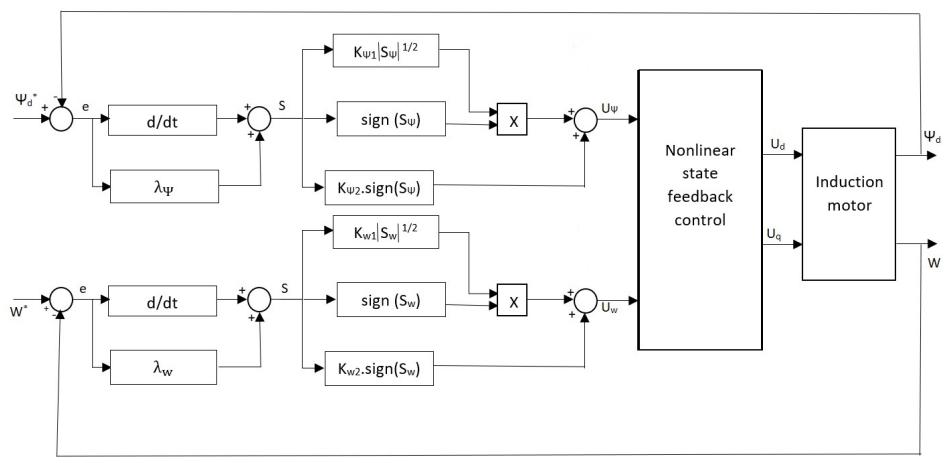
Figure 1. Induction Machine Control System
5. Simulation Results and discussion
To evaluate the performance of the induction motor control using Sliding Mode Control (SMC) and Super-Twisting Sliding Mode Control (ST-SMC), a detailed simulation was conducted under various operating conditions. The simulated motor is a six-pole (np = 3), 1/12 horsepower two-phase IM and the rated parameters of the motor were taken from [4] as
Rs= 1.7Ω, Rr =3.9Ω, Ls = Lr= 0.0014 H , M=0.0117 H , J =0.00011 K.gm2 , f= 0.00014N.m/rad/s f=0.00014N.m/rad/s.
Simulations were performed in which the motor accelerated from rest to a rated speed of 100 rad/s, followed by a step change to 140 rad/s at 0.4 s; second figure \ref{fig_omega}, a variable load torque was applied during the speed variation and parametric uncertainties were introduced by increasing the motor parameters by 100%.
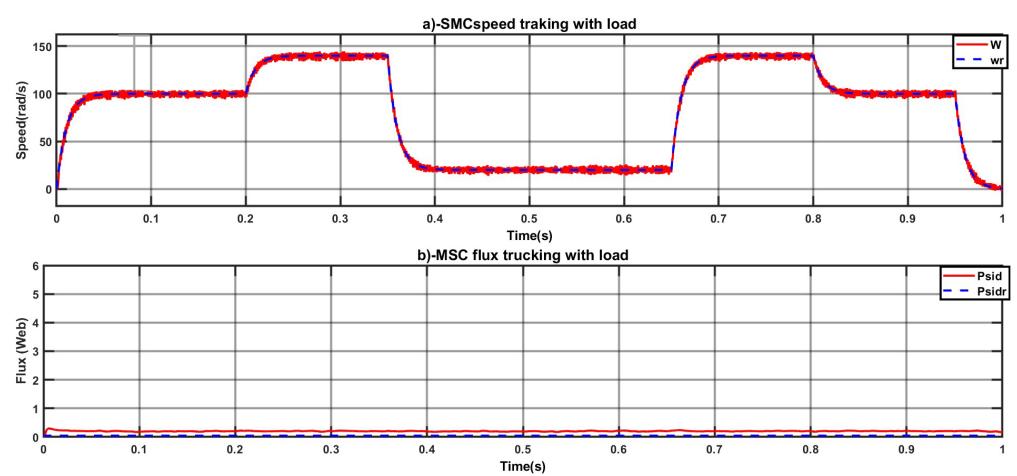
Figure 2. Speed and flux tracking performance of the conventional SMC under load variations and 100% parameter uncertainties.
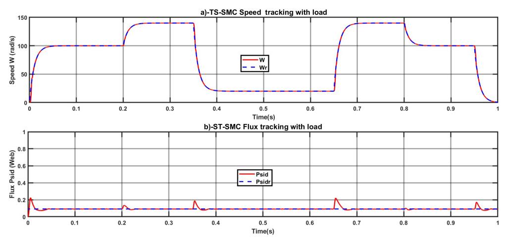
Figure 3. Speed and flux tracking response using the Super-Twisting SMC controller subject to load torque changes and 100% parameter variations.
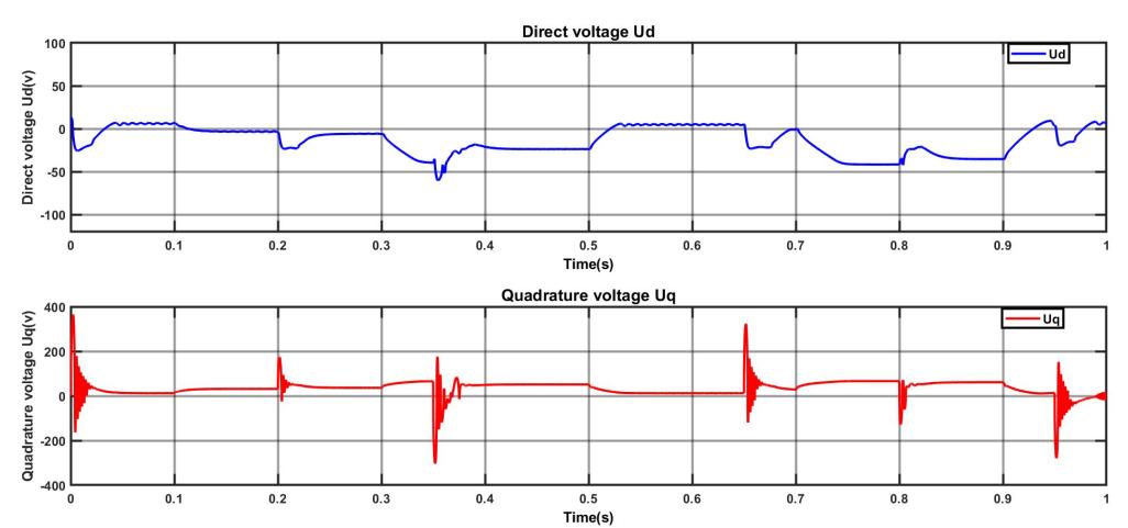
Figure 4. Direct and quadrature axis control voltages \((U_d,\,U_q)\) generated by the ST-SMC controller
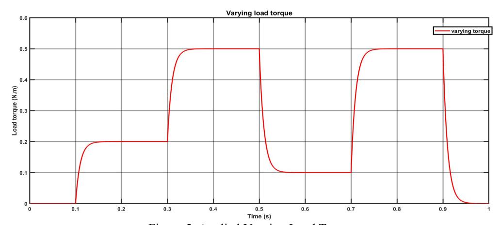
Figure 5. Applied Varying Load Torque
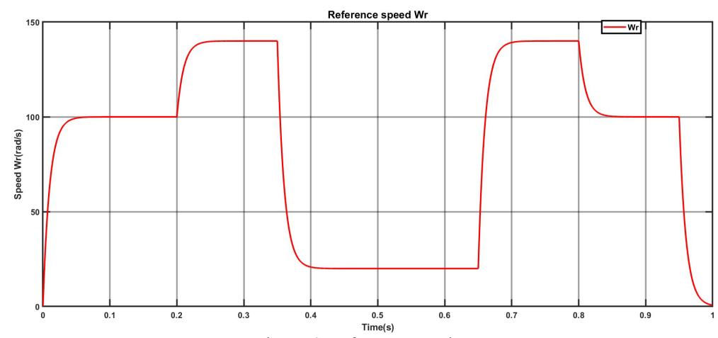
Figure 6. Reference speed Wr
The results presented in Figure 2(a) and figure 3(a) highlight the speed tracking performance for both the classical SMC and ST-SMC controllers. Figure 2(a) illustrates the behavior of the classical SMC, while Figure 3(a) shows the performance of the ST-SMC. Both controllers achieve effective speed tracking in response to the desired reference. However, there are significant differences in their dynamic responses. The classical SMC displays substantial chattering, especially during speed transitions and when the load torque is varied. This chattering, a common drawback of the classical SMC due to high-frequency switching, could lead to increased mechanical wear and higher losses in practical applications. In contrast, the ST-SMC achieves smooth speed tracking with considerably reduced chattering. The ST-SMC handles the transition from 100 rad/s to 140 rad/s effectively, even under load variations, with minimal overshoot and a quick settling time. This reduction in chattering improves the overall performance of the ST-SMC, making it more appropriate for applications demanding high precision and robustness.
Figure 2(b) and figure 3(b) depicts the flux tracking behavior for both controllers. The classical SMC Figure 2(b) provides adequate flux tracking; however, slight oscillations occur during load changes and speed variations, indicating some susceptibility to disturbances and parameter changes. In contrast, the ST-SMC figure 3(b)
delivers a much smoother flux response with minimal oscillations during transients and better alignment with the reference flux values. This improved disturbance rejection and robustness ensure the stability of the ST-SMC flux tracking, contributing to a more consistent operation of the induction motor.
To further highlight the contribution of the proposed method, a quantitative benchmark was conducted between PI-FOC, first-order SMC-FOC, and the proposed ST-SMC-FOC under identical scenarios (start-up, speed step 100 rad/s rightarrow 140 rad/s, stepped load torque, and 100% parameter variations). Table1 summarizes the key performance metrics.
While PI-FOC performs adequately under nominal conditions, it deteriorates under uncertainties and requires retuning. First-order SMC-FOC improves robustness but introduces strong chattering, which is visible in the flux/speed responses and the control voltages ud,uq.
In contrast, the proposed ST-SMC-FOC achieves fast convergence with negligible overshoot and smooth actuation signals, thereby suppressing chattering while retaining finitetime convergence. These results demonstrate that the proposed ST-SMC-FOC not only advances beyond PI-FOC and SMC-FOC, but also provides a computationally simpler alternative to recently reported adaptive or observer-augmented ST-SMC strategies (e.g., AQSTSMC [27]), while maintaining superior robustness and implementation feasibility.
| TC 11 1 | O 1'1 1' | • | C 4 11 | 1 1 1 1 1 | 1 1'4' |
|---|---|---|---|---|---|
| Table I | Ouantitative co | mnarison o | t controllers | under identical | l conditions |
| Controller | Overshoot (%) | Settling Time (s) | ITAE (Speed) | ||
| PI-FOC | ~12.0 | 0.36 | 0.75 | ||
| SMC-FOC (1st) | ~8.5 | 0.20 | 0.62 | ||
| ST-SMC-FOC | ~4.0 | 0.20 | 0.29 | ||
6. Conclusion
The simulation results highlight the performance, stability, and robustness of the classical SMC and ST-SMC control strategies under varying operating conditions, including load disturbances and parameter uncertainties. Although the classical SMC effectively tracks the reference values for speed and flux, it is hindered by chattering and shows reduced stability when faced with external disturbances and parameter variations. These drawbacks could affect the long-term reliability of classical SMCs, particularly in applications that require smooth operation and resilience to uncertainties.
In contrast, the ST-SMC demonstrates significant improvements in control performance, exhibiting smoother responses with minimal chattering and robust stability even under challenging conditions. Its ability to achieve faster convergence to reference values with better disturbance rejection makes ST-SMC a more reliable and precise choice for induction motor control applications. The enhanced stability, precision, and robustness of ST-SMC underscore its suitability for real-world scenarios, where maintaining optimal motor performance is essential despite the presence of dynamic disturbances and parameter variability.
Despite the promising simulation results, this study has certain limitations that pave the way for future research. The primary limitation is that the validation has been conducted purely in a simulation environment. The performance of the proposed controller should be verified on a real-time experimental test bench or a hardware-in-the-loop (HIL) platform to assess its practical efficacy and robustness against unmodeled hardware dynamics. Future work will therefore focus on the real-time implementation of the proposed ST-SMC strategy on DSP- or FPGA-based drive systems. Additionally, extending the controller to sensorless operation and evaluating its performance under more severe fault conditions, such as stator winding faults, represent important and challenging directions for further investigation.
7. References
- [1]. Chiasson, J, "Dynamic feedback linearization of the induction motor," International Journal of Control, 38, 1588–1594 (1993). https://doi.org/10.1109/9.241583.
- [2]. Ait Abbas, H., Belkheiri, M., Zegnini, B., "Feedback Linearization Control of an Induction Machine Augmented by Single Hidden Layer Neural Networks," International Journal of Control, 89(1), 140–155 (2016). <a href="https://doi.org/10.1080/00207179.2015.1063162">https://doi.org/10.1080/00207179.2015.1063162</a>.
- [3]. Hiware, R. S., Chaudhari, J. G., "Indirect Field Oriented Control for in duction Motor". In: Fourth International Conference on Emerging Trends in Engineering and Technology, Port Louis, Mauritius, pp. 191–194 (2011). https://doi.org/10.1109/ICETET.2011.56
- [4]. Chiasson, J. "Modeling and High Performance Control of Electric Machines." John Wiley and Sons, New Jersey (2005).
- [5]. Mishra, R. N., Mohanty, K. B. ,"Implementation of feedback-linearization modeled induction motor drive through an adaptive simplified neuro fuzzy approach". Sadhana, 42, 2113–2135 (2017). <a href="https://doi.org/10.1007/s12046-017-0741">https://doi.org/10.1007/s12046-017-0741</a>
- [6]. Sarkar, S. K., Das, S. K., "High performance nonlinear controller design for AC and DC machines: partial feedback linearization approach." International Journal of Dynamics and Control, 6, 679–693 (2018). https://doi.org/10.1007/s40435-017-0330-x.
- [7]. Slotine, J. E., Li, W., "Applied Nonlinear Control." Prentice-Hall, Englewood Cliffs, NJ (1991).
- [8]. Ameid, T., Talhaoui, H., Ammar, A., Azzoug, Y., Pusca, R., Romary, R., Lecointe, J.-P. "Hardware implementation of modified backstepping control for sensorless induction motor drive." In: IECON 2019-45th Annual Confer ence of the IEEE Industrial Electronics Society, vol. 1, pp. 1077–1082 (2019).
- [9]. Benheniche, A., Berrezzek, F. "Integral Backstepping Control of Induction Machine. "European Journal of Electrical Engineering, 23(4), 345–351 (2021). https://doi.org/10.18280/ejee.230408.
- [10]. Belkheiri, M., Boudjema, F. "Neural network augmented backstepping control for an induction machine." International Journal of Modelling, Identification and Control, 5(4), 288–296 (2008).
- [11]. Baker, R. C., Charlie, B. "Nonlinear unstable systems. International Journal of Control," 23(4), 123–145 (1989).
- [12]. Chen, F., Dunnigan, M. W. "Sliding-mode torque and flux control of an induction machine." IEE Proceedings Electric Power Applications, 150(2), 227–236 (2003).
- [13]. Balamurugan, S., Venkatesh, P., Varatharajan, M. "Fuzzy sliding mode control with lowpass filter to reduce chattering effect: an experimental validation on Quanser SRIP". Sadhana, 42, 1693–1703 (2017). https://doi.org/ 10.1007/s12046-017-0722-9.
- [14]. Yang, J., Li, S., Yu, X. "Sliding-mode control for systems with mismatched Uncertainties via a disturbance observer". IEEE Transactions on Industrial Electronics, 60(1), 160–169 (2013). https://doi.org/10.1109/TIE.2012. 2183841.
- [15]. Wang, Yuzhong, Zhao, Jun. "Neural-Network-Based Event-Triggered Sliding Mode Control for Networked Switched Linear Systems with the Unknown Nonlinear Disturbance". IEEE Transactions on Neural Networks and Learning Systems, 1–12 (2021). https://doi.org/10.1109/TNNLS.2021.3119665.
- [16]. Utkin, V. I., Guldner, J. "Sliding Mode Control in Electromechanical Systems". CRC Press (1999).
- [17]. Bartolini, G., Ferrara, A., Usai, E. "Chattering avoidance by second order sliding mode Control". IEEE Transactions on Automatic Control, 43(2), 241–246 (1998).
- [18]. Levant, A. "Higher order sliding modes, differentiation, and output feedback control". International Journal of Control, 76(9-10), 924–941 (2003).
- [19]. Xu, W., Zeng, P., Li, Y. "Adaptive sliding mode control for a high-speed induction Motor drive system with uncertainty". IEEE Transactions on In dustrial Electronics, 60(10), 4240–4250 (2013).
- [20]. Magallon, D. A., Castaneda, C. E., Jurado, F., Morfın, O. A. " Design of a Morlet wavelet control algorithm using super-twisting sliding modes applied to an induction machine". In: 2020 International Joint Conference on Neural Networks (IJCNN), pp. 1– 8 (2020). https://api.semanticscholar.org/ CorpusID:221652985
- [21]. Ali, M. M., Xu, W., Junejo, A. K., Elmorshedy, M. F., Tang, Y. " One New Super-Twisting Sliding Mode Direct Thrust Control for Linear Induction Machine Based on Linear Metro". IEEE Transactions on Power Electronics, 37, 795–805 (2021).
- [22]. Morawiec, M., Lewicki, A. "Speed Observer Structure of Induction Machine Based on Sliding Super-Twisting and Backstepping Techniques". IEEE Trans actions on Industrial Informatics, 17, 1122–1131 (2021).
- [23]. Rivera, Jorge and Garcia, Luis and Mora, Christian and Raygoza, Juan J and Ortega, Susana. "Super-twisting sliding mode in motion control systems", Sliding Mode Control, vol. 1, pp. 237–254, (2011), InTech Rijeka, Croatia.
- [24]. Krim, Saber and Gdaim, Soufien and Mimouni, Mohamed Faouzi. "Robust Direct Torque Control with Super-Twisting Sliding Mode Control for an Induction Motor Drive", Complexity, vol. 2019, no. 1, pp. 7274353, (2019), Wiley Online Library.
- [25]. Krim, S., Mimouni, M. F. "Design of improved direct torque control based on a fivelevel torque controller and a new Sugeno Takagi fuzzy supertwisting controller applied to an induction machine". Engineering Applications of Artificial Intelligence, 126, 106900 (2023).
- [26]. Wang, B., Wang, T., Yu, Y., Luo, C., Xu, D. "Convergence trajectory optimization of supertwisting sliding mode current control for induction motor drives". IEEE Transactions on Industrial Electronics, 69(12), 12292–12304 (2021). https://doi.org/10.1109/TIE.2021.3130328.
- [27]. Siddiki, A.B.M.I., Sagor, I.H., Amin, I.K., Uddin, M.N. "Adaptive Super Twisted Sliding Mode Control of Induction Motor for Enhanced Performance". Proc. IEEE Industry Applications Society Annual Meeting (IAS), pp. 1–6 (2025). https://doi.org/10.1109/IAS62731.2025.11061623
- [28]. Ba-Razzouk, Abdellfattah and Cheriti, Ahmed and Olivier, Guy and Sicard, Pierre. "Field-oriented control of induction motors using neural-network de couplers", IEEE Transactions on Power Electronics, 12, 4, pp.752–763, (1997).
- [29]. Ba-Razzouk, A and Cheriti, A and Olivier, Guy. "A neural networks based field oriented control scheme for induction motors". IAS'97. Conference Record of the 1997 IEEE Industry Applications Conference Thirty-Second IAS Annual Meeting, 2, pp.804–811, (1997),
- [30]. Saravanakumar, R and Kumar, K Vinoth and Ray, KK. "Sliding mode control of induction motor using simulation approach". International Journal of Computer Science and Network Security, 9, 10, pp93–104, (2009).
- [31]. Panchade, VM and Chile, RH and Patre, BM. "A survey on sliding mode control strategies for induction motors", Annual Reviews in Control Elsevier, 37, 2, pp289–307, (2013),
- [32]. Yan, L., Wang, F., Dou, M., Zhang, Z., Kennel, R., Rodriguez, J. "Active Disturbance Rejection Based Speed Control in Model Predictive Control for Induction Machines". IEEE Transactions on Industrial Electronics, 67(4), 103593 (2020).
- [33]. Razzouk, A., Cheriti, A., Olivier, J., Sicard, P. "Field oriented control for induction motors using neural networks decouplers". In: Proceedings of the IDS Conference, Canada (1995).
- [34]. Gao, Z. "Scaling and parameterization based controller tuning". In: Proceedings of the American Control Conference, New York, USA, pp. 4989–4996 (2003).
- [35]. Bashir, A., Khan, S., Iqbal, N., Bashmal, S., Ullah, S., Usman, M. "A Re view of the Various Control Algorithms for Trajectory Control of Unmanned Underwater Vehicles". Sustainability (2023).
- [36]. Liu, W., Ye, H., Yang, X. "Super-Twisting Sliding Mode Control for the Trajectory Tracking of Underactuated USVs with Disturbances". Journal of Marine Science and Engineering, 11, 636 (2023).
- [37]. Benderradji, H., Benamor, A., Chrifi-Alaoui, L., Bussy, P., Makouf, A. "Second Order Sliding Mode Induction Motor Control with a New Lyapunov Approach". International Multi-Conference on Systems, Signals & Devices, 1–6 (2012). r).
- [38]. Van, T. L., Nguyen, T. H., Choi, H. H. "Super-Twisting Sliding Mode Control for Speed Ripple Minimization of Permanent Magnet Synchronous Motor". IEEE Transactions on Industrial Informatics, 19(8), 9123-9132 (2023). <a href="https://doi.org/10.1109/TII.2023.3243290">https://doi.org/10.1109/TII.2023.3243290</a>.
- [39]. Xia, C., Liu, T., Shi, J., Song, Z. "Continuous Super Twisting Sliding Mode Control For Current Loop of Permanent Magnet Synchronous Motor Drives". IEEE Transactions on Industrial Electronics, 69(9), 8524-8534 (2022). https://doi.org/10.1109/TIE.2021.3073303.
- [40]. Wang, Y., Zhang, G., Wang, X., Wang, Y. "Sensorless Control of PMSM Based on Super Twisting Sliding Mode Observe". IEEE Transactions on Power Electronics, 36(4), 4627-4636 (2021). https://doi.org/10.1109/TPEL.2021.3087427.
(AVICS).
Saad Kelam was born in Algeria in 1979. He is a researcher and Ph.D. candidate in the Department of Automation at the University of Science and Technology of Oran Mohamed-Boudiaf (USTOMB) Algeria. He received his Engineer degree in automatic Control from the University of Science and Technology of Oran, Algeria, in 2005, followed by a Master's degree in Automatic Control from the University of Laghouat in 2012. He is currently pursuing his Ph.D. in Automation at USTOMB, affiliated with the Laboratory of Automation, Vision, and Intelligent Control of Systems
Rachida Hadiby Ghoul is a Professor of Automatic Control at the University of Science and Technology Oran — Mohamed Boudiaf (USTO), Algeria. She holds a Doctorate d'État in Automatics-Productics from the University of Annaba. With extensive expertise in discrete event systems, production systems, and industrial informatics, her research focuses on modeling and control using Petri nets and hybrid control methods. Professor Ghoul has held several significant leadership positions at USTO, including Vice-Rector for Postgraduate Studies and Scientific Research (2019-2020)
and Chair of the Scientific Committee of the Automation Department since 2014.
Mohammed Belkhiri was born in Algeria in 1977. He received the Engineer degree in Electrical Engineering and Electronics from the Institute of Electrical and Electronic Engineering, University of Boumerdès, Algeria, in 2000. He then earned the Magister degree in Robotics and Automatic Control in 2002 and the Ph.D. degree in Automatic Control in 2008, both from the École Nationale Polytechnique, Algiers, Algeria. From 2003 to 2008, he served as an Assistant Professor at the University of Laghouat, Algeria. He was promoted to Associate Professor in 2008, a position he
held until 2016. Since 2011, he has been affiliated with the Telecommunications, Signals, and Systems Research Laboratory at the University Amar Telidji, Laghouat, Algeria. Since 2016, he has been a Full Professor with the Electrical Engineering Department at the University of Laghouat. His research focuses on nonlinear, adaptive, and intelligent neural network control of electromechanical systems, with applications in power conversion, robotics, and autonomous systems.