
Introduction
Indonesia is a country that is exposed to earthquake hazards and therefore it is necessary to conduct further analysis of the response of building and non-building structures due to earthquake loading. Indonesia is also known for its large population, especially the city of Jakarta. Therefore, the use of land above ground level is very dense. On-grade traffic congestion and challenges in many big cities in Indonesia demand that underground mass rapid transit (MRT) is developed as a solution. The MRT Jakarta underground structure is currently a critical infrastructure if an earthquake occurs.
The principles of designing and analyzing underground structures differ from those of above-ground structures. Underground structures are designed by considering behavior of the soil surrounding them [1]. The performance of an underground station structure subjected to an earthquake can be evaluated by looking at the structure's deformation, forces, and bending moment responses. Several methods, from conventional to complex computation, are available, utilizing Racking free-field deformation and dynamic analysis methods to obtain these responses. While dynamic computation is a suitable computational method that integrates multiple factors, such as dynamic soil parameters, structural stiffness, and earthquake motion, it frequently demands a significant amount of time and a proficient grasp of soil mechanics principles.
In many cases, simplified methods, such as free-field deformation and pseudo-static approaches, do not consider soil-structure interaction and ground motion mechanism effects on the underground structure's seismic behavior [1,2]. The structure is expected to resist the design earthquake, so a better analysis is needed to result in a more accurate response of the MRT underground structure to seismic waves.
Typical MRT stations use a rectangular underground structure. The response of an underground structure to earthquake loads can be seen through the deformation of the racking that occurs among other responses.
Deformation in underground station structures can be determined using various methods, i.e., dynamic time history analysis methods, pseudo-statics, and racking free-field deformation methods.
Several studies have been conducted to determine the effect of various parameters on the response of underground structures to earthquake loads. For instance, Haiyang et al. [3] conducted research by performing centrifugal tests on an underground structure model. Their study found that an increase in PGA value leads to an increase in the maximum strain response and relative deformation in the structure. Wang et al. [4] conducted research on irregular cross-sections without D-walls using FEM calculations; it was seen that the response of each cross-section of the structure varies with the earthquake load. The difference in response is more significant for smaller earthquake loads and becomes more pronounced as the earthquake load increases. The response of underground structures is affected not only by earthquake intensity and soil type but also by the presence or absence of D-walls. Based on Hashash [2], an embedded D-wall will increase the racking deformation of the structure because the D-wall absorbs earthquake energy and transmits it to the structure. According to Zhuang et al. [5], their research on irregular cross sections with and without D-walls revealed that including embedded D-walls can decrease harm to underground structures. Their study used a two-level rectangular underground structure model including D-walls.
The present study aimed to investigate the impact of site class, peak base acceleration, and earthquake mechanism type on rectangular underground structure deformation using the FDM software.
Methodology
Numerical Modeling
Research conducted by Ridwan et al. [6] obtained cross-sections from the depth of the soil showing the location of the bedrock (Figure 1) with a value of shear wave velocity (Vs) > 760 m/s in Jakarta, as shown in Figure 2. The bedrock depth was found to be 350 m to 725 m. Based on Ridwan et al [6], the soil in the city of Jakarta as the review location is dominated by medium soil and soft soil. Based on research that has been conducted previously, here, the parametric study will use a base rock depth of 350 meters. In addition to describing the conditions in Jakarta, a bedrock depth of 350 meters was chosen for the efficiency of the computation time in the software used. The parameters that were varied in the parametric study were: site class (Soil SD and Soil SE), earthquake mechanism (megathrust and shallow crustal), and PBA (0.1 g, 0.3 g, and 0.5 g).
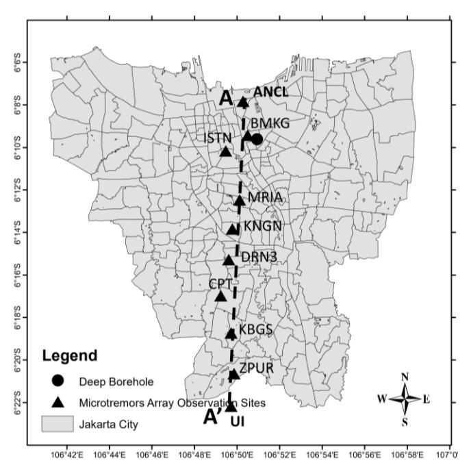
Layout of microtremor array observation sites in Jakarta City [6]
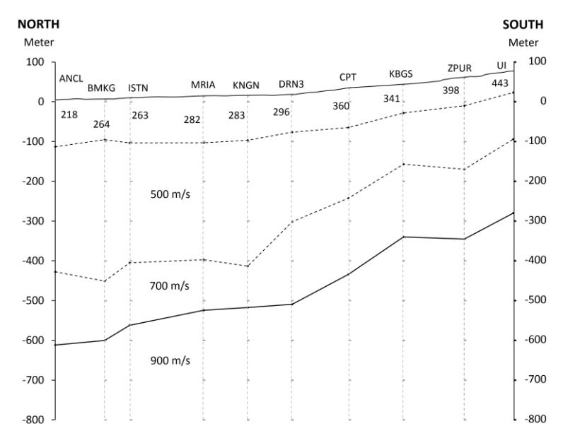
Figure 2 Cross-section depth of soil from north to south direction micrometer array results [6].
At a depth of 30 meters below the ground surface, the site class varies. This was modeled as homogeneous clay with different soil properties according to the SD and SE site classes in SNI 1726:2019. The Vs value was calculated based on the correlation by Ohta and Goto [7] in Eq. (1) and the correlation by Seed and Idriss [8] in Eq. (2). These two correlations are commonly used and were selected because they cover all soil types. Based on research by Delfebriyadi et al. [9], one of the correlations that are most suitable for the Jakarta location are that of Ohta and Goto. The value of Vs is the average of the results of the two correlations. The shear strength value in clay was calculated using a correlation based on the NSPT value according to Terzaghi (1979) as in the Eq. (3).
\[V_s(m/s) = 85.35 \times NSPT^{0.348} \tag{1}\]
\[V_{\rm s}(m/{\rm s}) = 61.4 \times NSPT^{0.5} \tag{2}\]
\[c_{y} = 6 \times NSPT(kPa) \tag{3}\]
Calculation of shear modulus (G) and bulk modulus (K) values was done using Eqs. (4) and (5):
\[G_{max} = \rho V_s^2 \tag{4}\]
\[K = \frac{2G(1+v)}{3(1-2v)} \tag{5}\]
Similar soil profiles were used for depths ranging from 30 to 350 meters below ground level. The soil parameters used, as shown in Table 1, are plotted in Figure 3.
Table 1 Soil data input.
| Layer Name | Thickness (m) | NSPT | Total unit weight (kN/m³) | Vs (m/s) | Gmax (MPa) | ν | K (kPa) | Su (kPa) |
|---|---|---|---|---|---|---|---|---|
| Site Class SD | 30 | 16 | 18 | 235 | 99.23 | 0.4 | 463090 | 96 |
| Site Class SE | 30 | 5 | 17 | 143 | 34.94 | 0.4 | 163055 | 30 |
| Clay 1 | 30 | 92 | 18 | 500 | 458.72 | 0.4 | 2140673 | 551 |
| Clay 2 | 50 | 114 | 19 | 550 | 585.88 | 0.4 | 2734116 | 685 |
| Clay 3 | 80 | 167 | 20 | 650 | 861.37 | 0.4 | 4019713 | 1002 |
| Clay 4 | 160 | 198 | 20 | 700 | 998.98 | 0.4 | 4661914 | 1185 |
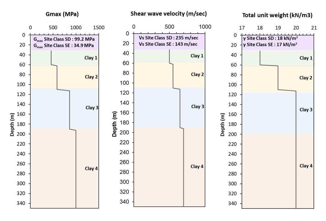
Soil profile at a depth of 30 to 350 meters.
Figure 4Figure 4 shows a typical modeled underground station structure, with a depth of 5 meters below ground level. The structural parameters used in the parametric study are shown in Table 2.
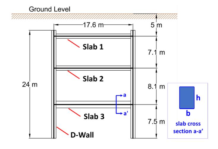
Simple illustration of structures for parametric studies.
Table 2 Structural parameters used in the parametric study.
| Beam | b (m) | h (m) | fc' (Mpa) | Area (m²) | Mom/Inertia (m4 ) | E (Pa) |
|---|---|---|---|---|---|---|
| Slab 1 | 1 | 1 | 40 | 1 | 0.083 | 2.97 × 10¹⁰ |
| Slab 2 | 1 | 1 | 40 | 1 | 0.083 | 2.97 × 10¹⁰ |
| Slab 3 | 1 | 1.5 | 40 | 1.5 | 0.281 | 2.97 × 10¹⁰ |
| Dwall | 1 | 1 | 40 | 1 | 0.083 | 2.97 × 10¹⁰ |
The input motion used was modified time history. The earthquake used in the analysis for the megathrust earthquake mechanism was Chile UHS, while for the shallow crustal earthquake mechanism, Shallow Crustal Whittier Narrow was used. Then, the earthquake was modified with the help of EZ-Frisk to become PBA = 0.1 g, PBA = 0.3 g, and PBA = 0.5 g with a return period of 2500 years, as shown in Figure 5.
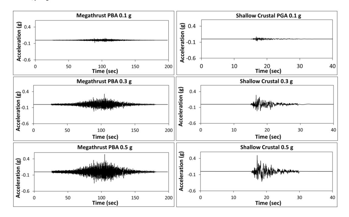
Input motions used in parametric studies.
1D Wave Propagation
Site response analysis is crucial in earthquake engineering, as it typically initiates structural response calculations for soil-structure interaction issues [10]. Prior to conducting dynamic analysis in the FLAC software, it is essential to calibrate the results of 1D propagation in FLAC with 1D Wave Propagation software. In this study, we utilized the DEEPSOIL software for calibration.
The analysis by Hutabarat [11] found that the GQ/H model provides good predictions of cyclic behavior under high strain levels. The analysis carried out by Basarah [12] found that the non-Masing hysteretic model is better for knowing surface spectra in the intermediate period. Therefore, this study used the GQ/H model with non-Masing re/unloading for 1D wave propagation in the DEEPSOIL program.
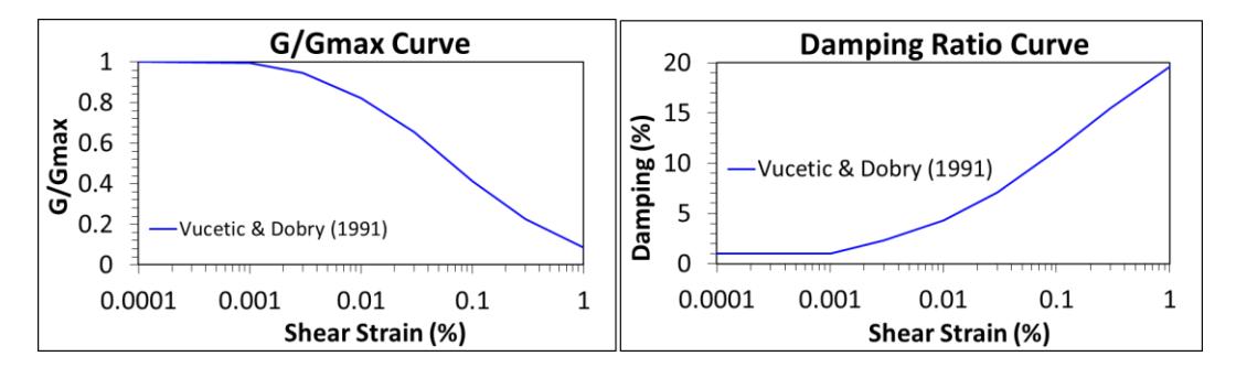
G/Gmax and damping ratio to strain curve by Vucetic and Dobry (1991).
In calibrating between DEEPSOIL and FLAC, it is necessary to calibrate the degradation curve in FLAC with the target degradation curve. The target degradation curve used in this study for clay soils was the reference curve from Vucetic and Dobry [13] because the curve parameter needed is only the plasticity index value. Using hysteretic damping in FLAC with the sigmoidal sig3 model, it is necessary to determine the coefficients a, b, and x0. The equations used to determine a, b, and x0 based on the FLAC Manual are as follows:
\[M_{S} = \frac{a}{1 + exp(-(L - x_{0})/b)} \tag{6}\]
In Eq. (6), Ms is G/Gmax and L is Log (shear strain). The coefficients a, b, and x0 of the hysteretic damping used are shown in Table 3.
| Hysteretic Damping Coefficient | |||||||
|---|---|---|---|---|---|---|---|
| Soil Layers | a b | Xo | |||||
| Site Class SD (@0-30 meters) | 1.008 | -0.498 | -1.220 | ||||
| Site Class SE (@0-30 meters) | 1.007 | -0.486 | -1.228 | ||||
| Clay 1 (@30-60 meters) | 1.007 | -0.492 | -1.223 | ||||
| Clay 2 (@60-110 meters) | 1.001 | -0.493 | -1.197 | ||||
| Clay 3 (@110-190 meters) | 0.997 | -0.463 | -1.220 | ||||
| Clay 4 (@190-350 meters) | 0.996 | -0.451 | -1.232 | ||||
Table 3 Sig3 hysteretic damping coefficient.
By using the help of MODRED.FIS in FLAC, the G/Gmax curve, and the damping ratio to strain curve were obtained for each soil depth reviewed, as shown in Figure 7.
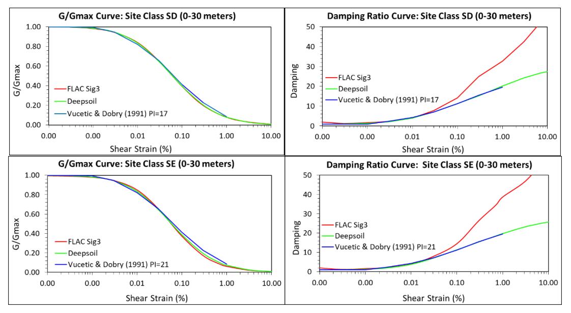
G/Gmax and damping ratio to strain curve at a depth of 30 meters.
In addition to using hysteretic damping, Rayleigh damping was used in the analysis to avoid low-level oscillations. The Rayleigh coefficient was determined at 0.2% by including the center frequency value for each earthquake load.
A comparison of the acceleration on the ground surface and the spectral response of the wave propagation results using DEEPSOIL and FLAC was made, as shown in Figure 8. The results of wave propagation using FLAC and DEEPSOIL are already quite similar.
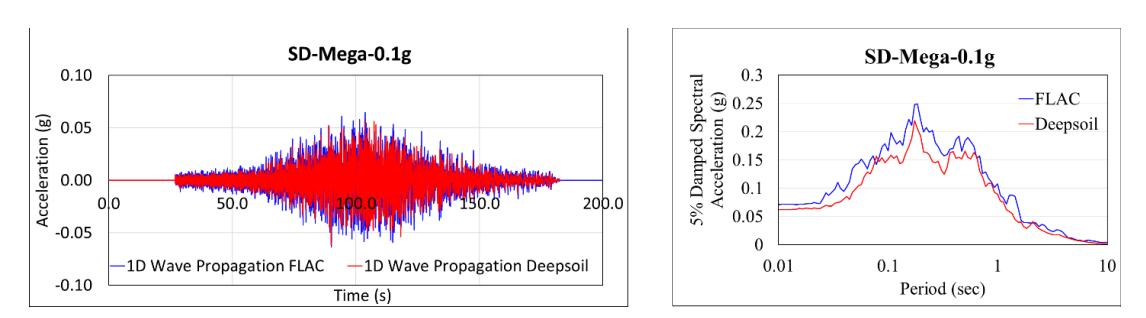
The results of ground surface acceleration and spectral response at 30 meters below the ground surface for SD soil and a Shallow Crustal earthquake load of 0.1 g.
The damping curve calibration is tricky at high strain, but a better calibration can be produced with a perfectly matching G/Gmax curve calibration. A perfectly matching damping or G/Gmax curve will produce a calibration that is better still. Rayleigh damping will also affect the calibration results. Research done with constant Rayleigh
damping intensity values can vary the magnitude of the stiffness, mass, and center frequency coefficient to produce a better calibration.
In this study, changing the mass coefficient and center frequency values had a more significant effect than changing the stiffness coefficient. The greater the value of the mass coefficient and center frequency coefficient, the more the spectral curve will decrease or the magnitude of the acceleration will decrease. The modified stiffness coefficient value gives uncertain changes to the spectral curve. However, based on the spectral curve generated by changing the stiffness coefficient, in general, the greater the stiffness value, the more the spectral curve will increase. The final calibrated curves are shown in Figure 7. The modulus reduction curve shows that sig3 hysteretic damping in FLAC is close to the target curve. However, the damping curve shows a significantly higher value at high strain compared to the target curve, although it is quite close at small to medium strain (0.001% to 0.3%). The difference seems to be more significant for high-intensity motion with large shear strain, as shown in Figure 8.
Dynamic Analysis Using FLAC 2D
The constitutive soil model was developed to make the soil's inelastic cyclic behavior quite complex so that more parameters are needed. However, alternatively, we can use a constitutive model with reasonably simple input, namely Mohr-Coulomb, with the addition of damping to represent the inelastic hysteretic behavior. In this study, the constitutive model of the Mohr-Coulomb soil was used with the addition of hysteretic and Rayleigh damping. Rayleigh damping was used to avoid low-level oscillations. It was assumed to be a Compliant Base in FLAC in dynamic analysis modeling. Quiet boundaries were used with input stress or force; therefore, it was necessary to convert the velocity data first.
In dynamic analysis, boundary conditions result in unnecessary reflections. Therefore, a deep enough modeling is needed for bedrock, but the deeper the modeling, the longer the calculation time will be. Therefore, the boundary conditions used at the base of the model were quiet boundaries. The right and left sides of the model were free-field boundaries, which model areas without any structure and follow an infinite distance model. In dynamic modeling, it is suggested that the distance between the boundaries of the horizontal span of the structure is at least three times greater than the width of the underground structure, because the influence of the boundary on the structure being analyzed is relatively small and still acceptable [14]. Based on Hashash [2], the boundary distance was also three times larger than the width of the structure, i.e., 4.5 times the width of the structure; therefore, in the dynamic analysis in this study, the boundary distance between the left and right sides of the structure was 4.5x the width of the structure.
In this analysis, the modeling was performed by cutting the bedrock to a depth of 60 meters below the ground surface. It is important to keep the model simple to reduce computation time. Bedrock cutting is carried out in the soil with a substantially linear response [15]. Thus, the input based on the FLAC model used velocity data resulting from wave propagation using DEEPSOIL at 60 meters below the ground surface. Before using the data resulting from wave propagation using DEEPSOIL, it was necessary to do a baseline correction. The 2D numerical model in FLAC is shown in Figure 9.
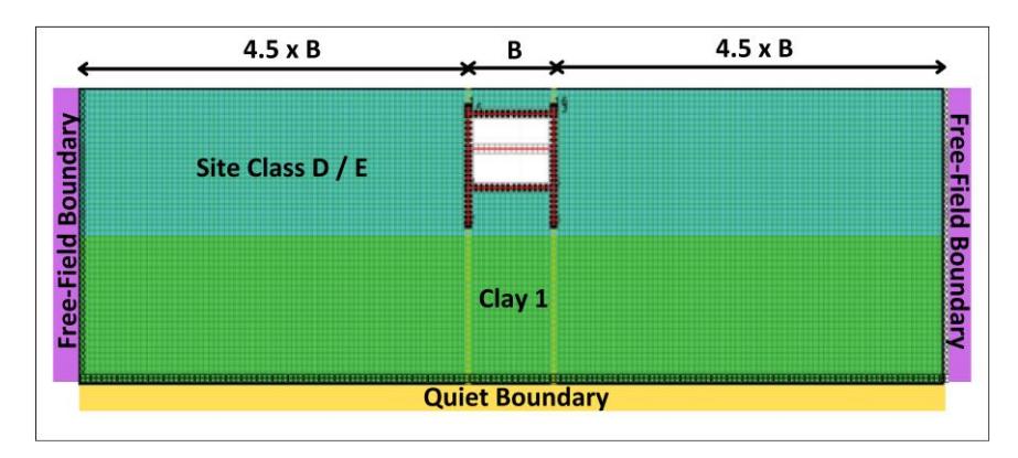
Dynamic analysis modeling in FLAC software.
Result and Discussion
Relative deformation data processing was carried out in several ways. The first method (Method 1) was carried out according to the analysis carried out by Hashash [2] by finding the most significant absolute difference in deformation at the same time, or with the following equation:
\[\Delta_{box} = max[abs(\delta_{h,Top} - \delta_{h,Bottom})] \tag{7}\]
Then, at the same time, deformation plotting was carried out at the point between the base slab and the top slab of the structure so that the deformation was obtained, as shown in Figure 10.
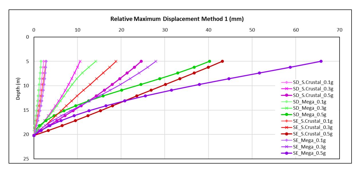
Racking deformation value from the calculation of the biggest difference between the base slab and the top slab at the same time (Method 1).
The second method (Method 2) plotted the relative deformation data by looking for the most significant deformation difference between the nodes on the base slab and the top slab, even though they do not coincide. This method was carried out because it considers that there are relatively large differences in deformation within a very short time. One study on the SE class site represents it with a shallow crustal PBA 0.1 g earthquake, as shown in Figure 11. Plotting results as shown in Figure 12 were obtained.
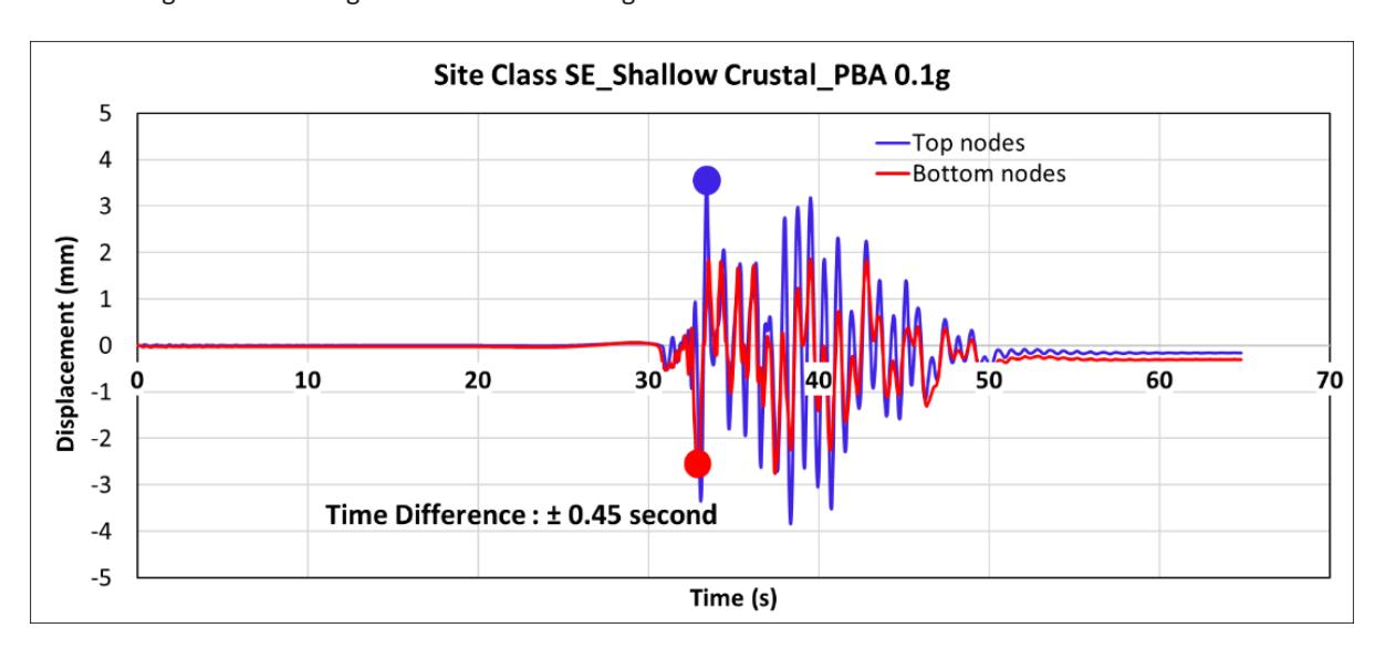
Displacement time history of top and bottom nodes of structure on site class SE subjected to the shallow crustal mechanism with a PBA of 0.1 g.
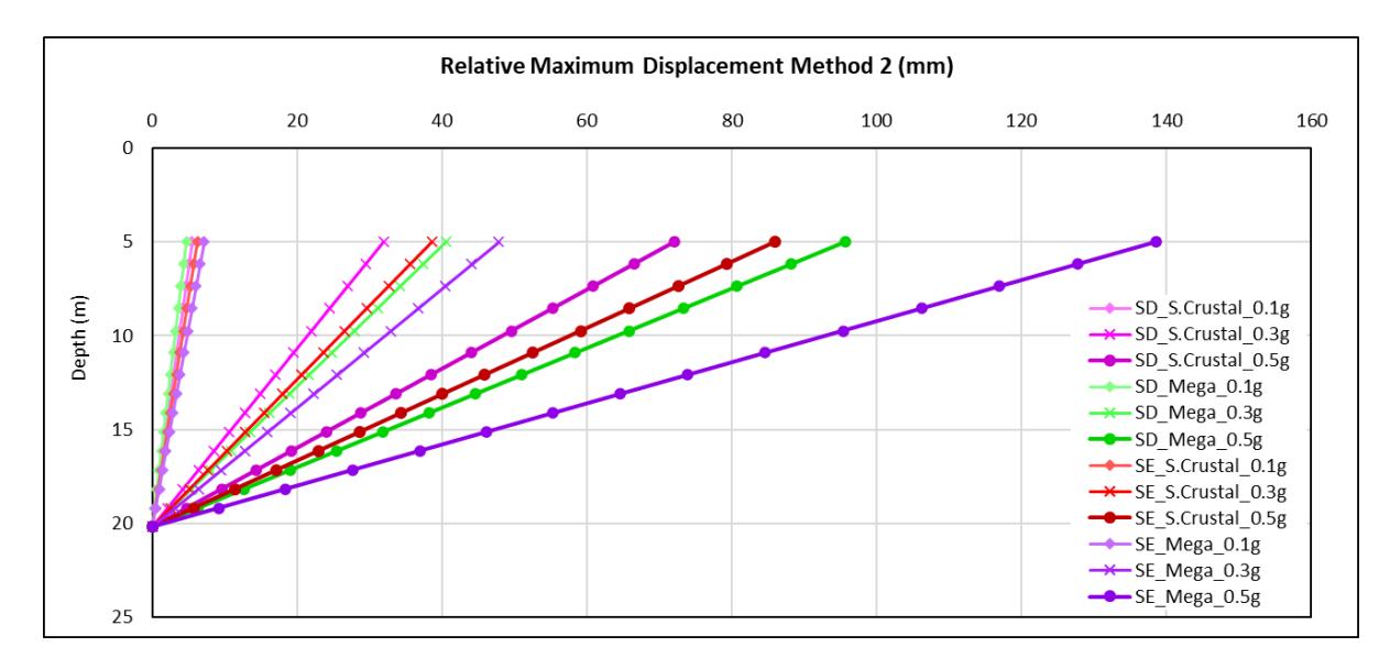
Racking deformation value from the calculation of the largest difference between the base slab and the top slab (Method 2).
The third method (Method 3) plotted the relative deformation based on the maximum strain value. The generated strain time history at each node of the structural wall was obtained from each node as a result of dynamic analysis, followed by the maximum strain. From the maximum strain value obtained, the displacement value was calculated by multiplying the strain by the partition of each node (in units of length) so that the relative deformation plotting for each study was obtained, as shown in Figure 13.
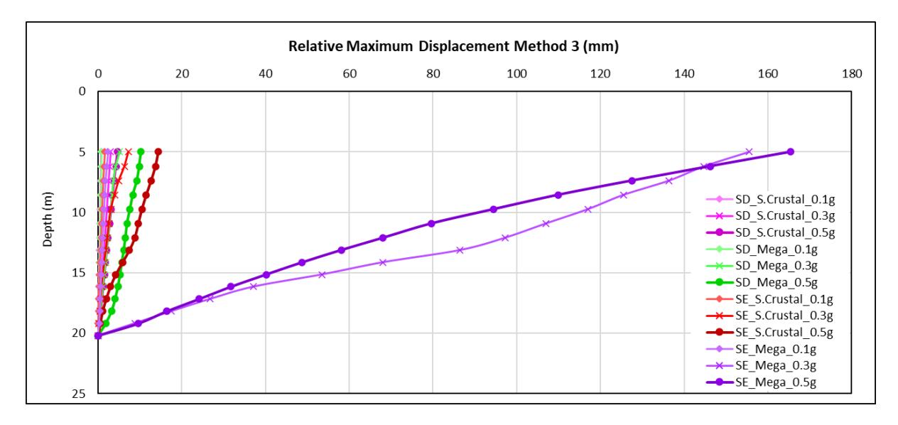
Racking deformation value from calculation of maximum shear strain value at each node (Method 3).
Effect of Site Class
In Figures 10, 12, and 13, it can be observed that the stiffness of the soil surrounding the underground station structure was inversely proportional to the deformation. This implies that the softer the soil, the greater the deformation. For instance, with Method 1, the racking deformation in site class E for a shallow crustal earthquake with a PBA of 0.5 g was about 43.7 mm or 1.8 times compared to that for site class D. Similarly, for a megathrust earthquake with a PBA of 0.5 g, the racking deformation of site class E was 65.3 mm or 1.6 times compared to that for site class D. These results are consistent with the behavior observed in Wang's study [1], where two cases were compared, with the soil parameter of Case 2 being stiffer than that of Case 1. The results of the racking deformation of Case 2 were smaller than that of Case 1, indicating that the stiffer the soil, the smaller the racking deformation. The results of the analysis of the effect of soil class are also consistent with the research conducted by Hashash [2], who found that the racking deformation in soft soil (flexibility ratio < 1) is relatively large. However, the racking deformation is smaller in denser soil (flexibility ratio > 1).
Effect of Ground-Motion Intensity
The wall deformation values were highest during the 0.5 g PBA earthquake, as shown in Figures 10, 12, and 13. Conversely, the smallest wall deformation value was observed during the 0.1 g PBA earthquake. This indicates that wall deformation increases with the magnitude of the earthquake load. For instance, with Method 1, the racking deformation in site class D for a megathrust earthquake with a PBA of 0.5 g was about 40.1 mm or 2.8 times compared to that for megathrust PBA 0.3 g motion. Similarly, in site class D for shallow crustal PBA 0.5 g motion was about 24.8 mm or 2.3 times compared to that for shallow crustal PBA 0.3 g motion. This result is in line with the results obtained by Haiyang [3] and Wang [4] i.e., an increase in the PGA value leads to an increase in the maximum strain response and relative deformation of the structure.
Effect of Earthquake Mechanism
Based on Figure 10, it was obtained that the relative deformation along the structural wall between the upper and lower slabs for the megathrust earthquake mechanism was greater than for the shallow crustal earthquake mechanism. Figure 12 shows that the relative deformation of the wall for the megathrust mechanism was greater than that for the shallow crustal earthquake mechanism. It also can be seen in Figure 13 that the relative deformation along the structural wall with the megathrust earthquake mechanism was greater than that with the shallow crustal earthquake mechanism.
It was found that with the same earthquake intensity but with a significant difference in duration between the earthquake mechanisms, the response of the underground station structure is different. It is known that the intensity of megathrust and shallow crustal earthquakes is the same. However, with a longer duration of a megathrust earthquake compared to a shallow crustal earthquake, more deformation is produced by a larger megathrust earthquake than by a shallow crustal earthquake. Large earthquake energy will also further increase the racking deformation of the underground station structure.
Relative Maximum Displacement
The deformation recapitulation in Table 4 compares the three results with the Method 1. Conservative results were produced using Method 2, which shows that the scale with Method 1 is quite large in all parametric studies and, in some cases, based on Method 3. Therefore, for underground station structure designs, it is necessary to consider racking deformation using all three methods.
| Racking Deformation (mm) | Method X/ Method 1 | ||||||
|---|---|---|---|---|---|---|---|
| Parametric Study | Method 1 | Method 2 | Method 3 | Method 1 | Method 2 | Method 3 | |
| SD_S.Crustal_0.1g | 2.1 | 5.5 | 0.8 | 1.0 | 2.6 | 0.4 | |
| SD_S.Crustal_0.3g | 10.8 | 31.9 | 3.0 | 1.0 | 3.0 | 0.3 | |
| SD_S.Crustal_0.5g | 24.8 | 72.1 | 4.9 | 1.0 | 2.9 | 0.2 | |
| SD_Mega_0.1g | 1.8 | 4.7 | 0.8 | 1.0 | 2.6 | 0.5 | |
| SD_Mega_0.3g | 14.4 | 40.6 | 8.9 | 1.0 | 2.8 | 0.6 | |
| SD_Mega_0.5g | 40.1 | 95.6 | 9.3 | 1.0 | 2.4 | 0.2 | |
| SE_S.Crustal_0.1g | 3.3 | 6.3 | 1.6 | 1.0 | 1.9 | 0.5 | |
| SE_S.Crustal_0.3g | 19.4 | 38.6 | 7.6 | 1.0 | 2.0 | 0.4 | |
| SE_S.Crustal_0.5g | 43.7 | 86.0 | 14.5 | 1.0 | 2.0 | 0.3 | |
| SE_Mega_0.1g | 3.4 | 7.2 | 2.2 | 1.0 | 2.1 | 0.7 | |
| SE_Mega_0.3g | 27.4 | 47.8 | 160.2 | 1.0 | 1.7 | 5.9 | |
| SE_Mega_0.5g | 65.3 | 138.5 | 171.4 | 1.0 | 2.1 | 2.6 | |
Table 4 Deformation recapitulation table.
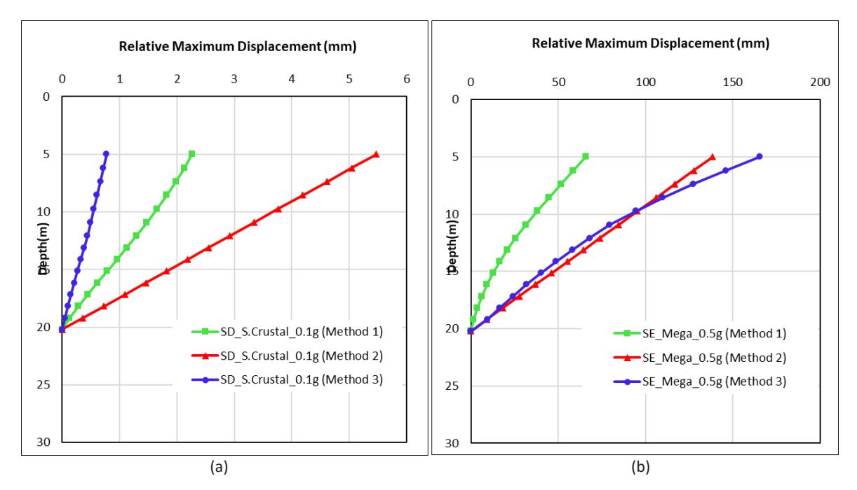
Deformation plots with the three methods: (a) on a SD class site with a shallow crustal PBA 0.1 g earthquake; (b) on a SE class site with a megathrust PBA 0.5 g earthquake.
In graphical form, plotting was carried out on two parametric studies: Figure 14 (a) for a parametric study on an SD class site subjected to a shallow crustal PBA 0.1 g earthquake and Figure 14(b) for a parametric study on a SE class site subjected to a megathrust PBA 0.5 g earthquake. It can be seen in Figure 14(a) that the most significant displacement was produced by Method 2, while Figure 14 (b) shows that the most significant displacement was produced by Method 3. In this parametric study, dynamic analysis was carried out while still modeling embedded D-walls and without columns. The deformation range obtained in this study from the smallest to the largest from all racking deformation calculation methods was 0.08 cm to 17.14 cm.
Conclusions
The parametric study involving dynamic time-history analysis that was conducted in this study provided some findings that were not identified with conventional pseudo-static analysis. The following are the conclusions of this study: site class parameters, ground-motion intensity, and earthquake mechanisms influence the relative deformation of the walls of the underground station structure. Increasing the soil stiffness around the structure will make the resulting relative deformation smaller and vice versa. Increasing the intensity of the PBA value tends to provide more significant relative deformation. This study demonstrated that the megathrust earthquake mechanism resulted in more substantial deformation compared to the shallow crustal earthquake mechanism with the same PBA value. This is due to the longer duration of megathrust earthquakes, which results in significantly more energy being released. In locations with a high probability of megathrust earthquakes, it is necessary to consider the potential for increased racking deformation of underground station structures due to considerable earthquake energy during the design process. In this study, the deformation range produced in the underground station structure was 0.08 cm to 17.14 cm. It should be noted that the deformation results were obtained for structures without columns and with embedded D-wall modeling.
Acknowledgement
We would like to thank PT WSP Engineering and PT ARUP INDONESIA for providing the seed motion data of the Site-Specific Response Analysis (SSRA) MRT project phase II that was processed in the analysis of this study. Without their generosity and support, this study would not have been possible.
Compliance with ethics guidelines
The authors declare that they have no conflict of interest or financial conflicts to disclose.
This article does not contain any studies with human or animal subjects performed by any of the authors.