
Introduction
China is the country with the largest tomato cultivation area in the world and the proportion of tomato cultivation in greenhouses is increasing [1]. With the improvement of people's living standards, the demand for vegetables has also increased, leading to a greater need for labor force in agriculture [2]. The harvesting process is a crucial stage in tomato production, which currently heavily relies on manual labor. However, manual harvesting is inefficient and costly. Therefore, the development of harvesting robots to replace manual labor is of great importance. Greenhouse harvesting robots have been extensively researched, particularly in developed countries such as the United States, Japan, the United Kingdom, the Netherlands, France, Spain, and Belgium [3]. KNODO in Japan has improved the single tomato harvesting robot into a serial tomato harvesting robot capable of harvesting an entire cluster of tomatoes. However, the use of photoelectric sensors in this robot makes it susceptible to interference from other factors, leading to harvesting failures. Yoshihiko Takahashi et al. [5] from Kanagawa Institute of Technology developed a remote-controlled Cartesian tomato harvesting robot with a simple structure, but the cut tomatoes fall to the ground, causing damage. Hiroaki Yaguchi et al. [6] from the University of Tokyo designed a tomato harvesting robot with a compact size and a fast harvesting speed, using an electric wheeled omnidirectional chassis and a UR5 universal 6-axis robotic arm. However, the success rate of the end effector's grasp was not high.
Chinese tomato harvesting robots started relatively late compared to developed countries like Japan, but they have made significant progress [4]. Wang et al. [7] designed an intelligent tomato harvesting robot with a visual positioning unit, a picking claw, a control system, and a carrying platform. The robot took 24 seconds to pick a single tomato with a success rate of 83.9%. Yu et al. [8] designed a sunlight greenhouse tomato harvesting robot that can patrol between greenhouse ridges, automatically identify ripe tomatoes, and complete the harvesting
Copyright ©2024 Published by IRCS - ITB J. Eng. Technol. Sci. Vol. 56, No. 3, 2024, 340-352 ISSN: 2337-5779 DOI: 10.5614/j.eng.technol.sci.2024.56.3.3
2Key Laboratory for Theory and Technology of Intelligent Agricultural Machinery and Equipment, Jiangsu University, Zhenjiang 212013, China
3Bioproducts and Biosystems Engineering Department, University of Minnesota, USA, 1731 Arona Street, Falcon Heights, MN 55113, United States and collection. However, it has large recognition errors and low structural strength, leading to deformation and a reduced harvesting success rate.
He [9] proposed a supplementary lighting system with a 32-W fluorescent lamp as the light source to provide light during robot harvesting. However, it causes light spots on the tomatoes, affecting the recognition accuracy. Wang et al. [10] proposed an improved FastICA-based image denoising method for apple harvesting robots to reduce noise in nighttime picking images, addressing the bias issue of the FastICA algorithm. He et al. [11] proposed an improved YOLOv5-based nighttime tomato fruit recognition method, achieving fast recognition by greenhouse robots in low-light conditions. However, they did not consider external interference and fruit occlusion issues. Chiu et al. [12-15] from National Ilan University in Taiwan proposed a fork-lifting tomato harvesting robot, consisting of a 5-degree-of-freedom robotic arm, a fork-lifting mobile chassis, a single CCD camera, and an end effector. The robot caused minimal tomato damage during harvesting but had a low success rate and took too long to complete the harvesting.
From the research on tomato harvesting robots, it can be seen that current robots have low recognition and harvesting success rates, tend to cause tomato damage during harvesting, and have slow recognition and harvesting speeds. Furthermore, there is limited research on nighttime tomato harvesting robots. This paper proposes a nighttime tomato harvesting robot based on the YOLOv5+HSV algorithm for visual recognition, which can effectively improve recognition accuracy and harvesting speed while reducing tomato damage during harvesting. It also addresses the issues of supplementary lighting and image denoising in nighttime harvesting robots.
Materials and Methods
Working Environment and Tomato Parameters
Tomatoes grown in greenhouses are generally cultivated under standardized conditions, making them suitable for harvesting robots. The tomato harvesting robot in this study was designed for the main tomato variety 'Provence', grown in Jiangsu Province, in the growth environment shown in Figure 1. The greenhouse has a height of 3.1 meters and the tomatoes are planted with a spacing of 1 meter between rows, a plant height of 1.5 meters, and a distance of 30 centimeters between plants.
Growing environment of tomato greenhouse.
To obtain accurate data on the tomato fruit, a random sample of one hundred tomatoes was selected for measurement and the geometric parameters of the tomatoes are shown in Figure 2. The horizontal diameter, denoted as ℎt , represents the maximum length between the two contour surfaces of the tomato, while the vertical diameter, denoted as ℎv , represents the longest distance from the base of the fruit stem to the bottom. The measured data is presented in Table 1.
Geometric parameters of tomato.
Table 1 Basic parameters of tomato
| Parameters | Maximum value | Minimum | Mean |
|---|---|---|---|
| Horizontal diameter ℎt /mm | 98.1 | 62.2 | 78.4 |
| Vertical diameter ℎv/mm | 72 | 52.5 | 61 |
| Weight 𝑚/g | 285.4 | 181.9 | 209.1 |
Robot Overall Design
In this study, the proposed tomato harvesting robot is shown in Figure 3. The tomato harvesting robot consists of a chassis, control box, teaching pendant, visual system, robotic arm, end effector, lifting mechanism, collection basket, and laser radar.
1. Chassis 2. Control box 3. Teaching pendant 4. Vision system 5. Robotic Arm 6. End effector 7. Lifting mechanism 8. Collection basket 9. Laser radar.
Harvesting robot model and physical object.
1. End Effector. In order to avoid damaging the tomatoes during harvesting, an electrically powered flexible three-finger structure is used as the end effector. Based on the measured geometric parameters of the tomatoes, the total length of the end effector was determined to be 190 mm, with each finger having a length of 98mm. The gripping diameter ranges from 8 mm to 176 mm, with a gripping frequency of less than 40 times per minute and a gripping weight capacity of less than 3 kg. The end effector itself weighs 548 g. The end effector is controlled by relays that control the forward and reverse rotation of a 12-V motor, which drives the ball screw up or down. The nut seat is fixed on the ball screw, and the movement of the screw controls the opening and closing of the fingers, enabling the grabbing of ripe tomatoes. The end effector is connected to the robotic arm via a flange, as shown in Figure 4.
1. Flexible finger 2. Motor 3. Flange.
End effector.
2. Robotic Arm. The robotic arm used in this study is a six-degree-of-freedom (DOF) robotic arm with a selfweight of 25 kg and a payload capacity of 5 kg, capable of supporting the combined weight of the end effector and tomatoes. The maximum working distance of the robotic arm is 875 mm and in combination with the lifting mechanism, it can achieve tomato harvesting at any height within the greenhouse. The robotic arm operates at a voltage of 48 V and is powered by its own battery. The main parameters of the robotic arm are shown in Table 2.
Table 2 Main relevant parameters of the robotic arm.
| Part names | Description |
|---|---|
| CPU processor | i7-4 |
| RAM | 8G |
| Max main frequency | 1.6 GHz |
| Hard disk | 128G SSD |
| Network interface | USB to network interface communication |
| Ether CAT interface | 1 for high-speed real-time communication |
| demonstrator interface | 1 common network interface for communication |
| Operating system | Ubuntu (Linux kernel 4.9) |
| Power supply | 12V DC (5A) |
| USB3.0 | 2 USB |
3. Lifting Mechanism. To achieve tomato harvesting at different heights, the six-degree-of-freedom robotic arm is fixed to the lifting mechanism and moves up and down with the lifting mechanism. The lifting mechanism is driven by an integrated low-voltage servo motor, which rotates the internal lead screw to control the platform's lifting. The motor operates at a voltage of 48 V, a current of 20 A, and a speed of 3000 rpm. The lifting mechanism is equipped with a drag chain guide, which moves correspondingly with the lifting mechanism to prevent cable entanglement. The lifting mechanism is shown in Figure 5.
1. Servo motor 2. Drag chain guide 3. Lifting platform.
Lifting mechanism.
4. Vision System. The vision system, consisting of a ZED 2i stereo camera and the illumination system, is fixed to the lifting mechanism similar to the robotic arm. The vision system first identifies the tomatoes below the plants. After harvesting the tomatoes within its visual range, the controller raises the lifting mechanism to harvest tomatoes at higher positions. The control system for the vision system is an NVIDIA Jetson AGX Orin computing box, model RTSS-X102-Orin32.
5. Control Box. To facilitate the overall coordination of the robot's operation, the vision control system, overall control system of the robot, robotic arm control system, and navigation control system are integrated into a single control box, as shown in Figure 6. An industrial computer is responsible for the overall control of the tomato harvesting robot and is powered by a large-capacity DC power supply from below. Before supplying power, the DC power supply is converted to AC power using an inverter. The robotic arm controller is responsible for controlling the motion of the robotic arm, and the I/O signal board of the robotic arm handles signal input and output, which is connected to the industrial computer. An illustration of the control system is shown in Figure 7.
1. Industrial personal computer 2. DC power 3. Router 4. Robotic arm controller 5. Teaching pendant module 6. Air switch 7. Robotic arm module 8. Robot arm I/O signal board 9. Switch.
Control box circuit.
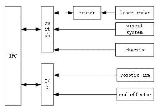
Note: IPC, industrial personal computer; I/O, i/o signal plate
Overall system structure of tomato harvesting robot.
6. Chassis. The dimensions of the chassis were designed based on the measured tomato row spacing with a length of 960 mm, width of 700 mm, and height of 320 mm. The chassis adopts a tracked design with highquality rubber embedded with Kevlar fibers, providing good skid resistance and toughness. When the control box, vision system, robotic arm, and harvested tomatoes are placed on the chassis, the design load capacity of the chassis is 80 kg. Since the ground of the greenhouse is not completely flat, the tracked chassis needs to have certain obstacle-crossing and climbing capabilities. The chassis is driven by a 48-V brushless DC motor, with a maximum obstacle-crossing height of 150 mm and a maximum climbing angle of 30°. The chassis is positioned 75 mm above the ground to prevent wear during obstacle crossing. A laser radar sensor, model RS-Helios-16P is installed on the chassis. The controller, produced by Shanghai Bintong Intelligent Technology Co., Ltd, is equipped with BITO's self-developed mapping and positioning software BSLAM, providing stable and reliable high-precision positioning data for the mobile robot, enabling autonomous navigation capability.
7. Tomato Collection Basket. A tomato collection box with dimensions of 500 mm × 350 mm × 200 mm is mounted on the chassis, placed at the front of the robot to accommodate the harvested tomatoes.
Vision System Design
Image Acquisition Method
The image acquisition method involves capturing 8 images for each cluster of tomatoes. These images are taken from different angles with respect to both the camera and the tomatoes' vertical plane, including 10°, 45°, 90°, 135°, and 170° directions. Additionally, one image is taken from each of the angles -45°, 0°, and 45° with respect to the horizontal position. The focus of this study was on capturing scenarios such as single tomato obstructed, single tomato without obstruction, multiple tomatoes obstructed, and multiple tomatoes without obstruction. Representative images are shown in Figure 8.
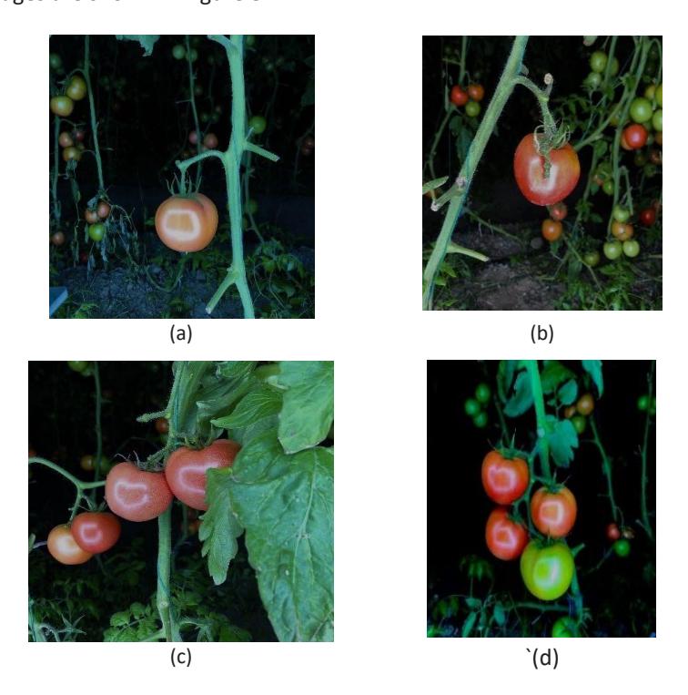
Image collection of four tomato growth forms: (a) single tomato without obstruction; (b) single tomato obstructed; (c) multiple tomatoes obstructed; (d) multiple tomatoes without obstruction.
Lighting System Design
In order to achieve uniform illumination over a large area and ensure clear capture of object contours by the camera, this study employed LED lights with bright-field parallel front lighting for the vision system's supplementary lighting. The study utilized the HSV color space segmentation method to segment the images based on selected thresholds. While keeping all conditions unchanged except for the light source color, tomatoes of the same pose are recognized to select white light as the supplementary light source for the vision system.
Tomato Night Image Denoising
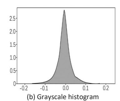
Light spots were generated on the surface of the fruit, accompanied by other noise, which has a certain impact on the subsequent tomato recognition and positioning. Therefore, further analysis of the noise types in the captured tomato images was required and appropriate denoising methods were selected for specific noise types for tomato image denoising. The RGB original image was converted to a grayscale image for analysis and it was found that the noise in tomato night images was more prominent than in daytime images. The difference image method [16] was used to analyze the noise type. The camera was fixed in the same position and two consecutive images in the same tomato image scene were taken as the subjects for the difference image analysis. The method performs subtraction operations on the channels of the two images. The result is shown in Figure 9(a) and the grayscale histogram of the result image is shown in Figure 9(b). Through comprehensive analysis of the difference image results, grayscale histogram, and original tomato night image, it was determined that the grayscale histogram conforms to Gaussian noise with a mean of 0. As the noise in this study is Gaussian noise, filtering methods were used to remove the noise from the image [17-19].
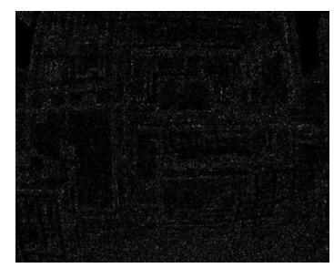
(a) The result diagram of the difference image method
Figure 9 Analysis of nighttime tomato image noise.
The peak signal-to-noise ratio (PSNR) provides an intuitive measure of the noise content in tomato images and is relatively easy to compute. The formula for PSNR is given by Eq. (1):
\[PSNR = 10 \log_{10} \frac{255^2}{\frac{1}{M \times N} \sum_{i=1}^{M} \sum_{j=1}^{N} [f(i,j) - \hat{f}(i,j)]^2}\] (1)
where f(i,j) is the pixel value of the original tomato image at position (i,j); \(\hat{f}(i,j)\) is the pixel value of the denoised tomato image at position (i,j) after denoising; and M and N are the dimensions (length and width) of the image, i.e., the image size is M × N.
Three tomato night images, denoted as a, b, and c, were selected as the experimental objects. These three images were converted to grayscale, and denoising was performed using both the guided filter and Gaussian filter denoising methods. The PSNR values for the denoised tomato images using both methods were calculated as displayed in Table 3.
| Image | Indicators | Guided filtering | Gaussian filtering | |
|---|---|---|---|---|
| Imaga | PSNR (dB) | 43.69 | 44.14 | |
| Image a | Run time (ms) | 1.87 | 0.53 | |
| Imaga h | PSNR (dB) | 44.65 | 45.26 | |
| Image b | Run time (ms) | 2.15 | 0.66 | |
| lmaga | PSNR (dB) | 42.64 | 43.17 | |
| Image c | Run time (ms) | 1.74 | 0.48 | |
Table 3 PSNR and time processed by two filtering methods.
It can be observed that the Gaussian filter provided better noise reduction for the tomato images in this study. However, it resulted in less clear preservation of the tomato edge contours. On the other hand, the guided filter better preserved the tomato edge contours.
In order to achieve both effective noise reduction and clear preservation of the tomato contours, this study proposes a filtering method that combines Gaussian filtering with guided filtering. In this method, the tomato image is first subjected to preliminary processing using a \(3 \times 3\) Gaussian filter kernel, which removes some Gaussian noise while preserving clear tomato contours, as shown in Figure 10(b). Subsequently, the processed image is further subjected to guided filtering, which removes the remaining noise while maintaining the clarity of the tomato contours, as shown in Figure 10(c).
The calculated peak signal-to-noise ratio for the denoised images using this proposed filtering method was 44.13 dB, which is slightly higher than the result of pure Gaussian filtering (43.17 dB). Moreover, the proposed method exhibited superior performance in preserving the clarity of the tomato contours compared to Gaussian filtering alone.
(a) Original (b) Gaussian filtering (c) Guide filtering
The noise reduction method used in this study.
YOLOv5+HSV Fusion Algorithm
To address the issue of low recognition accuracy in the original YOLOv5 algorithm, an improved YOLOv5+HSV fusion algorithm was adopted. YOLOv5 is combined with the HSV color space to extract mature red tomatoes from immature green tomatoes and the background, based on the characteristics of the HSV channels. This significantly reduced the misidentification rate and missed-detection rate of ripe tomatoes, especially in cases with occlusion and light spots, resulting in a substantial improvement in recognition accuracy. The HSV color space segmentation module was specifically designed to address occlusion and lighting issues, with HSV having a minor impact from lighting variations. The improved algorithm retains the advantage of fast recognition speed while enhancing the accuracy of tomato recognition.
The YOLOv5+HSV fusion object detection network, after incorporating the proposed method, is illustrated in Figure 11.
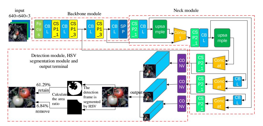
YOLOv5+HSV fusion target detection algorithm mature tomato recognition process.
Tomato Harvesting Robot Vision System Recognition
The detection box of the YOLOv5+HSV fusion algorithm is shown in Figure 12. Let point A have coordinates (, ) and point B have coordinates (, ). The two-dimensional coordinates of the tomato center point O can be represented as follows:
\[x_O = \frac{x_A + x_B}{2} \tag{2}\]
\[y_O = \frac{y_A + y_B}{2} \tag{3}\]
Here, represents the horizontal coordinate of the tomato center point and represents the vertical coordinate of the tomato center point.
Now it is necessary to obtain the corresponding three-dimensional coordinate information for the center position of the tomato fruit, i.e., the depth information of this two-dimensional coordinate point. The algorithm principle is illustrated in Figure 12.
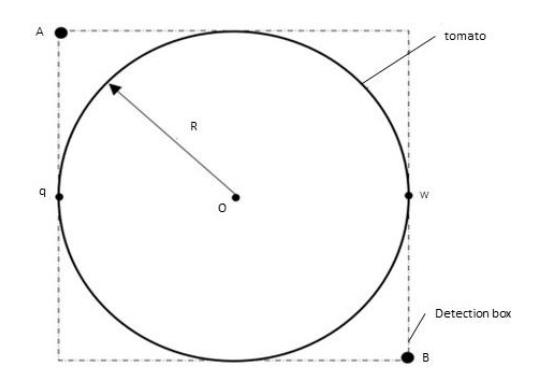
Tomato depth information calculation principle.
The detection box can be viewed as a square, where points q and w are the left and right intersection points of the tomato contour with the detection box, respectively. Point O represents the tomato center and R is the radius of the tomato. Combining with the ZED 2i stereo camera's intrinsic and extrinsic parameters, the grab() function is used to obtain one frame of the tomato image. The retrieveMeasure() function is used to retrieve the depth map obtained by the ZED 2i left camera, which is aligned with the image. Another retrieveMeasure() function is used to retrieve the three-dimensional point cloud data at points z and w on the RGBA color plane with coordinates (x, y, z) as well as the points on both sides of the tomato contour.
Let the coordinates of point q be (,,) and the coordinates of point w be (,,). Then the coordinates of the tomato center point O (X, Y, Z) can be represented as follows:
\[X = \frac{X_q + X_w}{2} \tag{4}\]
\[Y = \frac{Y_q + Y_w}{2} \tag{5}\]
\[Z = Z_q = Z_w \tag{6}\]
\[R = |X_q - X_w| = |Y_q - Y_w| \tag{7}\]
Setting of Communication between Vision System and Robotic Arm Control System
In this study, communication between the vision system and the robotic arm control system is established using TCP communication. The vision system is set to listen for instructions from the robotic arm control system. When the robotic arm control system issues a picking instruction, the vision system transmits the three-dimensional information of the nearest tomato center point and the size of the tomato to the robotic arm control system. Subsequently, the robotic arm control system controls the robotic arm's end effector to the specified position for grabbing.
Results and Discussions
Experimental Method
To validate the feasibility of the nighttime tomato harvesting robot, recognition, and grasping experiments were conducted, both during daytime and nighttime conditions. The experiments were carried out in the laboratory, simulating daytime and nighttime working conditions using artificial tomato models. The whole-machine recognition and grasping experiment during the day is shown in Figure 13, and the experiment at night is shown in Figure 14.
Daytime whole machine grasping test.
Nighttime whole machine grasping test.
During the experiments, the artificial tomato models were placed in different configurations and after grasping, they were placed in the nearby tomato collection basket. Multiple sets of grasping experiments were conducted and the following data were recorded for each set of experiments: total number of tomatoes, number of ripe tomatoes, number of correctly recognized tomatoes, number of successful grasps, recognition and localization time for individual tomato images, and average time for grasping a single tomato.
The configurations of the artificial tomatoes during the daytime are shown in Figure 15(a) and the configurations at nighttime are shown in Figure 15(b), including scenarios with single tomatoes without obstruction, single tomatoes with small-area obstructions, single tomatoes with large-area obstructions, overlapping red-red tomatoes, overlapping red-green tomatoes, stacked tomatoes, and overlapping with obstructions, among others.
Tomato placement during the daytime and nighttime.
Test Results
Relevant daytime test data are shown in Table 4. The relevant data of the nighttime test are shown in Table 5. From Table 4, it can be observed that the daytime recognition rate and recognition localization time were 93.72% and 12.77 ms, respectively. The success rate of grasping and the time for a single grasp were 87.78% and 15.99 s, respectively. From Table 5, it can be seen that the harvesting time during the nighttime simulation field test increased slightly compared to the daytime test, but the difference was not significant. The recognition rate and recognition speed of the visual system still remained at a high level, with a recognition rate of 93.36% and a recognition localization time of 12.97 ms. The success rate of grasping and the time for a single grasp were 87.55% and 17.26 seconds, respectively.
| Tomato placement | Number of total tomatoes | Number of ripe tomatoes | Number of correctly recognized tomatoes | Number of successful grasps | Recognition rate /% | Identification positioning time /ms | Grasp success rate /% | Single average grasp time /s |
|---|---|---|---|---|---|---|---|---|
| A | 10 | 10 | 10 | 10 | 100 | 12.62 | 100 | 15.07 |
| B | 10 | 10 | 10 | 10 | 100 | 11.84 | 100 | 16.37 |
| C | 10 | 10 | 8 | 7 | 80 | 13.43 | 70 | 16.73 |
| D | 26 | 26 | 25 | 22 | 96.15 | 12.15 | 84.62 | 14.84 |
| E | 28 | 20 | 19 | 18 | 95 | 13.92 | 90 | 15.36 |
| F | 34 | 26 | 24 | 22 | 92.31 | 11.23 | 84.62 | 17.14 |
| G | 27 | 27 | 25 | 23 | 92.59 | 14.18 | 85.19 | 16.43 |
| Average | \ | \ | \ | \ | 93.72 | 12.77 | 87.78 | 15.99 |
Table 4 Daytime grasping test speed and success rate.
Table 5 Nighttime grasping test speed and success rate
| Tomato placement | Number of total tomatoes | Number of ripe tomatoes | Number of correctly recognized tomatoes | Number of successful grasps | Recognition rate /% | Identify positioning time /ms | Grasp success rate /% | Single average grasp time /s |
|---|---|---|---|---|---|---|---|---|
| A | 10 | 10 | 10 | 10 | 100 | 12.41 | 100 | 16.88 |
| B | 10 | 10 | 10 | 10 | 100 | 13.76 | 100 | 17.59 |
| C | 10 | 10 | 8 | 8 | 80 | 11.54 | 80 | 15.63 |
| D | 29 | 29 | 27 | 24 | 93.10 | 14.17 | 82.76 | 16.71 |
| E | 34 | 28 | 27 | 23 | 96.43 | 12.95 | 82.14 | 16.95 |
| F | 37 | 32 | 29 | 26 | 90.63 | 13.14 | 81.25 | 17.37 |
| G | 33 | 30 | 28 | 26 | 93.33 | 12.85 | 86.67 | 17.26 |
| Average | \ | \ | \ | \ | 93.36 | 12.97 | 87.55 | 17.26 |
Note: A = single tomatoes without obstruction; B = single tomatoes with small-area obstructions; C = single tomatoes with large-area obstructions; D = overlapping red-red tomatoes; E = overlapping red-green tomatoes; F = stacked tomatoes; G = overlapping with obstructions.
Discussion
Through the whole-machine daytime and nighttime simulated field tests, it was observed that the visual system achieved a relatively high actual recognition and localization accuracy. When there was little or no occlusion, it could achieve a recognition rate close to 100% and accurately provide three-dimensional tomato coordinate information to the harvesting robot control system. However, under conditions of occlusion and overlap, the recognition rate and grasping success rate were lower. This could be attributed not only to the factors present during the daytime tests but also to the influence of factors such as temperature, humidity, and lighting during both the daytime and the nighttime tests. The visual recognition system based on YOLOv5+HSV algorithm proposed in this article improves both recognition accuracy and speed, effectively addressing the current issues of supplementary lighting and image noise reduction in nighttime harvesting robots. Although the harvesting robot's accuracy may be affected by environmental factors, it can harvest tomatoes at night, extending its working hours and thus increasing harvesting efficiency. In the face of complex greenhouse environments, it is inevitable that recognition and harvesting accuracy may be compromised. However, overall, the visual system performs well, meeting the requirements of rapid recognition and precise positioning of targets for tomato harvesting robots in this project. Our focus for the future will continue to be optimizing the visual system to reduce the impact of the environment on recognition accuracy. This study can serve as a reference for future research on nighttime tomato harvesting robots.
Conclusion
A nighttime greenhouse tomato harvesting robot was designed. Detailed designs were conducted for the chassis, control box, visual system, robotic arm, end effector, lifting mechanism, collection basket, and laser radar. Particular attention was given to the research and design of the visual system, including the study of supplementary lighting, lighting arrangement, visual elevation system, tomato dataset collection method, and three-dimensional localization of tomatoes. A YOLOv5+HSV visual recognition method suitable for both daytime and nighttime harvesting operations was proposed. Compared to the single YOLOv5 algorithm, this method effectively improves the accuracy of nighttime visual recognition, recognition speed, and positioning precision of harvesting robots. Consequently, it enhances the efficiency, accuracy, and success rate of harvesting for these robots. The recognition and grasping experiments of the harvesting robot in both daytime and nighttime conditions demonstrated that the visual system achieved a recognition rate of 93.72% and a recognition localization time of 12.77 ms during daytime tests, with a grasping success rate of 87.78% and an average grasping time of 15.99 s per tomato. In the nighttime simulated field tests, the visual system achieved a recognition rate of 93.36% and a recognition localization time of 12.97 ms, with a grasping success rate of 87.55% and an average grasping time of 17.26 s per tomato. The overall recognition rate and recognition speed of the visual system remained at a high level and the harvesting speed was relatively fast. The success rate and harvesting time for nighttime harvesting were only slightly different from those during the daytime, indicating that the visual recognition method based on YOLOv5+HSV, supplementary lighting system, and image noise reduction employed by the harvesting robot have shown significant effectiveness. Nighttime harvesting robots can effectively extend their working hours, thereby improving harvesting efficiency and addressing the current issues of slow harvesting speed and low efficiency in harvesting robots.
Acknowledgements
This work was supported by the Independent Innovation Fund of Agricultural Science and Technology in Jiangsu Province (CX(21)1007), Department of Agricultural Equipment Project (NZXB20210101). We thank Professor Qizhi Yang for his guidance in our work.
Compliance with Ethics Guidelines
Lei Liu, Qizhi Yang, Wenbing He, Xinyu Yang, Qin Zhou and M. Addy declare that they have no conflicts of interest or financial conflicts to disclose.
This article does not contain any studies with human or animal subjects performed by any of the authors.