
Introduction
The Semarang-Demak Toll Road, an important infrastructure project along the northern coast of Semarang City in Central Java, Indonesia, has been designated as a national strategic project. This project uniquely integrates a road embankment with a sea dike, addressing the dual needs of transportation and coastal protection. However, the area is characterized by soft soil deposits extending up to 40 meters below the seabed, which present significant geotechnical challenges, including slope instability and excessive settlement. Road embankment on top of the soft soil will cause problems such as slope instability and large settlement as mentioned in Vipulandan et al (2008), Chu et al (201), Almeida & Marques (2013), Susila & Agrensa (2015), Aspar & FItriani (2018), Rusdiansyah (2016), fulfill technical requirements, soil improvement is necessary. To meet technical requirements and ensure the stability and functionality of the embankment, soil improvement techniques are required.
The proposed soil improvement system incorporates bamboo mattresses, prefabricated vertical drains (PVD), highstrength woven geotextiles, and staged embankment construction. The bamboo mattresses act as a load-spreading platform, enhancing the bearing capacity of the soft subsoil during PVD installation and providing buoyancy to support construction equipment. PVDs accelerate consolidation by expediting the dissipation of excess-pore water pressure and increasing the undrained shear strength of the subsoil. Staged embankment construction is used to achieve minimum safety factor during each embankment stage. To accommodate the project's unique challenges, such as the 40-meter installation depth, high-discharge capacity PVDs were employed, learning from similar projects like Changi Airport and after conducting consultations with international geotechnical experts. High discharge capacity PVD is used to accommodate kinking/buckling and high lateral soil pressure due to the extra depth of the PVD as mentioned in various literature such as mentioned in Onoue (1988), Leo (2004), Indraratna (2010), Saowapakpiboon et al (2011), and Hamida et al (2014).
High-strength woven geotextiles were introduced to complement the bamboo mattresses during specific construction stages, addressing the tensile strength limitations of the bamboo connectors. While bamboo mattresses have been widely used in reclamation projects across Indonesia, their application in toll road construction in the Semarang-Demak project represents a novel approach. The innovative configuration employed in this project, where bamboo mattresses are arranged in a grid to allow PVD installation between grid lines, underscores the complexity and ingenuity of the design. What makes this research unique compared to the previous studies:
- 1. While other researches are focused on either of bamboo mattress and bamboo pile, few have incorporated PVD system in their design, as studied by Maruf et al (2023) and Sitharam et al (2021). This research investigates the effectiveness of a combined bamboo mattress and PVD system as an integrated ground improvement solution. By analyzing the bamboo mattress in combination with PVDs, it explores synergistic effects that haven't been well studied. Most prior works isolate these components, which might be overlook performance interactions.
- 2. In the literature, studies on the use of bamboo mattresses as basal reinforcement have typically been conducted on dry land. This research, however, evaluates the performance of the bamboo mattress system under seawater conditions. Testing the bamboo mattress system in a marine or tidal environment rather than on dry land adds significant novelty. The behaviour of natural materials like bamboo can differ considerably in wet or saline conditions, which is critical for coastal or reclamation projects
- 3. This study also includes analysis and results from monitoring data from a full-scale trial conducted under real field condition Including data from a full-scale field trial enhances the practical relevance and applicability of the research. Many studies stop at modelling or lab-scale tests, so field validation is a strong contribution to the engineering community.
While the study is fairly comprehensive and can be applied to other condition especially on dry land, findings and results of this study cannot be fully utilized if the bamboo mattress system is applied without using PVD.
In order to validate that the embankment design can be constructed successfully and achieves the expected performance, a full-scale trial embankment was implemented as part of the project. This paper provides an analysis of the data collected from the full-scale trial embankment implemented in this project that is provided with complete monitoring systems, such as Settlement Plate, Vibrating Wire Piezometer, Inclinometer, Extensometer, Total Pressure Cell, Strain Gauge, and Piezocone Cone Penetration Test (CPTu).
Full-scale Trial Embankment
Soil Conditions
The total length of Semarang-Demak Toll Road is 27 km. The project is divided into two sections. Section 1 is STA 0+000 to STA 10+394 and section 2 is STA 10+394 to STA 27+000. Trial embankment is located on Section 1 STA 4+200 to STA 4+600 as presented in Figure 1.
Location of the trial embankment.
Soil condition in the area is dominated by soft soil. The upper 5-20 m soil from seabed consists of very soft to soft silty clay with qc value 0-8 kg/cm2 and N-SPT ranges from 0 to 4. Below the upper layer is soft to medium stiff silty clay with qc 2-10 kg/cm2 and N-SPT from 4 to 10 which can be found up to 35 m below seabed. The deeper soil layer identified is stiff silty clay with N-SPT > 10. Value of qc and visualization of soil layer in the project area can be seen in Figure 2.
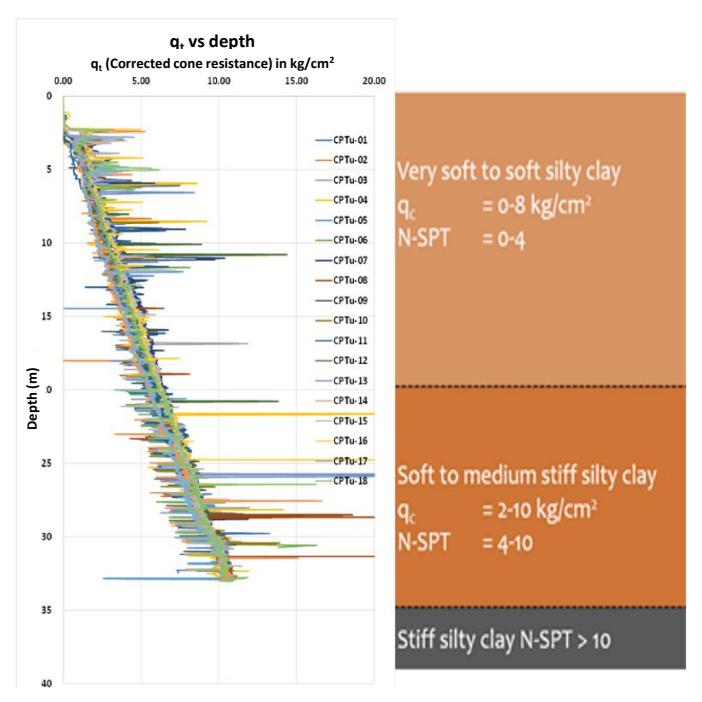
Soil layer of the project area.
Selected Soil Improvement
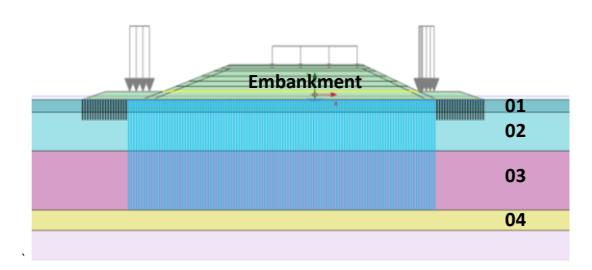
The initial soil improvement design integrates a 17-layer bamboo mattress placed on the original soil surface. The amount of layer was determined using early soil tests for shear strength of the soft soil and preliminary finite element method (FEM) analysis for stability. A schematic cross-section of this design is presented in Figure 3, illustrating the bamboo mattress as a load-spreading platform. Separator geosynthetics were applied above the mattress to ensure uniform load distribution. Geotubes and bamboo piles were installed around the perimeter to mitigate unwanted lateral movements during construction. This configuration not only stabilizes the subsoil but also allows heavy construction equipment, such as mandrel cranes for PVD installation, to operate safely.
The bamboo mattress provides buoyancy and reinforcement, making it a cost-effective alternative to conventional platform or floating pontoons. An illustration of bamboo mattresses is presented in Figure 4. Following the installation of the bamboo mattress, the platform was filled with a 3-meter embankment (Stage 1) to reach +1.2 m above Mean Sea Level (MSL). This stage facilitated the installation of PVDs, which were embedded to depths exceeding 40 meters to accelerate consolidation. Vertical pressure from mandrel cranes is estimated to be 44 kPa. Subsequently, a preloading embankment was constructed in six (6) additional stages, with a total height reaching 13.5 meters.). This value was determined based on the requirements of the Indonesian standard SNI 8460-2017, which specifies a load factor of 1.3 for permanent construction loads in stability assessments.
The base design height of the embankment, corresponding to the permanent load, is 7.5 meters. To incorporate the load factor, this height is multiplied by 1.3, resulting in an equivalent design height of 9.75 meters. Additionally, to account for the vertical displacement caused by long-term settlement under the permanent load, an estimated settlement value is added. This results in a total embankment height of approximately 13.5 meters being used in the FEA model to accurately simulate the loading and deformation conditions during and after construction.
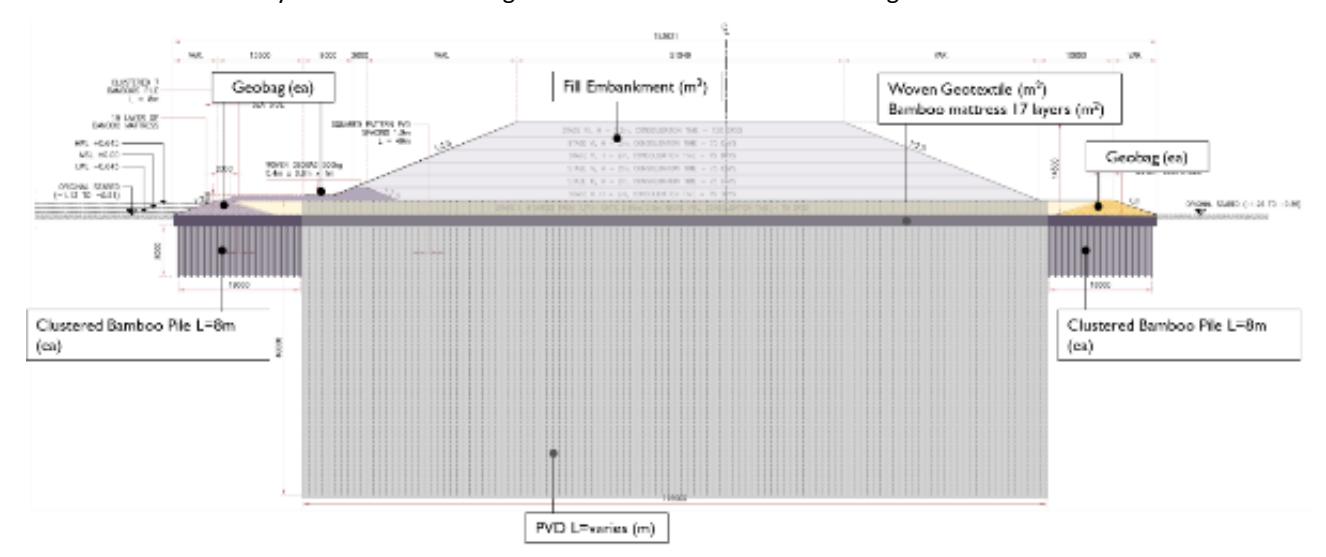
Schematics cross-section of the trial embankment reinforced using hybrid system.
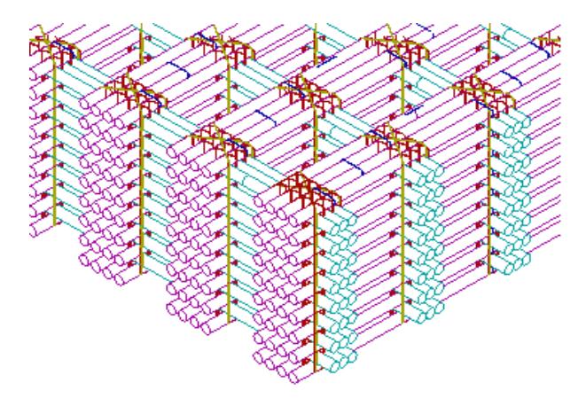
Schematic illustration of 17 layers of bamboo mattress and joint connections.
Bamboo Mattress Laboratory Testing
Bamboo has been widely used in Indonesia and other countries for soft ground improvement (Almedia & Marques (2013); Susila & Agrensa (2015) ; Rusdiansyah (2016); Jha,Choudhary & Gill (2010) ; Anusha & Kindo (2011), Waruwu & Susanti (2015) ; Waruwu & Halim (2017) ; Maulana et al (2018); Maulana et al (2019); Ma'Ruf (2017); Sitepu et al (2017); Lestari et al (2018); Widodo et al (2019); Ahirwar (2019); Krisnamurti & Nurtjahjaningtyas (2020); Suyuti & Hakim (2020)). Bamboo, when tied and assembled into a specific configuration, can be used as basal reinforcement beneath an embankment. In this application, the bamboo mat functions as a beam element rather than as a fiber or tensile component. To ensure the performance of the bamboo mattress, laboratory testing is conducted to determine its moment of inertia, which is critical for evaluating its flexural performance. Given the innovative application of bamboo mattresses in this project, extensive laboratory tests were conducted to validate their structural performance. Preliminary design parameters, such as axial stiffness (EA) and flexural rigidity (EI), were estimated based on methodologies by Irsyam et al. (2008) for narrow and limited wide embankment. The design incorporated a minimum bamboo diameter of 7 cm and grid configurations tailored for plane strain adjustments.
Bending and tensile tests on bamboo mattress samples were performed in compliance with the Indonesian National Standards (SNI) No. 03-3399-1994 for tensile tests and SNI No. 03-3399-1995 for flexural tests. The tests, conducted at the Ministry of Public Works and Housing laboratory, assessed the structural integrity of bamboo connections and the mattress system under loading conditions.
Bending Test Results
The bending test was conducted on a 17-layer bamboo mattress from sample BU37, with the mattress subjected to three (3) loading cycles. Figure 5, presents load-deflection readings from strain gauges placed on sample BU37. The bending test results demonstrated that the 17-layer bamboo mattress could withstand a maximum load of 1.8 tf with a deflection of 880.71 mm during the third loading cycle, as shown in Fgiure 6. No structural damage was observed, although nylon rope connections exhibited noticeable tension. The calculated flexural rigidity (EI) for the mattress system was 1140 kNm²/m, while the axial stiffness (EA) was determined to be 4511 kN/m, incorporating strain limits and system factors.
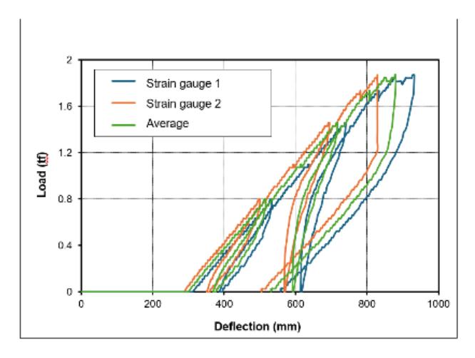
Load deflection readings from the bending moment test.
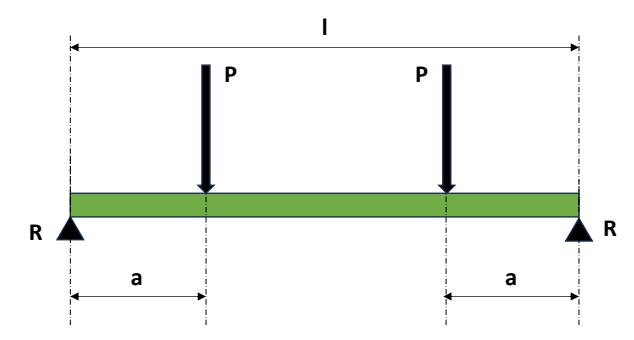
Simple beam on top 2 bearings with two-point loads.
Flexural rigidity (EI) and axial stiffness (EA) were recalculated based on the results of laboratory tests. The mattress is considered a simple beam on top of 2 bearings under two-point loads, as presented in Figure 6. Based on BU37 test results, the EI for BU37 is 1140 kNm<sup>2</sup>/m. Full documentation of the laboratory test can be seen in Figure 7.
Figure 7 Documentation of bamboo mattress laboratory test.
Tension Test Results
The average length of a single bamboo rod is 8 m, while the cross-sectional width of the toll road embankment exceeds 150 m. To create a continuous section, the bamboo mattress enclosing the embankment base must be connected using nylon ropes. In the laboratory test, the bamboo mattress had a length of 12 m. As noted previously, the nylon rope connections experience tension during loading. A tension test was conducted to determine the breaking capacity of the rope connections.
Figure 8, shows the documentation of the test on sample BU45, which was performed on a pair of bamboo rods connected by nylon rope. A strain gauge was attached to the test sample to monitor its load-deformation behavior. Figure 8(a), illustrates the test sample's condition before tension was applied. In contrast, Figure 8(b), depicts the sample condition after the tension load reached the ultimate breaking point at 256 kg-f and 240 mm of deformation. The load-deformation relationship from the tension test is presented in Figure 9. Each rope connection between two bamboo rods covers a tributary length of 8 m. Failure occurred at a strain level of 3%.
Figure 8 Tension test of nylon rope connection sample BU45, (a) before test, (b) after test.
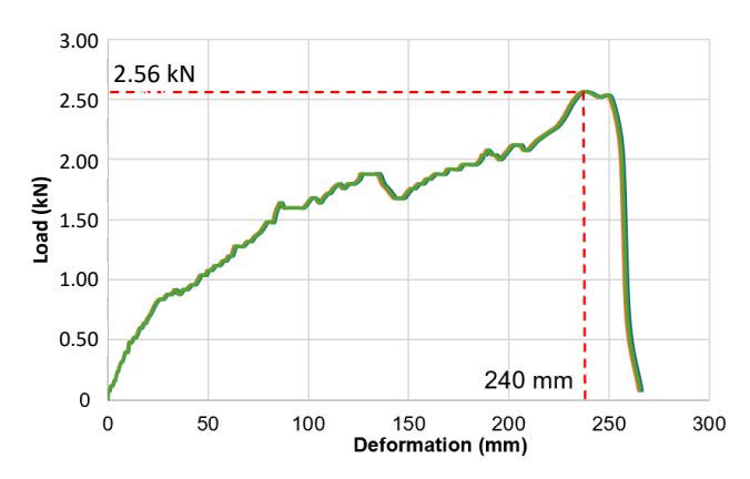
Figure 9 Load-Deformation result from tension test sample BU45.
Monitoring and Instrumentation
A comprehensive set of monitoring systems to evaluate the behavior of the embankment system was installed, including:
- 1. Settlement Plates: To measure vertical settlement at different points.
- 2. Vibrating Wire Piezometers: To monitor pore water pressure dissipation during consolidation.
- 3. Inclinometers: To detect lateral soil displacement.
- 4. Extensometers: To measure internal deformation within the embankment.
- 5. Total Pressure Cells: To assess stress distribution.
- 6. Strain Gauges: To measure strain in the bamboo mattress and geotextile layers.
The trial embankment was built in stages to simulate the actual construction sequence:
- 1. Stage 1: Construction of the bamboo mattress platform and initial 3-meter embankment.
- 2. Stage 2: Installation of PVDs and additional embankment layers.
- 3. Stage 3: Installation of high-strength geotextile above initial 3-meter embankment.
- 4. Stages 4 End of construction: Incremental preloading to reach the final height of 14 meters.
These construction stages are shown on Figure 10.
Documentations of the trial embankment construction: (a)Installation of bamboo mattress, (b) Installation of sand fill for first stage, (c) Installation of PVD using PVD crane and high strength geotextile.
In each stage, in-situ investigations, including Cone Penetration Tests (CPT), Deep Boring, and Piezocone Cone Penetration Tests (CPTu), were conducted to assess soil properties and validate consolidation progress.
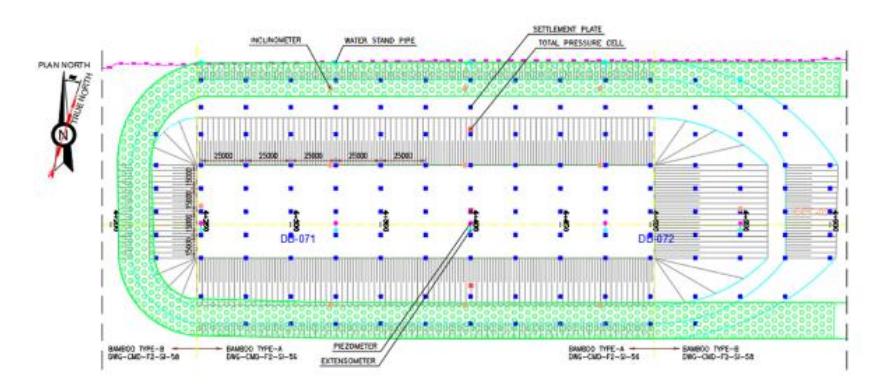
Layout of Geotechnical Instrumentation
Numerical Modeling for the Trial Embankment
Finite element analysis was conducted to assess the stability and safety factors of the trial embankment. The soil in the study area was modeled using the Soft Soil Creep (SSC) model, while the fill embankment was represented using the Mohr-Coulomb (MC) model. Interaction between bamboo mattress, bamboo cluster and existing soft soil is modelled in Finite Element Method (FEM). Each part of the basal reinforcement is modelled differently. Bamboo mattress is modelled using plate element, meanwhile bamboo cluster is modelled using node-to-node anchor. The reinforcement is effectively distributing embankment loads more uniformly onto the underlying soft soil, while simultaneously providing basal reinforcement. Additionally, the clustered bamboo pile elements act as a group of pile foundations, contributing to a significant increase in the overall bearing capacity of the existing soft soil." The SSC model (compared to the soft-soil model) was chosen to emulate excess settlement due to creep during the toll road's service time. The soil parameters utilized in the analysis are summarized in Tables 1, 2 and Figure 12. Figure 12 are obtained through parameter studies conducted from various field soil investigation such as Standard Penetration Test (SPT), Piezocone Cone Penetration Test (CPTu), Vane Shear Test (VST) and various laboratory test such as Triaxial Test (Unconsolidated-Undrained/UU), Pocket Penetrometer Test and Torvane Test. The amount of settlement and the safety factor at each embankment stage, as determined through numerical modelling in the initial Detailed Engineering Design (DED), are used as guidelines for the trial embankment. Results based on monitoring data are back-calculated to adjust the parameters used during the construction sequence.
Table 1 Soil parameters for FEM analysis (Detailed Engineering Design (DED)).
| Parameter | Name | 01. Very Soft to Soft Clay | 02. Very Soft to Soft Clay | 03. Soft to Medium Stiff Clay | Embankment | Unit |
|---|---|---|---|---|---|---|
| General | ||||||
| Depth | - | 0 - 5 m | 5 - 20 m | 20 - 35 m | - | m |
| Material model | - | Soft-Soil Creep (SSC) | Soft-Soil Creep (SSC) | Soft-Soil Creep (SSC) | Mohr Coulomb | - |
| Type of material behaviour | Type | Undrained (A) | Undrained (A) | Undrained (A) | Drained | - |
| Soil unit weight above phreatic level | unsat | 15.6 | 15.6 | 15.6 | 16.5 | kN/m3 |
| Soil unit weight below phreatic level | sat | 16 | 16 | 16 | 19 | kN/m3 |
| Initial void ratio | einitial | 2.00 | 2.1 | 2.5 | 0.5 | |
| Parameters | ||||||
| Compression Index | Cc | 0.71 | 0.8 | 0.8 | - | |
| Swelling index | Cs | 0.1 | 0.08 | 0.08 | - | |
| Creep Compression Index | Cα | 0.23 | 0.23 | 0.23 | ||
| Modified compression index | λ* | 0.1029 | 0.08415 | 0.09938 | - | - |
| Modified swelling index | κ* | 0.02899 | 0.01683 | 0.01988 | - | - |
| Young's Modulus | E | - | - | - | 18000 | kN/m2 |
| Cohesion (constant) | cref' | 0 | 0 | 10 | 1 | kN/m2 |
| Friction angle | ϕ' | 19 | 19 | 19 | 30 | o |
| Over-consolidation ratio | OCR | 1 | 1 | 1 | 1 | |
| Poission ratio | νur' / ν' | 0.15 | 0.15 | 0.3 | 0.3 | |
| Permeability in horizontal direction | kx | 9.80E-06 | 9.80E-06 | 9.80E-06 | 7.13 | m/day |
| Permeability in vertical direction | ky | 2.00E-05 | 2.00E-05 | 2.00E-05 | 7.13 | m/day |
| Parameter | Name | 01. Very Soft to Soft Clay | 02. Very Soft to Soft Clay | 03. Very Soft to Soft Clay | 04. Soft to Medium Stiff Clay | Unit | Unit |
|---|---|---|---|---|---|---|---|
| General | |||||||
| Depth | - | 0 - 1.5 m | 1.5 - 8 m | 8 - 22 m | 22 - 35 m | - | m |
| Material model | - | Soft-Soil Creep (SSC) | Soft-Soil Creep (SSC) | Soft-Soil Creep (SSC) | Soft-Soil Creep (SSC) | Mohr Coulomb | - |
| Type of material behaviour | Type | Undrained (A) | Undrained (A) | Undrained (A) | Undrained (A) | Drained | - |
| Soil unit weight above phreatic level | unsat | 15.6 | 15.6 | 15.6 | 16.5 | 16.5 | kN/m3 |
| Soil unit weight below phreatic level | sat | 16 | 16 | 16 | 19 | 19 | kN/m3 |
| Initial void ratio | einitial | 3.00 | 2.1 | 2.1 | 2.5 | 0.5 | |
| Parameters | |||||||
| Compression Index | Cc | 1.36 | 1.18 | 1.09 | 0.73 | - | |
| Swelling index | Cs | 0.08 | 0.08 | 0.05 | 0.06 | - | - |
| Creep Compression Index | Cα | 0.009 | 0.009 | 0.009 | 0.009 | - | |
| Modified compression index | λ* | 0.1466 | 0.1708 | 0.1527 | 0.09938 | - | - |
| Modified swelling index | κ* | 0.01737 | 0.02316 | 0.01401 | 0.01988 | - | - |
| Young's Modulus | E | - | - | - | - | 18000 | kN/m2 |
| Cohesion (constant) | cref' | 0 | 0 | 0 | 10 | 1 | kN/m2 |
| Friction angle | ϕ' | 19 | 19 | 19 | 19 | 30 | o |
| Over-consolidation ratio | OCR | 1 | 1 | 1 | 1 | 1 | |
| Poission ratio | νur' / ν' | 0.15 | 0.15 | 0.15 | 0.3 | 0.3 | |
| Permeability in horizontal direction | kx | 9.44E-05 | 9.44E-05 | 9.44E-05 | 9.44E-05 | 7.13E+00 | m/day |
| Permeability in vertical direction | ky | 4.72E-05 | 4.72E-05 | 4.72E-05 | 4.72E-05 | 7.13E+00 | m/day |
Table 2 Soil parameters for FEM analysis (Back Calculate).
Overview of Finite Element Method Model.
The friction angle of the normally consolidated (NC) soft marine clay, determined through laboratory testing and validated using empirical correlations, is 19°. Atterberg Limit tests indicate that the average plasticity index (PI) of the project area ranges from 30% to 70%. According to Terzaghi et al. (1996), these PI values correspond to the lower bound of the classification chart, as illustrated in Figure 13. The shear strength value highlights the relatively weak shear strength of the soil, which is critical to stability considerations.
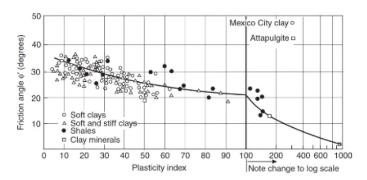
Values of peak friction angle ϕ' for clay of various compositions plotted against their plasticity index (After Terzaghi et al., 1996).
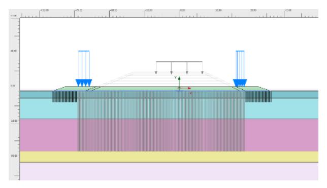
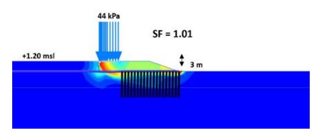
The analysis describes the methodology outlined in Section Monitoring and Instrumentation, employing bambooreinforced mattress parameters defined in Section Bamboo Mattress Laboratory Testing. The finite element model for Stage I is depicted in Figure 14. FEM analysis is carried out using PLAXIS. Deformation boundary used in this model are pinned boundary along the vertical axis, while using fixed boundary along the horizontal axis. Meshing size used on this analysis is "very fine" to better simulate deformation accurately within the assumption of large deformation model. Safety factor computations for Stage I, as shown in Figure 15, involved a mattress fill height of 3 meters under a 44 kPa mandrel crane load. The calculated safety factor (SF=1.01) was below the minimum required threshold of 1.20, necessitating design modifications
FEM Model for Stage 1.
Safety factor of stage I with bamboo parameters based on laboratory tests.
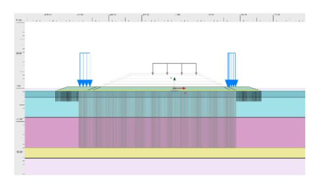
To address the stability concerns for stage 1, the mattress design was optimized by reducing the layers from 17 in the preliminary design to 13 and by incorporating a woven geotextile (Tult = 200 kN/m). The geotextile was introduced to accommodate the tension demands in Stage I, which are critical to platform stability. The revised FEM model and safety factor results are illustrated in Figures 16 and 17 respectively. The optimized configuration yielded a safety factor of 1.25, that fulfils the minimum design requirement.
FEM Model for modification in Stage 1.
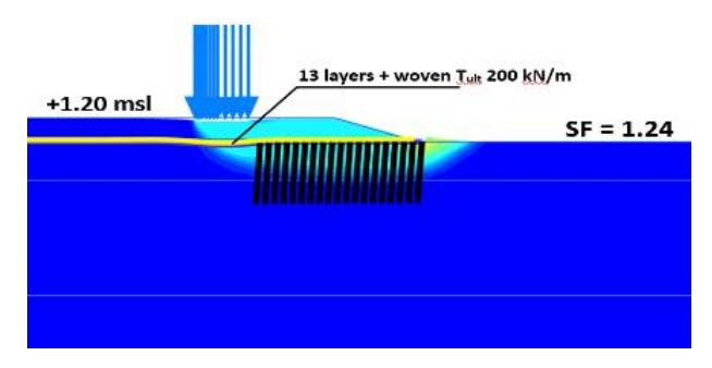
The safety factor of stage I with 13 layers of mattress and geotextile Tult 200 kN/m.
The reinforcement for increasing the stability of the embankment during preloading, the high-strength geotextile reinforcements (Tult = 1200 kN/m in the transverse direction and 1000 kN/m longitudinally) were installed at the crest of the embankment at +1.20 msl. The calculated safety factor for Stage VII, representing the highest embankment filling during preloading, is shown in Figure 18. The computed safety factor (SF=1.24) satisfies the design criteria during construction.
In long-term conditions, following soil consolidation, preloading removal, and the application of operational loads, the slope stability safety factor improved to SF=1.55, as illustrated in Figure 19. The safety factor exceeds the design requirement of 1.50, confirming the adequacy of the design for long-term performance.
Safety factor of stage VII (highest embankment fill during preloading).
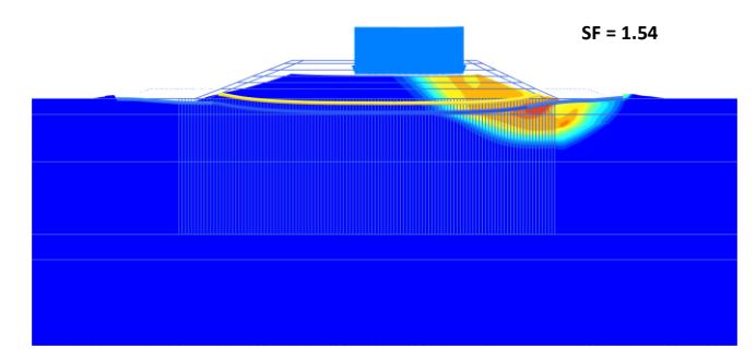
Safety factor for long-term condition (after consolidation, preloading removal, and operational load applied).
Comparison between Embankment Settlement from Design and from Field Observation
The trial embankment demonstrated the feasibility and effectiveness of combining traditional bamboo mattresses with modern reinforcements. Monitoring data confirmed significant reductions in pore water pressure and acceptable settlement rates. The inclusion of high-strength woven geotextiles improved tensile capacity, ensuring the stability of the embankment throughout construction.
Calculation of settlement of the embankment was also predicted using FEA for each stage of embankment loading that is followed by consolidation. Example of settlement at the center of embankment from initial Detailed Engineering Design (DED) for long term condition is presented in Figure 20. Results of settlement from FEA that was conducted for each stage of loading and consolidation were then compared to the field monitoring from settlement plates. The results of field monitoring from Stage I to Stage V were then used to adjust and to back calculated the FEA to revise and closely match the field data. The increase in shear strength from Stage I to Stage II is also shown in Figure 21. A significant rise is observed between the earlier stage of CPTu and Stage 2 CPTu, where the corrected cone resistance increases by up to 5 kg/cm². Example of back calculated settlement at the center of embankment after adjusting the consolidation parameters is presented in Figure 22.
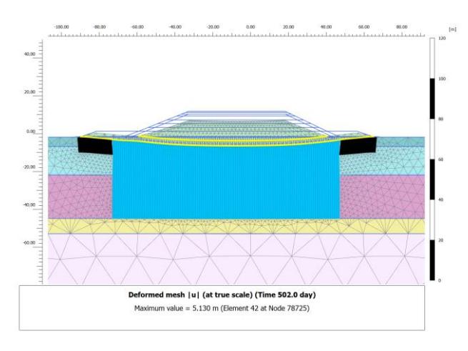
Figure 20 Deformed mesh for long-term conditions (Detailed Engineering Design (DED)).
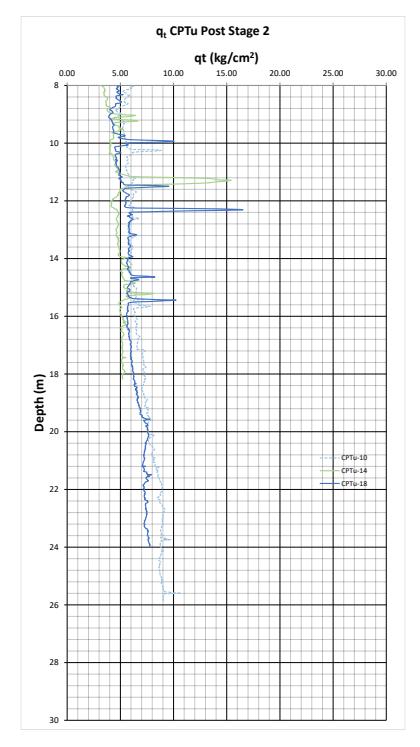
Figure 21 Shear Strength of the Soft Soil After Stage 2.
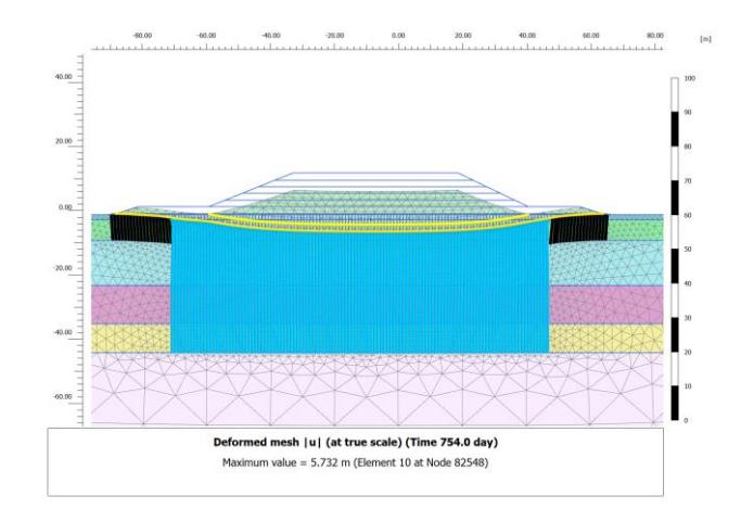
Figure 22 Deformed mesh for long-term conditions (Back Calculate).
Error! Reference source not found., shows FEA results of settlement calculation compared to field monitoring from Stage I to Stage V, they closely match each other. Finite Element Analysis (FEA) results validated the field performance, during construction and for long-term conditions. These findings highlight the innovative potential of combining traditional materials with advanced engineering practices in large-scale infrastructure projects.
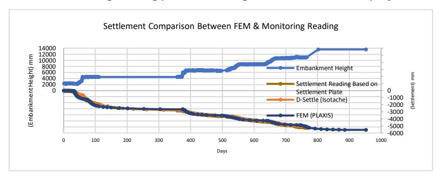
Figure 23 The results of monitoring and FEM.
The bamboo mat has been widely used in locations that remain saturated and are embedded in soil, such as sea dikes and breakwaters. Under these conditions—permanently saturated and soil-embedded—bamboo does not experience significant strength degradation. For safety considerations, in the numerical analysis, the bamboo mat is only considered effective up to Stage 4 (embankment height: 9 m). Beyond this stage, the bamboo mat is deactivated in the finite element model (FEM).
Based on back calculation results until the 5<sup>th</sup> stage of embankment, FEA is extrapolated until the final stage (6<sup>th</sup> stage) of the construction. The comparison between results of safety factor, settlement prediction and actual monitored settlement are shown in the table below.
| Stage | Actual Settlement Based on | Predicted Settlement using | Safety Factor Based on Back Calculation | |
|---|---|---|---|---|
| Monitoring Data (m) | FEA (m) | |||
| 1 (Platform) | -0.194 | -0.069 | 1.24 | |
| 2 | -2.994 | -3.000 | 2.05 | |
| 3 | -3.623 | -3.581 | 2.32 | |
| 4 | -4.436 | -4.297 | 2.32 | |
| 5 | -5.257 | -5.215 | 2.02 | |
| 6 | _ | -5 561 | 1 76 | |
Table 3 Back Calculation Result Based on Monitoring Data Until 5th Stage of Embankment.
Conclusions
A hybrid reinforcement that combines bamboo mattresses, high-strength woven geotextile, Prefabricated Vertical Drain (PVD) and staged embankment construction is selected to solve the shear strength and settlement problem for the full-scale trial embankment implemented in the Semarang-Demak Toll Road project. Mattress acts as platform to spread
initial embankment load uniformly into the subsoil and increase the bearing capacity, PVD accelerates consolidation and increases the undrained strength over time due to staged embankment construction, and high-strength woven geotextile provides tension capacity.
Laboratory tests were conducted as part of the trial embankment project for the Semarang-Demak toll road. These tests included bending and tension evaluations of the bamboo mattress system to determine the actual values of flexural rigidity (EI) and axial stiffness (EA). It was observed that the connections between bamboo elements constituted the weakest component of the system. The tensile strength of these connections was identified as the primary factor influencing the numerical parameters and failure criteria of the bamboo mattress.
During this study, several conclusions were drawn: The laboratory results revealed that the measured tension strength (EA) values were lower than the theoretical values initially used in the preliminary design. This discrepancy arose because conventional methods did not account for strain limitations at the connections. Due to the tensile capacity limitations of the bamboo mattress connectors, lateral loads during certain stages of embankment construction were transferred to high-strength woven geotextiles with superior tensile capacities.
The laboratory results also reveal that the measured flexural rigidity (EI) values were lower than the theoretical values initially used in the preliminary design. Similar to the tensile test results, the flexural test indicated that the connector is contributing significantly to overall flexural strength of the system.
Finite Element Method analysis was employed to reassess the safety factor of the toll road embankment. Based on the FEA results, adjustments were made to the preliminary design to improve stability and efficiency. The bamboo mattress system was optimized by reducing the number of layers from 17 in the preliminary design to 13, supplemented by the addition of high-strength woven geotextile with a tensile strength (Tult) of 200 kN/m. Furthermore, high-strength geotextile reinforcements with Tult of 1200 kN/m and 1000 kN/m were installed in the transverse and longitudinal directions, respectively, at the crest of the Stage I embankment at an elevation of +1.20 MSL.
- 1. The final design complied with the safety factor requirements, achieving a value of 1.25 during construction and 1.55 under long-term conditions, which fulfil the minimum design criteria. These modifications ensure that the bamboo mattress system, supplemented by geotextile reinforcements, can effectively sustain both construction and operational loads.
- 2. The final design after optimization, incorporating the revised bamboo mattress configuration and high-strength geotextile reinforcements, will be implemented in the full-scale trial embankment. This approach not only addresses the limitations identified in the preliminary design but also ensures long-term stability and performance under operational conditions.
Acknowledgements
Authors would like to acknowledge PT. Pembangunan Perumahan Semarang Demak (PT. PPSD) for the opportunity to obtain all necessary data in this study and BBPJN Jawa Tengah – D.I. Yogyakarta, Direktorat Jenderal Bina Marga Kementerian Pekerjaan Umum, Republik Indonesia.
Compliance with ethics guidelines
The authors declare they have no conflict of interest or financial conflicts to disclose.
This article contains no studies with human or animal subjects performed by authors.