
Introduction
The global energy landscape is undergoing a profound transformation, with renewable energy sources (RES) accounting for a growing share of the world's power generation. According to the World Energy Council's global scenarios, RES are expected to contribute nearly 30% of the world's electricity by 2025, with solar photovoltaic (PV) systems playing a leading role in this growth (Kober et al., 2020). Solar energy alone is predicted to become the largest source of electricity by 2050, providing over 20% of the world's power needs (Ritchie et al., 2024). This surge in solar energy adoption has created a demand for highly efficient, cost-effective power conversion systems capable of integrating photovoltaic power into both residential and grid-scale applications (Wenten et al., 2024). At the core of these PV systems are DC/AC inverters, which convert the direct current (DC) produced by PV panels into alternating current (AC) suitable for grid connection or standalone usage (Nallolla et al., 2023). In low-power PV applications, such as home solar installations, electric vehicles, and microgrid systems, finding the right balance between efficiency, cost, and reliability is crucial (Suvvala & Kumar, 2023). Traditional inverter topologies, like the Six-Switch Three-Phase Inverter (SSTPI), while providing robust performance, tend to be bulky, costly, and complex, making them less suitable for small-scale PV systems where cost and size constraints are significant (Farajdadian et al., 2024). In this context of increasing demand for cleaner and smarter energy solutions, optimizing the design and operation of DC/AC inverters becomes a critical factor in ensuring efficient, reliable, and economically viable PV systems. Reduced switch count topologies offer a promising pathway toward this goal, especially in small-scale applications where space and cost constraints are dominant.
2Research Laboratory on Renewable Energies & Electric Vehicles (RELEV) University of Sfax, ENIS, P.O. Box 1173, 3038 Sfax, Tunisia
Reduced structure inverters, such as the Three-Switch Three-Phase Inverter (TSTPI) and the Four-Switch Three-Phase Inverter (FSTPI), have emerged as compelling alternatives (Baviskar et al., 2023). These topologies utilize fewer components, offering substantial savings in terms of cost and space (Alshahrani et al., 2024). For instance, adopting TSTPI instead of the conventional SSTPI can reduce the number of switches by 50%, leading to lower material costs and simplified cooling requirements (Dewi et al., 2024). However, despite these advantages, reduced structure inverters face challenges in maintaining performance, particularly in controlling torque oscillations and managing harmonic distortions, which can adversely affect overall system efficiency (Vemparala et al., 2024). To address these challenges, Direct Torque Control (DTC), a well-established strategy in motor drive applications, is employed to optimize the performance of both TSTPI and FSTPI (El Badsi et al., 2018). DTC is recognized for its fast dynamic response, reduced reliance on motor parameters, and ability to minimize torque ripple, making it an effective candidate for controlling reduced structure inverters in low-power PV systems (Rhouma & Hamouda, 2020). By implementing DTC, the operational efficiency of these inverters can be enhanced without significantly increasing complexity (Rhouma & Hamouda, 2020; Kumar et al., 2021).
In this paper, we present a comparative study of DTC-controlled TSTPI and FSTPI inverters specifically designed for lowpower PV applications. A novel DTC strategy is developed and adapted for the TSTPI topology to enhance the precision of electromagnetic torque and stator flux control. The study employs advanced simulation tools in MATLAB/Simulink, as well as experimental validation using the dSPACE1104 real-time platform to ensure the credibility of the results. Key performance metrics-such as electromagnetic torque ripple, total harmonic distortion (THD) of stator current, and operational efficiency-are carefully evaluated to assess the effectiveness of the proposed strategies. This dual validation approach supports the robustness and real-world applicability of the proposed control scheme.
The results of this analysis indicate that both TSTPI and FSTPI are viable candidates for low-power PV systems, providing significant benefits in terms of cost and size without compromising performance. With the renewable energy market projected to grow at a 7.9% CAGR from 2021 to 2028, driven largely by innovations in energy storage and power conversion technologies, the insights provided in this study are timely and relevant for engineers and researchers working toward the next generation of inverter systems.
Overview of Induction Motors (IMs) and DTC
IMs in Low-Power Domestic Applications
IMs play a vital role in various low-power domestic applications, particularly in household appliances such as fans, washing machines, and small pumps. Their capability to operate efficiently on alternating current (AC) makes them suitable for direct integration with RES, particularly solar photovoltaic (PV) systems.
Key Characteristics Relevant to Domestic Applications:
- 1. Efficiency:IMs are renowned for their robust efficiency in low-powerapplications, which is critical for maximizing energy savings in residential settings.
- 2. Simplicity and Cost-effectiveness: The straightforward design of IMs, especially squirrel cage motors, ensures cost-effectiveness and ease of maintenance, which are essential attributes for consumer appliances.
- 3. Compatibility with Renewable Energy: The adaptability of IMs to work with DC/AC inverters facilitates their effective utilization of low-voltage AC generated from PV systems.
DTC for IMs
DTC has emerged as an effective strategy for controlling IMs in low-power domestic applications, particularly those powered by renewable energy sources. DTC enables precise regulation of both torque and flux, resulting in enhanced performance and efficiency.
Key Features of DTC in Domestic Applications:
1. Rapid Response: DTC provides quick adjustments to the motor's torque output, which is particularly advantageous in applications subject to variable load conditions, such as household appliances that frequently cycle on and off.
- 2. Minimized Torque Ripple: DTC effectively reduces torque ripple, leading to smoother motor operation and improved user comfort in applications like ceiling fans or washing machines.
- 3. Integration with Reduced Structure Inverters: When combined with reduced structure inverters, DTC optimizes motor performance while minimizing system complexity and cost. This integration is especially pertinent for residential setups, where space and budget constraints are significant considerations.
The Role of Reduced Structure Inverters
Reduced structure inverters, including the Three-Switch Three-Phase Inverter (TSTPI) (Nouira El Badsi, El Badsi, & Masmoudi, 2018) and the Four-Switch Three-Phase Inverter (FSTPI), are particularly advantageous for applications in low-power domestic settings. They necessitate a low direct current (DC) input, typically supplied by solar PV panels, making them ideal for seamless integration with renewable energy systems
Benefits of Utilizing Reduced Structure Inverters:
- 1. Cost and Space Efficiency: The design of reduced structure inverters allows for a substantial reduction in material costs and space requirements, effectively addressing constraints often encountered in residential environments.
- 2. Simplified Cooling Needs: With fewer switches and components, these inverters demand less complex cooling systems, further enhancing their suitability for home applications.
- 3. Sustainability and Energy Savings: By enabling the direct utilization of solar energy to power IMs in household appliances, these inverters contribute to a more sustainable energy ecosystem, fostering energy independence and reducing reliance on conventional grid power.
The integration of IMs, DTC, and reduced structure inverters presents a compelling solution for improving the efficiency and sustainability of low-power domestic applications powered by RES. As the demand for energy-efficient appliances continues to rise, this approach represents a proactive strategy for embedding clean energy technologies into everyday life.
Efficiency and Sustainability: Evaluating B3 and B4 Inverter Topologies for Solar-Powered IM Control Under DTC
Energy Efficiency in Solar-powered Applications
In PV systems, particularly in low-power applications like residential setups and micro-grids, efficiency is critical. Both the B3 and B4 inverter topologies, which use fewer switches, offer significant improvements in terms of reducing losses.
Reduced Switching Losses: B3 and B4 topologies, by design, reduce the number of active switches, thereby decreasing switching and conduction losses (Ouarda et al., 2014; Badsi et al., 2021; Tarusan et al., 2022; Patel & Pandya, 2022; Badsi & Badsi, 2025).
When applied in DTC of induction motors (IMs), these topologies demonstrate lower power consumption, particularly in partial load conditions typical of solar-powered applications. The B3 topology, with three switches, has been found to reduce power losses by up to 25%, while the B4 reduces losses by around 15% compared to conventional six-switch inverters (Deepak et al., 2023; Elgbaily, Anayi, & Packianather, 2022; Kakodia, Giribabu, & Ravula, 2022; Samithas, Balachandran, & Selvarajan, 2024). An overview of reduced structure inverters is provided in Table 1.
Sustainability and Material Efficiency
Compact structure inverters, such as B3 and B4, not only improve efficiency but also enhance sustainability by minimizing the material required for production.
- 1. Reduction in Components: With fewer switches, the B3 and B4 topologies use less silicon and other semiconductor materials. This contributes to more sustainable production processes, lowering the carbon footprint associated with manufacturing.
- 2. Simplified Cooling Systems: Since fewer components generate less heat, these topologies simplify cooling requirements, reducing the overall system size and power consumption dedicated to thermal management.
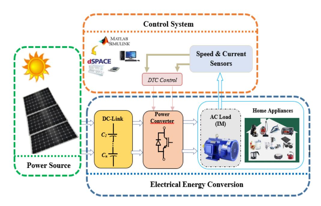
General diagram of the studied system.
Table 1 Overview of compact structure voltage source inverters (VSI).
| FSTPI (B4-VSI) | TSTPI (B3-VSI) | |
|---|---|---|
| 4switches | 3 switches | |
| Architecture | (2 legs, 2 switches per leg). | (1 leg, 1 switch per leg). |
| Connection | 2 phases connected to 2 legs, with the 3 rd phase connected to neutral. | Each phase connected to two legs (delta configuration). |
| Applications | Low-cost motor drives, photovoltaic systems (PV). | Basic low-power applications, Appliances, RES. |
VSI Based On FSTPI-Topology
FSTPI States and Active Voltage Vectors
The FSTPI topology is also known as a four-switch inverter (B4), which is a reduced-switch version used in motor drive applications(Figure 2).
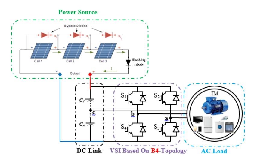
VSI based on FSTPI-topology.
\(S_1\)\(V_{s}\)\(S_2\)\(V_{dc}\)\(V_{dc}\)\(V_{dc}\)\(V_{dc}\)\(V_{dc}\)0 0 \(V_1\)\(2\sqrt{6}\)\(2\sqrt{2}\)6 6 \(V_{\underline{dc}}\)\(V_{dc}\)\(V_{d\underline{c}}\)0 1 0 \(V_2\)2 \(2\sqrt{6}\)\(2\sqrt{2}\)\(V_{dc}\)\(V_{dc}\)\(V_{dc}\)\(V_{dc}\)\(V_3\)1 3 \(2\sqrt{6}\)\(2\sqrt{2}\)\(3V_{dc}\)\(V_{dc}\)\(V_{dc}\)0 0 \(V_4\)1
Table 2 States of the IGBTs of the FSTPI and the Corresponding Vs.
Vs is the voltage vector defined in the reference frame \((\alpha,\beta)\) by the two components V\(\alpha\)s and V\(\beta\)s. The different combinations of the two states (S1 and S2) allow us to define four voltage vectors Vs (from V1 to V4) generated by the FSTPI.
Table 2 summarizes the states of the IGBTs of the FSTPI and the corresponding voltage vectors. The representation of the different voltage vectors Vs in the plane (\(\alpha\), \(\beta\)) is illustrated in Figure 3. The four voltage vectors are active, with two pairs equal in amplitude and shifted by \(\frac{\pi}{2}\).
Regarding the FSTPI, we have identified three major constraints that complicate the synthesis of the localization table for any DTC strategy intended for the IM command:
- 1. Reduced Number of Active Voltage Vectors: The FSTPI generates only four active voltage vectors, unlike the six generated by the SSTPI. This limits the degrees of freedom necessary to meet the proposed control rules.
- 2. Synthesis of Zero Voltage Vectors: Given that only four active vectors are available, it is necessary to synthesize zero voltage vectors by combining two opposite active vectors.
- 3. Amplitudes of Voltage Vectors: The amplitudes of the four active voltage vectors are equal in pairs, with a notable ratio of \(\sqrt{3}\), which may influence the control behavior.
Aside from the localization table, the implementation scheme for DTC strategies with uncontrolled switching frequency, dedicated to the FSTPI-IM association, remains the same as that of the DTC strategies intended for the TSTPI-IM association (Dutta & Panda, 2024).
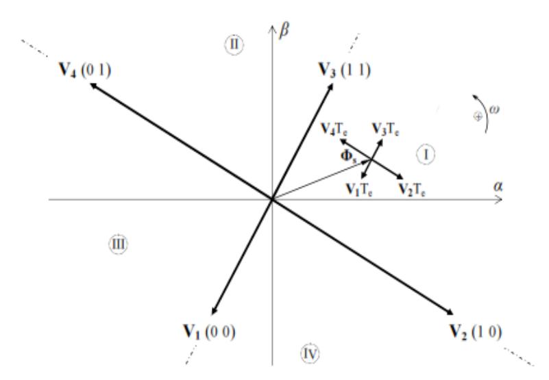
Figure 3 V<sub>s</sub> generated by the FSTPI.
DTC Strategy for Implementing Intrinsic Voltage Vectors Generated by the FSTPI
This is a DTC strategy dedicated to controlling the FSTPI-IM association, based on dividing the \((\alpha, \beta)\) plane into four sectors (I to IV) delineated by the four active voltage vectors illustrated in Fig.3. Referring to previous studies (Ouarda, El Badsi, & Masmoudi, 2018; Ammar, Benakcha, & Bourek, 2017; Ouarda, El Badsi, & Masmoudi, 2016; El Badsi, Bouzidi, & Masmoudi, 2012), the selection table has been synthesized by selecting the appropriate voltage vectors (V<sub>1</sub>
to V4), taking into account the sectors where the stator flux vector Φ is located and the combinations ( , Φ) representing the outputs of the hysteresis regulators forΦand electromagnetic torque. The localization table for such a strategy is provided in Table 3 (El Badsi, Bouzidi, & Masmoudi, 2012; Masmoudi, El Badsi, & Masmoudi, 2013).
| 𝒄𝝉 , 𝒄𝝋 | (+1 +1) | (+1 -1) | (-1 -1) | (-1 +1) |
|---|---|---|---|---|
| Sector I | 𝑉3 | 𝑉2 | 𝑉1 | 𝑉4 |
| Sector II | 𝑉4 | 𝑉3 | 𝑉2 | 𝑉1 |
| Sector III | 𝑉1 | 𝑉4 | 𝑉3 | 𝑉2 |
| Sector IV | 𝑉4 | 𝑉1 | 𝑉4 | 𝑉3 |
VSI based on TSTPI-topology
TSTPI topology refers to an even further reduced version of the inverter, also known as a three-switch inverter (B3) (Nouira El Badsi, El Badsi, & Masmoudi, 2018). The B3 topology reduces the number of active switches compared to both the B6 and B4 topologies(Masmoudi, El Badsi, & Masmoudi, 2013).
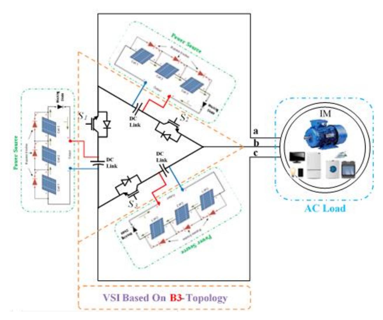
VSI based on TSTPI-topology.
Comparing different 3-Φ power converter topologies based on the number of power switches highlights the trade-offs between complexity, cost, performance, and control flexibility. Below, in Table 4 a comparison of common 3-Φ converter topologies, focusing on how they differ in terms of the number of switches used (Badsi & Badsi, 2025; Nouira El Badsi & El Badsi, 2025).
| Table 4 | Comparison of Different 3-Φ VSI in Terms of Power Switches. |
|---|
| VSI Type | Active Switches | Diodes | DC-Link (Capacitors) | Switching States | Active Vectors |
|---|---|---|---|---|---|
| FSTPI | 4 | 4 | 2 | 4 | 4 |
| TSTPI | 3 | 3 | 3 | 3 | 3 |
TSTPI States and Active Voltage Vectors
Table 5 States of the IGBTs of the TSTPI and the Corresponding Vs.
| 𝑺𝟏 | 𝑺𝟐 | 𝑺𝟑 | 𝒗𝒂𝒔 | 𝒗𝒃𝒔 | 𝒗𝒄𝒔 | 𝑽𝜶𝒔 | 𝑽𝜷𝒔 | 𝑽𝒔 |
|---|---|---|---|---|---|---|---|---|
| 1 | 1 | 0 | 0 | 𝑉dc | −𝑉dc | 0 | √2𝑉𝑑𝑐 | 𝑉1 |
| 0 | 1 | 1 | −𝑉dc | 0 | 𝑉dc | −√3⁄2𝑉𝑑𝑐 | 𝑉𝑑𝑐 − √2 | 𝑉2 |
| 1 | 0 | 1 | 𝑉dc | −𝑉dc | 0 | √3⁄2𝑉𝑑𝑐 | 𝑉𝑑𝑐 − √2 | 𝑉3 |
It is noteworthy that the TSTPI inverter, supplying a 3-Φ inductive load, generates only three state combinations (S1, S2, S3) equal to (1, 1, 0), (0, 1, 1), or (1, 0, 1), regardless of the control combinations applied (S1, S2, S3).
TSTPI-DTC Implementing Intrinsic and Virtual Voltage Vectors
The DTC strategy is founded on the principles established in Takahashi's conventional DTC strategies (which involve 6 sectors and 6 vectors). Specifically, the synthesis of the localization table for the current strategy is based on the following two approaches:
- 1. The use of both intrinsic and fictitious voltage vectors.
- 2. The subdivision of the (α, β) plane into six sectors.
Referring to Figure 5, the six sectors where ( = à) are centred around the intrinsic voltage vectors (V1, V2, and V3) and fictitious vectors (V12, V23, and V31).The identification of the sector "′′ containing the stator flux vector ∅ is completed by considering the following inequalities:
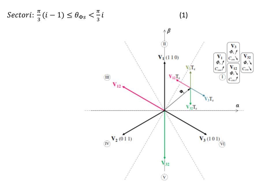
Vs generated by the TSTPI.
Additionally, Figure 5 illustrates the scenario where the flux vector Φ is located in Sector I (0 ≤ Φ < 3 ).
In this scenario, the control combinations ( = ±1, = ±1) can be achieved by applying the following voltage vectors:
\[\begin{cases} V_{1}pour\ (c_{\phi}=+1,c_{\tau}=+1\\ V_{3}pour\ (c_{\phi}=+1,c_{\tau}=-1\\ V_{32}pour\ (c_{\phi}=-1,c_{\tau}=-1\\ V_{12}pour\ (c_{\phi}=-1,c_{\tau}=+1\end{cases}\]
By adopting the same approach for the remaining five sectors, we obtain the location table corresponding to the TSTPI-DTC strategy, as shown in Table 6.
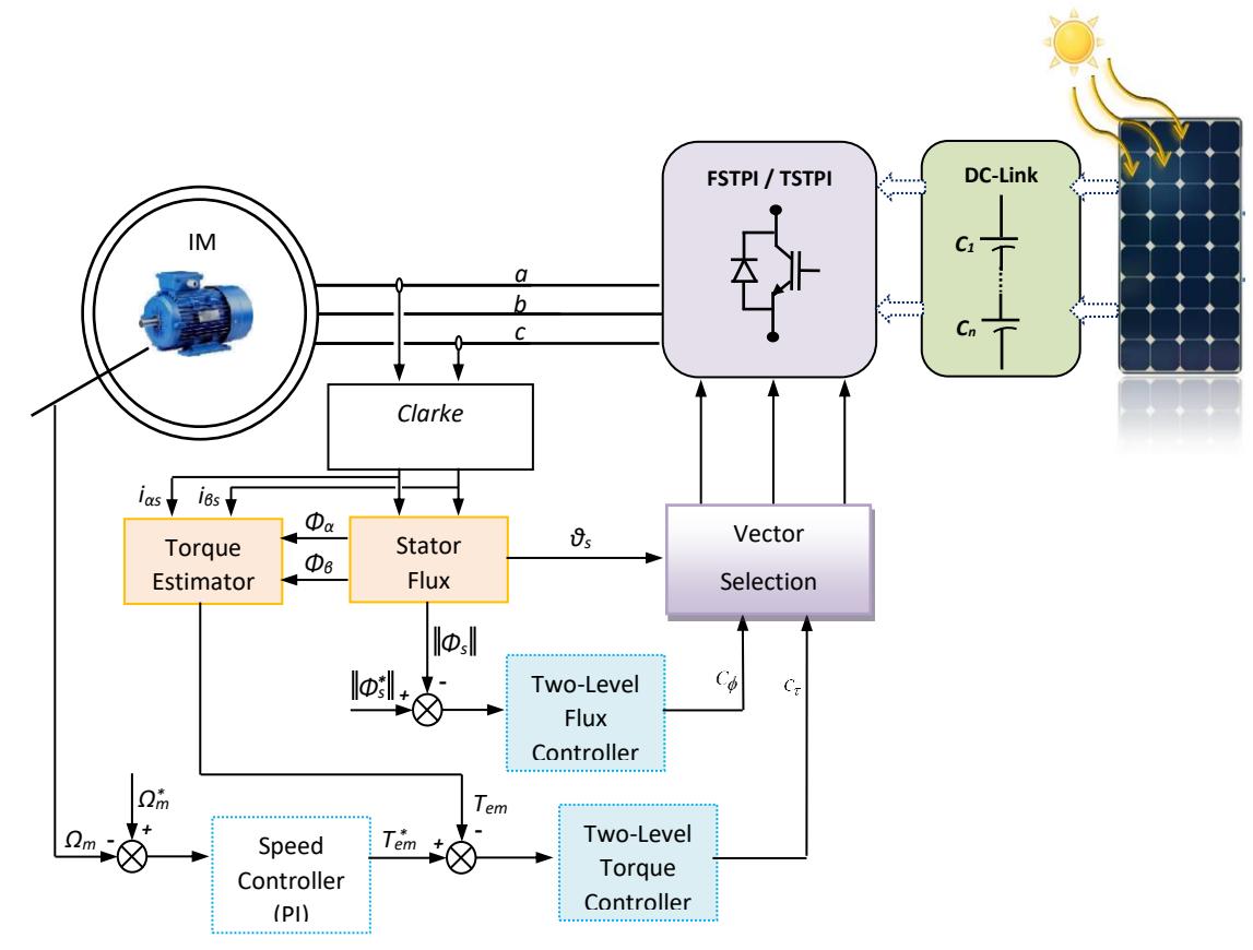
Figure 6 DTC scheme shared by FSTPI & TSTPI VSI.
Table 6 Selection Table for the Novel TSTPI-DTC Strategy.
| \(c_{\Phi}, c_{\tau}\) | (+1 +1) | (+1 -1) | (-1 -1) | (-1 +1) |
|---|---|---|---|---|
| Sector I | \(V_1\) | \(V_3\) | \(V_{32}\) | \(V_{12}\) |
| Sector II | \(V_{21}\) | \(V_{31}\) | \(V_3\) | \(V_2\) |
| Sector III | \(V_2\) | \(V_1\) | \(V_{13}\) | \(V_{23}\) |
| Sector IV | \(V_{32}\) | \(V_{12}\) | \(V_1\) | \(V_3\) |
| Sector V | \(V_3\) | \(V_2\) | \(V_{21}\) | \(V_{31}\) |
| Sector VI | \(V_{13}\) | \(V_{23}\) | \(V_2\) | \(V_1\) |
Comparative Study of FSTPI-DTC and TSTPI-DTC Strategies Based on Simulation and Experimentation
In order to objectively evaluate these strategies, this comparative study relies on both numerical simulations (Matlab/Simulink) and practical experiments. The use of simulations allows for precise modeling of system behavior in various scenarios, while reducing the costs and time required for initial testing. At the same time, real-world experiments validate the results obtained through simulation and account for complex phenomena such as disturbances and system inaccuracies.
Figures 7 and 8 presents a screenshot of the graphical simulation implementation of the Direct Torque Control (DTC) algorithm for a three-phase induction motor using the Matlab/Simulink environment, interfaced with the dSPACE 1104 real-time platform. The two sub-figures illustrate the respective DTC implementations:
- 1. corresponds to the FSTPI-DTC structure, and
- 2. to the TSTPI-DTC structure.
These graphical models were used to conduct simulations and to generate the control signals in the experimental setup, ensuring consistency between both environments.
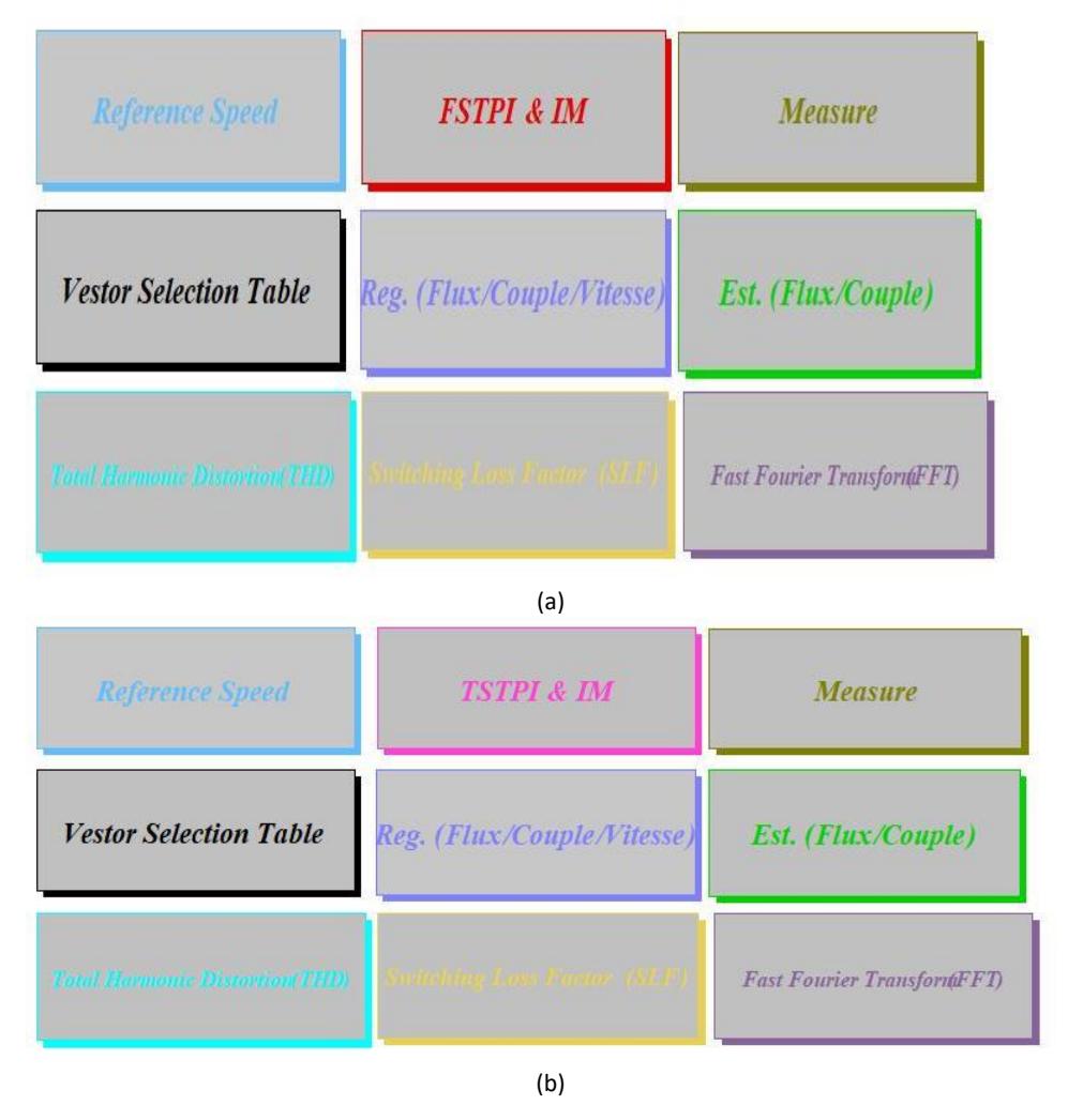
Screenshot of the graphical simulation code of DTC algorithm for a 3-Φ induction motor implemented using Simulink and dSPACE 1104 platform. Legend 1: (a) FSTPI-DTC, (b) TSTPI-DTC.
This combined approach (simulation and experimentation) enables us to compare the two strategies based on several criteria, including the precision of torque and magnetic flux control, the reduction of torque ripples, the implementation complexity, and energy efficiency. The ultimate goal is to identify the strengths and weaknesses of the FSTPI-DTC and TSTPI-DTC strategies and determine their optimal application areas.
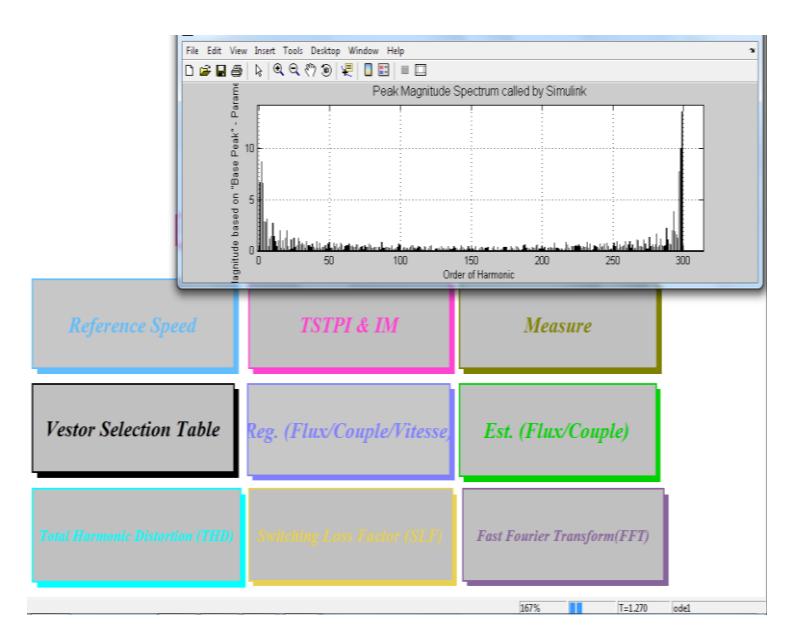
Harmonic Analysis of Stator Current under DTC Control Using Simulink FFT Tools.
Results
The comparative analysis between the FSTPI-DTC (Figure 9 a1-d1 and Figure 10) and TSTPI-DTC (Figure 9 a2-d2 and Figure 11) strategies reveals key insights into their respective performances in terms of torque control, harmonic distortions, and energy efficiency. The results obtained through both simulation and experimentation highlight the strengths and limitations of each topology, providing a comprehensive evaluation for their applications in solar-powered systems.
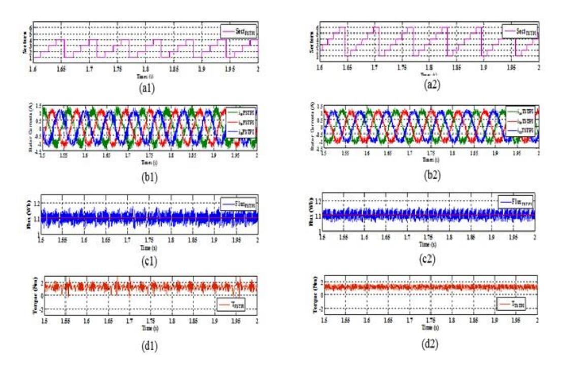
Numerical simulation results of DTC strategy. Legend 1: (a) sector sequence, (b) stator current, (c) stator flux,(d) electromagnetic torque Tem. Legend 2: (1) FSTPI-DTC, (2) TSTPI-DTC.
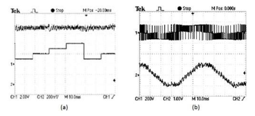
Experimental results of FSTPI-DTC strategies: (a) sector succession and electromagnetic torque, (b) a-phase stator current with a-phase voltage.
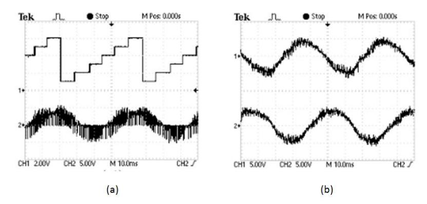
Experimental results of TSTPI-DTC strategy: (a) sector succession and leg-current, (b) a- and b-phase stator current.
Discussion
Torque Ripple and Control Precision
One of the most critical factors in DTC strategies is the ability to minimize torque ripple while maintaining high control precision. The simulations (Figure 9 a2-d2) show that the TSTPI-DTC strategy, with fewer switching vectors, experiences slightly higher torque ripple compared to the FSTPI-DTC strategy (Figure 9 a1-d1).
This can be attributed to the reduced number of active voltage vectors available in the TSTPI topology, which limits the control flexibility in stabilizing torque oscillations. Despite this limitation, the TSTPI-DTC still provides acceptable performance for low-power applications, particularly in scenarios where cost and space efficiency are more important than torque ripple minimization.
On the other hand, the FSTPI-DTC strategy, with its four switching states, offers improved torque control with lower ripple. This makes the FSTPI-DTC strategy a more suitable choice for applications where smoother motor operation is required, such as in household appliances powered by renewable energy systems.
Harmonic Distortion and Power Quality
Another key performance metric is Total Harmonic Distortion (THD), which directly impacts power quality in PV systems. Both the FSTPI and TSTPI inverters introduce higher THD. However, the experimental results indicate that the FSTPI-DTC (Figure 10) strategy generally achieves better performance with lower harmonic distortion than the TSTPI-DTC (Figure 11) strategy. This is particularly important in residential PV systems, where maintaining good power quality is crucial to ensure the proper functioning of household appliances and minimize interference with other electronic devices.
Despite the slightly higher THD observed in the TSTPI-DTC strategy, it remains within acceptable limits for low-power applications. The trade-off between reduced harmonic distortion and the simplicity of the TSTPI topology underscores the need to balance performance with implementation complexity, especially for cost-sensitive applications. Although the TSTPI-DTC strategy results in slightly higher Total Harmonic Distortion (THD) compared to the FSTPI-DTC strategy, as illustrated in Figure 8, the THD values remain well within acceptable limits for low-power applications. In systems where cost and size are critical factors, such as residential solar power systems or small-scale micro-grids, the TSTPI-DTC strategy provides an effective solution despite the marginal increase in THD. The higher THD in the TSTPI-DTC is not expected to significantly impact the performance or reliability of these systems, given that the distortion remains within the tolerable range for such low-power applications.
Practical Implications and Application Suitability
The practical experiments validate that both strategies can be effectively implemented in real-world solar-powered applications. The TSTPI-DTC strategy's lower component count and reduced cooling requirements make it highly advantageous for cost-sensitive and space-constrained applications, such as residential solar systems or micro-grids. Its simplicity allows for easy integration into low-cost PV systems without significantly compromising performance.
In contrast, the FSTPI-DTC strategy, with its better torque control and lower harmonic distortion, is more suited for applicationsrequiring higher precision, such as in small-scale industrial setups or more demanding residential applications where smooth operation and reduced electromagnetic interference are crucial.
Application-specific Benefits of FSTPI-DTC and TSTPI-DTC Strategies
In summary, both FSTPI-DTC and TSTPI-DTC strategies have their respective advantages depending on the application requirements. The TSTPI-DTC offers a cost-effective, energy-efficient solution for low-power PV applications, while the FSTPI-DTC provides enhanced control precision and lower harmonic distortions, making it a better choice for applications where performance is prioritized over cost. The findings from this comparative study provide valuable insights for engineers and researchers designing inverter systems for renewable energy applications.
Conclusion
This study provides a comprehensive evaluation of the FSTPI-DTC and TSTPI-DTC inverter strategies, highlighting their respective strengths and weaknesses for low-power photovoltaic applications. Through extensive numerical simulations and experimental validation, we demonstrated that both strategies are viable for enhancing the performance of induction motor control in renewable energy systems (RES).
The TSTPI-DTC strategy emerges as a cost-effective and energy-efficient solution, particularly suitable for low-power applications where minimizing component count and simplifying system design are essential. Its reduced switching losses and compact design make it an attractive option for residential solar installations and micro-grids, where cost and space are critical factors.
Conversely, the FSTPI-DTC strategy offers superior control precision, lower harmonic distortion, and smoother torque response, making it a more appropriate choice for applications demanding high performance and reliability. The findings suggest that this topology is well-suited for small-scale industrial setups and scenarios where smooth motor operation and low harmonic distortion are prioritized.
Ultimately, this research underscores the importance of selecting the appropriate inverter topology based on specific application requirements. The insights gained from this comparative study can guide engineers and researchers in the ongoing development and implementation of efficient inverter systems for renewable energy applications, contributing to the advancement of sustainable technologies.
Compliance with ethics guidelines
The authors declare they have no conflict of interest or financial conflicts to disclose.
This article contains no studies with human or animal subjects performed by authors.