
Introduction
V-bending is one of the common processes in sheet metal forming in modern manufacturing, playing a significant role in shaping components across various industries (Folle et al., 2024; A. C. Lin et al., 2011; Trzepieciński, 2020b; Yang et al., 2018). This process involves bending sheet metal along a straight line to create V-shaped profiles, offering benefits such as cost-effectiveness and design flexibility (Serope Kalpakjian & Steven R. Schmid, 2021). Inherent to bending operations is a phenomenon known as springback. This elastic recovery always occurs in materials after plastic deformation when the applied force is removed, appearing due to their inherent elasticity. Springback, a common postforming occurrence, can lead to dimensional inaccuracies and assembly challenges in V-bending processes (Agrawal et al., 2022; Chongthairungruang et al., 2013; Jeswiet et al., 2008; Mithu et al., 2025; Trzepieciński, 2020a).
Among the advanced methods available for predicting the final shape of formed components, Finite Element Analysis (FEA) stands out as a powerful and commonly used tool (Eggertsen & Mattiasson, 2010). In a seminal study, (Chan et al., 2004) applied FEA to examine springback in V-bending processes, demonstrating how die-tool parameters like punch radius and punch angle significantly influence springback behavior. FEA serves as a primary technique for simulating sheet metal forming processes, allowing for the determination of stress and strain distributions within the material, prediction of forming forces, and identification of potential defect locations. Analytical methods are typically applied to simpler bending problems; however, the intricate interactions between material properties and geometric influences are not fully captured by these methods (Nilsson et al., 1997). Physical experiments are recognized as essential for understanding material elastic deformation in depth, even though they are time-consuming, while FEA is employed as a valuable complementary technique.
Various methods have been introduced to reduce or control springback in sheet metal forming. FEA was employed to optimize process parameters (Badrish et al., 2020; Chou & Hung, 1999; El Mrabti et al., 2021; Wahed et al., 2020) and to predict springback in roll-bending processes with pre-coated materials (Nguyen et al., 2012). Iterative compensation algorithms have been developed to achieve rapid convergence to the target curvatures and angles (C. Chen et al., 2021;
2Vietnam National University Ho Chi Minh City, Vo Truong Toan Street, Linh Xuan Ward, Ho Chi Minh City, Vietnam.
Ma et al., 2019), while advanced prediction techniques for elevated temperature forming have been proposed (Park et al., 2020; Trieu et al., 2023; Wahed et al., 2020). Recent studies have also investigated the optimization of springback in V-bending by analyzing the effects of applied load, load holding time, and heat treatment, often utilizing Response Surface Methodology (RSM) (Mithu et al., 2025). While research on springback has advanced through these various methods, the accurate calculation of bending force is also a significant challenge. To address this, a recent study utilized the Finite Element Method (FEM) to propose a new V-die bending force formula, which was found to be more accurate than previous formulas with an error of only approximately 5% (Doungmarda & Thipprakmas, 2023). Simulation-based prediction with embedded control systems has also been explored (Xu et al., 2024) and machine learning-driven constitutive models have been developed to enhance the accuracy of finite element analysis for anisotropic plasticity in sheet metal forming (Fazily & Yoon, 2023). A novel real data-driven springback prediction method for roll forming based on a digital twin framework has also been proposed (Dong et al., 2025). In a similar vein, the application of treebased algorithms to predict springback has shown promising results. One such study, focused on SUS304 material, demonstrated that Decision Tree, Random Forest, and Gradient Boosting Machines can be used to predict springback, with the Decision Tree model achieving the highest accuracy. This methodology provides a cost-effective and efficient way to improve the precision of sheet metal V-bending processes (Duong & Tran, 2025). Furthermore, sophisticated FEA approaches utilizing elasto-visco-plastic polycrystal models have been employed to analyze bending and springback behavior in materials with complex anisotropic properties (Hajiahmadi et al., 2023; Jeon et al., 2023). Additionally, novel approaches such as implementing reverse stretch and bending have been investigated for predicting and reducing large springback in long profiles (Vaziri Sereshk & Mohamadi Bidhendi, 2025). In addition, electromagnetic forming was applied to induce material plasticity and thereby minimize springback (Du et al., 2022; Yan et al., 2021). Although these techniques have improved process control and part accuracy, a more fundamental principle—that localized weakening can enhance formability and reduce springback—remains a highly relevant area of investigation. This phenomenon has been observed in studies focusing on laser-assisted bending and other localized heating or thinning methods, where intentional modification of the material's properties or geometry at the bend line leads to more predictable deformation and less elastic recovery (Gisario et al., 2016; Wei et al., 2023).
The V-grooving process (J. Chen, 2024; Le et al., 2025), which creates a groove along the intended bending line, also aligns with this principle by intentionally thinning the sheet metal. This method is a cost-effective and easily implemented approach for springback reduction in industrial applications. However, despite its practical use, the influence of V-grooving geometry on springback remains largely underexplored in sheet metal forming research. This gap is considered significant because V-grooving is viewed as a cost-effective and easily implemented method for springback reduction in industrial applications. Further investigation into the relationship between V-grooving parameters and springback is believed to potentially lead to improved process control strategies and more precise part production (Harsle, n.d.; Krrass, n.d.; Steve, 2019a, 2019b).
In this study, V-grooving inserts, specifically geometric V-grooving inserts from Sandvik Coromant (Sandvik, 2020), are utilized in the V-bending process. This approach is critical for creating desired aesthetic profiles and achieving specific bend characteristics in various industries such as consumer electronics, enclosures, cabinets, and architectural metalwork, where precise control over bend radii and minimized springback are essential for visual quality and component fit. The geometric correspondence between the insert and the V-groover produced on sheet metal is examined. The application of these inserts is explored using a V-grooving machine that encompassesthe three processes to create the desired V-groove geometry (Amada, n.d.-b). The effects of the geometric V-grooving insert chips are analyzed in terms of their influence on product accuracy, specifically focusing on the improvements in springback prediction and the reduction of the achievable bending radius. This research expanded upon prior investigations (Le et al., 2025) by utilizing a previously validated FEA model within ANSYS LS-DYNA software. This model, incorporating punch, die, and sheet metal components, is employed to analyze the influence of novel V-groover geometries on the Vbending process. In previous work, the effects of groove depth and sheet thickness on the V-bending process were analyzed using V-grooved setups. However, a comprehensive investigation into the influence of other V-grooving insert geometries, beyond just groove depth, has not yet been conducted. These inserts are commonly used in industry, but their specific impact, particularly regarding various geometric designs, on reducing springback and controlling bent radius remains unclear. Therefore, further studies are needed to determine how different groove angles, corner radii, and widths affect the accuracy of the bending process. The primary aim of the current study is to determine the optimal V-groover geometry that minimizes springback, as measured by both the final bent angle and bent radius. Three specific geometric parameters are systematically investigated: the corner radius of the V-groover, the overall shape of the insert, and the impact of maintaining a constant cutting cross-sectional area across different insert designs.
Materials and Methods
Simulation Model Description
Based on the established simulation model from previous research (Le et al., 2025), the AMADA-recommended tooling, comprising standard punch ES 8048063 and die ED 0748253 (Amada, n.d.-a), is employed to investigate the influence of shaped inserts on V-groove in sheet metal. The models are constructed with sheet metal dimensions of 55 mm in length and 32 mm in width. The standard AMADA punch and die, illustrating key features such as punch tip radius \(R_p = 0.6\) mm, die shoulder radius \(R_s = 2.5\) mm, die shoulder width S = 12 mm, and punch and die angles \(\alpha_{die} = \alpha_{punch} = 86^{\circ}\), are shown in Figure 1a and Figure 1b. In this study, four distinct insert geometries, which are the most common insert geometries (Mikell Groover, 2012): square \(\alpha_i = 90^{\circ}\), triangular \(\alpha_i = 60^{\circ}\), rhombic \(\alpha_i = 55^{\circ}\) and rhombic \(\alpha_i = 80^{\circ}\), are selected for investigation, which are shown in Table 1.
| Туре | \(\alpha_i\) [Degrees] | \(R_g\) [mm] | Model (Sandvik, 2020) | Purpose | |
|---|---|---|---|---|---|
| Square | 90° | 0.3969 | SCMT 12 04 04-UR 4425 | ||
| 0.7938 | SNMG 12 04 08-MR 2025 | Influence of corner radius \(\boldsymbol{R}_{\boldsymbol{g}}\) | |||
| 1.1906 | SCMT 09 T3 12-PR 4425 | - | |||
| 1.57875 | SNMG 15 06 16-PR 4415 | ||||
| Square | 90° | SCMT 12 04 04-UR 4425 | Influence of insert's shape \(\alpha_i\) with the same cutting depth | ||
| Rhombi | c 80° | 0.3969 | CCMT 09 T3 04-UR 4415 | ||
| Triangle | 60° | TCMT 11 02 04-UR H13A | Influence of insert's shape \(\alpha_i\) with the same cutting cross- | ||
| Rhombi | c 55° | DCMT 11 T3 04-UR 4425 | sectional area | ||
Table 1 Experimental Parameters
A sheet metal thickness of 2 mm, as determined in previous work (Le et al., 2025), is maintained. Three primary investigations are conducted. Firstly, the influence of corner radius is examined using four square inserts \(\alpha_i\) =90° with varying corner radii \(R_g\) of 1.5875 mm, 1.1906 mm, 0.7938 mm and 0.3969 mm (see in Figure 1d). Secondly, the influence of insert shape is investigated with constant cutting depth d/t = 40% (see in Figure 1c). Finally, the influence of insert shape with constant cutting cross-sectional area, based on the 60° insert with a cutting depth of d/t = 40%, is investigated.
- e. Assembled AMADA Punch & Die with Sheet Metal
- f. Sheet part with V-groover after bending
Figure 1 Illustration of Punch, Die, and Sheet Metal Components.
Numerical method
For this study on sheet metal V-bending, LS-DYNA is selected as the primary simulation tool because of its established reputation for accuracy and effectiveness in handling complex forming processes. Its historical significance in the field of FEA for metal forming, dating back to early publications in 1991 (Hallquist et al., 1995; Schweizerhof Karl, 1991), solidified its position as a leading software. The software's ability to perform explicit time integration and manage intricate contact simulations allows for precise prediction of material deformation during forming. The choice of LS-DYNA for this research is driven by the need to leverage these proven capabilities to ensure accurate and reliable results in the simulation and analysis of the V-bending process. The study employs FEA, a powerful computational technique that discretizes the sheet metal into smaller elements to analyze its behavior under various loading conditions. In LS-DYNA, the motion and deformation of a body are analyzed using time-dependent governing equations derived from the principles of continuum mechanics. The deformation is described in a Lagrangian framework, where the initial position \(X_{\alpha}(\alpha=1,2,3)\) of a point in a Cartesian coordinate system transitions to a new position \(x_i\) (i=1,2,3) over time, enabling the iterative computation of motion and deformation in LS-DYNA (ANSYS, 2023).
Simulation setup
Figure 2 shows a typical computational simulation setup with a mesh independent test series. At the beginning, 3D models are prepared as STEP or PARASOLID files to have high-quality models and imported into LS-DYNA Workbench software. The material properties used are the same as the previous studies (Vuong et al., 2020) and (Le et al., 2025), which are shown in Table 2 and followed Eq.(1), where \(\sigma_y\), \(\bar{\sigma}\), \(\varepsilon_{eq}^{pl}\), A and B correspond to yield stress, equivalent plastic stress, equivalent strain and plastic coefficients, respectively.
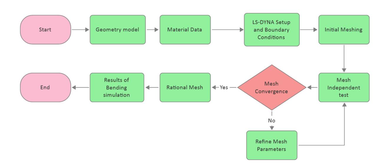
Figure 2 Flowchart of a typical simulation setup with mesh independent tests.
\[\bar{\sigma} = \sigma_y + A[1 - \exp(-B\varepsilon_{eq}^{pl})] \tag{1}\]
Table 2 Mechanical properties of SS400.
| Young's modulus [GPa] | Poisson's ratio | Density [kg.m-3] | Yield stress \([\sigma_y]\) [MPa] | A [MPa] | В |
|---|---|---|---|---|---|
| 213 | 0.3 | 7850 | 348 | 188.86 | 28.3293 |
Boundary conditions include a rigid fixed die, a rigid punch which moves downwardly at 10 mm/s and a sheet metal, which is set as symmetric to save computational time and resources. When the punch reaches the target position, it maintains the same position for one second before returning to the initial position with the same speed. The contacts between the die/punch and sheet metal have a friction coefficient of 0.1, which is used to prevent the sheet from sliding off.
For enhanced numerical accuracy in simulations of bending processes, one-way surface-to-surface contact is recommended within the LS-DYNA environment (ANSYS, n.d.). This contact formulation is particularly well-suited for sheet metal bending, where interaction occurs between a deformable sheet (defined as the slave surface) and a rigid tool, such as a punch or die (defined as the master surface). Forming contact, a specialized type of one-way contact, offers several advantages over standard contact definitions. Complex tool geometries are automatically handled, ensuring reliable contact detection. Furthermore, the sheet's motion relative to the tool is tracked, enabling adaptive remeshing. This adaptive remeshing is crucial for preserving mesh quality and obtaining accurate results by capturing intricate deformation details. Unrealistic penetrations between the sheet and the tool are mitigated through the application of penalty forces. Consequently, forming one-way contact is recognized as a valuable tool within LS-DYNA for achieving effective and precise simulations of metal forming processes.
To enhance convergence of the nonlinear equilibrium iteration process, artificial stabilization is employed (Maker & Zhu, 2001). Virtual springs are incorporated into the model to mitigate springback and improve numerical conditioning. These springs are progressively removed as the analysis approaches the termination time and are fully removed upon reaching the termination time. The selection of penalty stiffness for artificial stabilization is a critical parameter. There are different values for artificial stabilization that have been categorized (Maker & Zhu, 2001) and evaluated (Z. Lin et al., 2000). A value of 0.01 is selected, as it gives the largest springback displacement, exhibiting closer agreement with experimental results. The artificial stabilization is activated after the punch starts to retract until reaching the termination time.
The initial mesh size, as recommended by ANSYS, is used as a starting point. Following the initial simulation run, regions exhibiting the highest deformation or deformation gradients are refined with a finer mesh. Conversely, regions with minimal deformation are meshed more coarsely. This approach allows for the efficient use of computational resources and processing time. In this study, block-structured mesh is employed for spatial discretization of the solution domain. This mesh type is advantageous due to its efficient use of memory, improved computational performance, simplified numerical formulation, and reduced number of cells (Sauer & Morsbach, 2023). Figure 3 illustrates the process of creating a block-structured mesh for the sheet metal component. The geometry of the sheet metal is first divided into several blocks in Figure 3a, which are then meshed with hexahedral elements in Figure 3b. This approach allows for better control over mesh quality and improved computational efficiency.
- a. Partitioning of the sheet metal into regions b. Resulting mesh
Block-structured mesh generation.
Post-processing of numerical data
The bending results, including node coordinates measured using LS-PrePost, are shown in Figure 4. The coordinates of four nodes at each line in Figure 4 are taken from the outermost layer of the bent sheet metal, two nodes from the left outer layer and right outer layer. The bent angle is calculated based on the lines connecting the corresponding pairs of nodes on each side of the outer layer along the bend curvature. The average of nine angles from nine curvatures is taken as the bent angle.
Bent angle measurement.
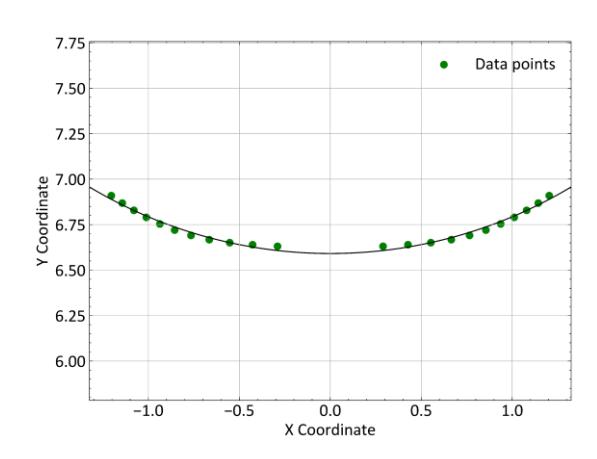
The bent radius is determined by extracting the node coordinates at the middle cross-section layer, as illustrated in Figure 5((a)). These node coordinates are carefully selected to represent the outermost layer of the bent sheet metal. To accurately capture the curvature, the extracted nodes are connected using an in-house code, which fits a smooth curve through the data points, as shown in Figure 5((b)). The bent radius is then measured directly from this fitted curvature.
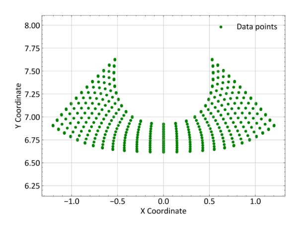
- (a) Nodal coordinates at the middle cross-sectional layer
- (b) Fitting the outermost layer for measuring the bent radius.
Bent radius measurement.
Results
Mesh Independent Test
The simulations are performed on an HP Z6 G4 workstation. This workstation is equipped with an Intel Xeon Gold 6146 processor (3.2 GHz, single CPU configuration with twelve cores), 128GB RAM, and a 512GB SSD. Each simulation utilized all twelve cores, completing in approximately 1 hour and 43 minutes for the case of nearly 400,000 nodes. The mesh independence test, shown in Figure 6, is carried out using meshes ranging from 120,000 to 470,000 nodes to determine a rational balance between accuracy and efficiency. The trends in bent angle, bent radius, and computational time exhibit monotonic behavior; as the mesh is refined, the bent angle and bent radius decrease slightly, while the computational time increases significantly.
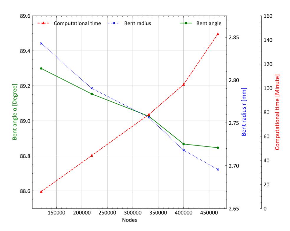
Mesh independent test.
Initially, with a 120,000-node mesh, the highest values for the bent angle and bent radius are observed, while the computational time is the smallest. As the mesh increases to 220,000 nodes, the bent angle decreases slightly from 89.29 degrees to 89.15 degrees, and the bent radius reduces from 2.84 mm to 2.79 mm. At 330,000 nodes, a more rapid reduction is observed, with the bent angle decreasing to 89.02 degrees and the bent radius to 2.75 mm, while the computational time continues to increase linearly. When the mesh is further refined to 400,000 nodes, the changes in bent angle and bent radius become more pronounced, reducing to 88.86 degrees and 2.71 mm, respectively. Beyond this point, from 400,000 to 470,000 nodes, only slight variations are noted—an increase of approximately 0.02% in the bent angle (to 88.84 degrees) and a 0.83% decrease in the bent radius (to 2.69 mm). However, the computational time increases by nearly 30%. Compared to the 400,000-node mesh, the finest mesh of 470,000 nodes slightly improves accuracy; however, it significantly increases computational time. The 400,000-node mesh is therefore selected as it provides a reasonable compromise between accuracy and efficiency. Upon completion of the simulation, the deformation results are analyzed using LS-PrePost, which includes an integrated tool for measuring both the bent angle and the bent radius.
Figure 7 is interpreted to show the final deformation of a sheet metal that has been subjected to a V-bending process with a V-groover. It is observed that plastic deformation has been governed by the motion of dislocations, which are defects within the crystal lattice. Dislocation theory and the concept of slip systems (Callister & Rethwisch, 2013) are used to explain the behavior seen in Figure 7((a)), and it is assumed that when the metal is deformed, dislocations are generated and move along specific crystallographic planes—slip planes—and in preferred directions—slip directions. These slip systems are characterized by the highest atomic packing, which provides the least resistance to dislocation motion. In Figure 7((b)), regions of pronounced deformation are seen where dislocation motion is believed to have been most active. It is suggested that under applied stress, dislocations are moved along the most favorably oriented slip systems, thereby allowing the material to flow and accommodate the imposed shape change. The unusual deformation observed at the outer surface of the sheet metal is thought to be caused by a local alignment of the slip systems with the direction of the applied force, resulting in enhanced slip and material flow along paths where the resolved shear stress is greatest. It is assumed that the V-groover played a significant role in directing this movement by concentrating on the stress in certain regions, which in turn promoted dislocation activity along those preferred slip directions.
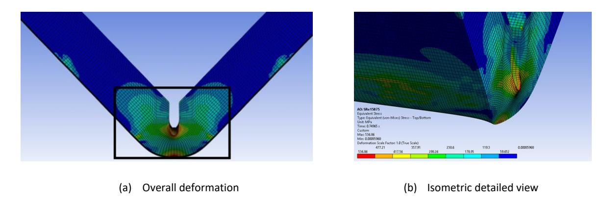
Final deformation of sheet metal under the V-bending process.
Verification of Energy Evolution
In the previous work (Le et al., 2025), our numerical model was validated by comparison with experimental and numerical results without the V-groove available in Vuong et al.'s study (Vuong et al., 2020). In the present study, the evolution of different energy components over time during the simulation is shown in Figure 8. Time (s) is shown on the x-axis, while energy () is displayed on the y-axis. Several key observations can be made based on the results. At the beginning, the internal energy is recorded at zero. Within the first 0.1s, it increases rapidly and stabilizes at approximately 1900 () remaining constant throughout the rest of the simulation. This trend indicates that most of the applied work is absorbed as internal energy, which is expected in a quasi-static deformation process.

Energy summary of simulation results.
The kinetic energy remains at an extremely low level for the entire duration of the simulation. This suggests that the process is governed by slow deformation rather than dynamic motion. As a result, accuracy in static structural analysis is maintained. The hourglass energy increases slightly and remains at a low value throughout the simulation. Since hourglass energy is significantly lower than internal energy, it indicates that numerical stabilization techniques effectively suppress non-physical deformations. In finite element analysis, hourglass energy should be kept significantly lower than internal energy to ensure accurate and reliable results (Livermore Software Technology Corporation (LSTC), n.d.). In this simulation, this condition is met, confirming the validity of the numerical model. The contact energy gradually increases and stabilizes around 225 () before experiencing a slight drop near 0.6 s. This behavior indicates that stable contact interactions are maintained during most of the deformation. However, minor separation or adjustments in contact conditions may occur later in the process. The dominance of internal energy and the minimal presence of kinetic energy confirm that the process is well-controlled and primarily involves plastic deformation. Low hourglass energy ensures numerical stability, while the trend in contact energy suggests proper interaction between contacting surfaces. These energy distributions validate the reliability of the simulation results in analyzing deformation behavior.
Influence of corner radius
The corner radius of the V-groover, as shown in Figure 9, significantly influences the bent angle and bent radius. Initially, at = 0.3969 mm, the highest bent angle of 88.86 degrees and a bent radius of 2.71 mm are observed. When the corner radius increases to 0.7938 mm, the bent angle and bent radius decrease by approximately 0.60% and 14.9%, respectively. A further increase to 1.1906 mm results in a continued decline, with reductions of 0.264% in the bent angle and 6.39% in the bent radius. However, as increases from 1.1906 mm to 1.5875 mm, both the bent angle and bent radius remain nearly unchanged, stabilizing at 88.09 degrees and 2.16 mm, respectively. Overall, comparing the smallest and largest corner radii, the bent angle decreases by 0.87%, while the bent radius is reduced by 20.34%.
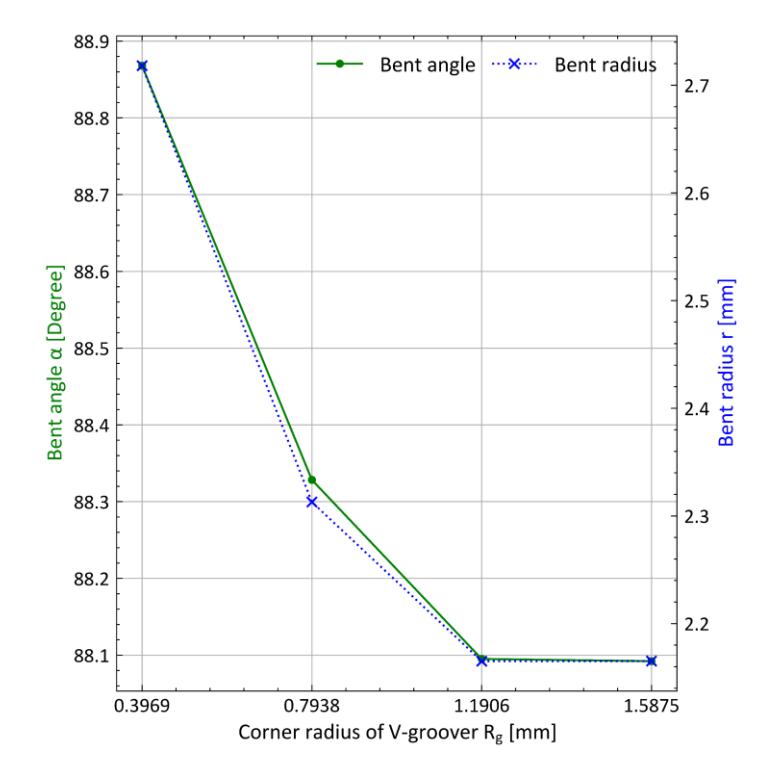
Influence of corner radius.
Springback behavior in bending is primarily influenced by two factors: the material's stress-strain response and the redistribution of internal forces during deformation material flow and redistribution during bending. During bending, the outer layer of the metal undergoes tensile stress and elongation, while the inner layer experiences compression. This stress distribution affects the final shape due to residual elastic recovery. As the corner radius of the V-groover increases, more material is removed at the bending region, reducing bending resistance. Consequently, both the bent angle and bent radius decrease as less force is needed to form the sheet metal.
Influence of insert's shape with the same cutting depth
In the previous section, the effect of the corner radius of a square insert ( = 90 degrees) on the bending process is examined. In this section, the influence of the insert's angle (as shown in Figure 10) is analyzed while maintaining a fixed cutting depth of / = 40%. The variation in the V-groover angle introduces different bending characteristics, which are discussed in terms of the bent angle and the bent radius .
The relationship between the bent angle and the V-groover angle follows a decreasing trend. As increases from 55 degrees to 80 degrees, the bent angle gradually reduces, reaching its minimum value at = 80 degrees. Beyond this point, a slight increase in is observed as further increases to 90 degrees. Compared to its initial value at = 55 degrees, the bent angle decreases by approximately 1.1% at its lowest point. This suggests that a larger generally results in a smaller bent angle, though the reduction is not substantial.
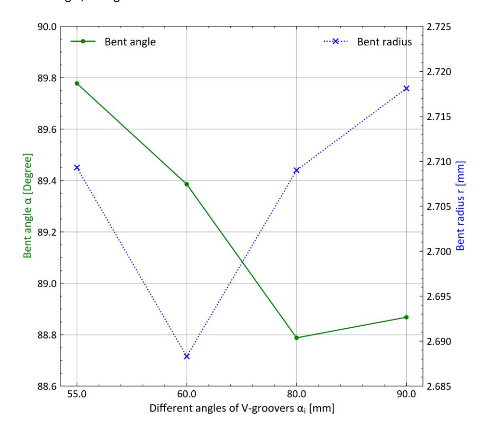
Influence of insert's shape with the same cutting depth.
The variation in the bent radius exhibits a different pattern. Initially, as increases from 55 degrees to 60 degrees, decreases to its minimum value. However, when continues to increase beyond 60 degrees, the trend reverses, and starts to increase. The largest variation in across the examined range of is approximately 1.09%, indicating a relatively minor overall change. This suggests that while the insert's shape influences the bent radius, the magnitude of this influence remains limited. Overall, the results indicate that the V-groover angle plays a role in shaping the final bent angle and bent radius. However, the total variations in both parameters remain small, implying that the insert's shape alone does not cause drastic changes in the bending process. Instead, the choice of may be used as a fine-tuning parameter to achieve precise bending outcomes. Nonetheless, other factors, such as material properties and process conditions, are likely to have a more significant impact on the final shape of the bent sheet.
Influence of insert's shape with the same cutting cross-sectional area
Figure 11 illustrates the effect of the insert's shape on the bent angle and bent radius while maintaining a constant cutting cross-sectional area. This contrasts with the previous section's analysis where the cutting depth is held constant. To achieve the same cutting area as the 60-degree triangular insert with a cutting depth of 0.8 mm, different depths are required: 0.815 mm for the 55-degree insert, 0.737 mm for the 80-degree insert, and 0.703 mm for the 90-degree insert.
As shown in the Figure 11, the final bent angle is found to be fairly consistent, showing minimal variation as the Vgroover angle is changed. The bent angle increases slightly from 89.0 degrees at a 55 degrees V-groover angle to a peak of nearly 89.9 degrees at 80 degrees, before decreasing to 88.7 degrees at the 90 degrees angle. This very small range of changes indicates that the final bent angle is not significantly affected by the V-groover angle. In contrast, the final
bent radius is highly dependent on the V-groover angle. As the V-groover angle is increased, the bent radius steadily increases. The smallest bent radius is approximately 2.6 mm at the 55 degrees V-groover angle. The radius then increases to 2.7 mm at 60 degrees, 3.2 mm at 80 degrees, and finally about 3.37 mm at the 90 degrees angle. This clear trend shows that a wider V-groover angle results in a larger bent radius.
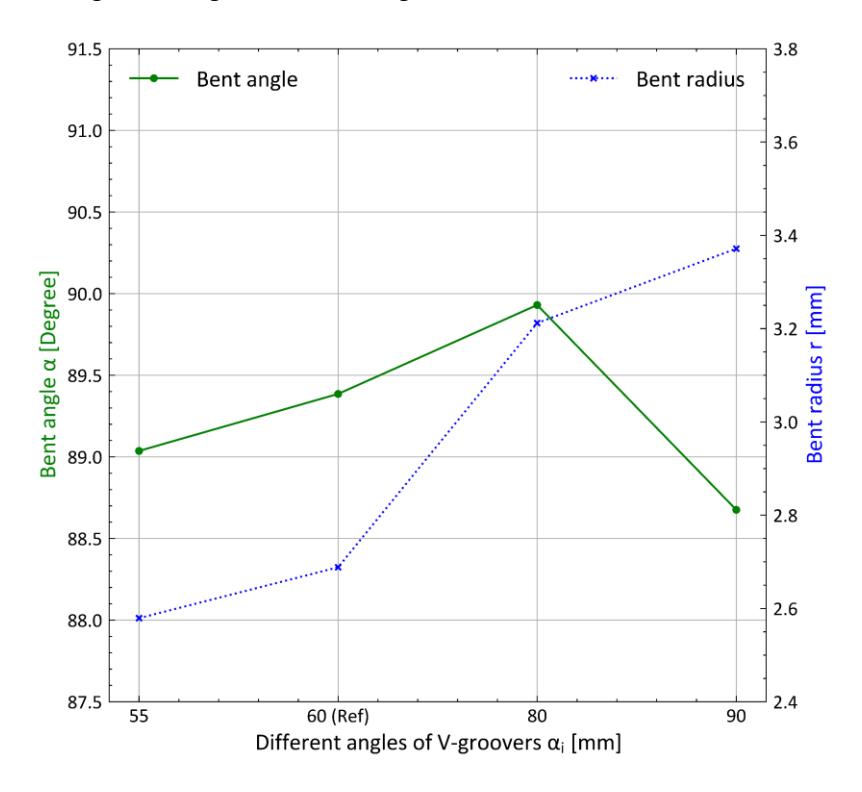
Influence of insert's shape with same cutting cross-sectional area.
Discussion
A larger corner radius of the V-grooving inserts consistently leads to a lower springback, as detailed in Influence of corner radius . This outcome can be interpreted as a direct result of the localized material removal, which effectively reduces the sheet metal's bending resistance in the deformation zone. By reducing the overall resistance, the sheet is easier to deform plastically, leading to a smaller elastic recovery after the punch is unloaded. This finding aligns with the general principle that localized weakening can enhance formability and reduce springback. Our results expand on this by specifically quantifying the effect of a geometric feature, which is the corner radius, on this phenomenon. The optimal choice in this case is the 90-degree insert with a 1.1906 mm radius, as it yielded the lowest springback and the tightest bend.
When the cutting depth is held constant, as shown in Influence of insert'sshape with the same cutting depth, minimal changes in the bending results are seen due to differences in the overall insert shape. This suggests that a more dominant factor in the bending outcome is the total volume of removed material, or more specifically, the crosssectional area of the groove, rather than the subtle changes in shape. This implies that, for a given depth, designers may have some flexibility in choosing the specific insert profile for different applications, as long as the material removal remains consistent, without drastically altering the bending performance. In this case, the 60-degree insert is optimal for achieving the minimum bent radius, while the 80-degree insert is the best choice for achieving the minimum bent angle.
A key finding, as detailed in Influence of insert's shape with the same cutting cross-sectional area, is the significant influence of the groove angle when the cutting cross-sectional area is kept constant. The bent angle shows minimal variation, staying consistently around 1.8 degrees. This indicates that the final bent angle is largely independent of the specific V-groover geometry. In contrast, the bent radius is highly sensitive to the V-groover angle, with the minimum
value of 2.57 mm which is achieved by the 55-degree insert. The optimal choice for achieving the minimum bent angle is the 90-degree insert.
The results confirm that V-groove geometry plays an important role in controlling bending and springback. Therefore, insert selection should be considered a key parameter in sheet metal forming processes. However, because each test case uses different boundary conditions (such as a constant corner radius, a constant cutting depth, and a constant cutting cross-sectional area), it is difficult to name one single best insert. Instead, the findings show that the most effective insert depends on the specific goal of the bending process. For example, 90-degree insert with a 1.1906 mm radius is best for achieving the tightest bend and lowest springback when the radius is constant. On the other hand, the 60-degree insert is the best choice for getting the smallest bent radius when the cutting depth is kept the same.
It is important to acknowledge that this study is conducted using finite element analysis. While the numerical model is validated in our previous work, experimental validation of these specific novel geometries would provide further empirical confirmation. The analysis is also performed for a specific material and under particular conditions; the applicability of these optimal geometries to other materials and forming processes may need further exploration. Future research could investigate the combined effects of V-groover geometry with other process parameters and material properties.
Conclusion
In this study, the influence of V-grooving inserts on the V-bending process is investigated using finite element analysis within the ANSYS LS-DYNA software environment. The focus is on analyzing the impact of different V-groover geometries on the final bent angle and bent radius of the sheet metal part, aiming to minimize springback and achieve small bending results.
This study finds that the corner radius of the V-groover has a significant effect on both the bent angle and bent radius. Increasing the corner radius leads to a decrease in both parameters, primarily due to the reduction in bending resistance caused by the removal of more material at the bending region. The shape of the V-groover insert also influences the bending outcome, with different geometries resulting in variations in both the bent angle and bent radius. When maintaining a constant cutting depth, the bent angle decreases with an increasing V-groover angle, while the bent radius achieves its minimum value at a V-groover angle of 60 degrees. When maintaining a constant cutting cross-sectional area, the bent angle increases as the V-groover angle increases to 80 degrees, while the bent radius increases steadily across all tested angles, highlighting the importance of the V-groover angle in controlling the final radius.
These findings have potential applications in optimizing the V-bending process for improved accuracy and control over the final part geometry. Future work could involve experimental validation of the simulation results and further exploration of the influence of other process parameters, such as sheet thickness and material properties, on the bending outcome.
Nomenclature
= Depth of V-groover
= Length
= Corner radius of V-groover
= Punch tip radius
= Die shoulder radius = Bent radius after springback
= Shoulder width = Sheet thickness / = Relative groove depth
= Width
= Bent angle after springback
= Angle of die = Angle of V-groover ℎ = Angle of punch
Acknowledgment
We acknowledge Ho Chi Minh City University of Technology (HCMUT), VNU-HCM for supporting this study.
Compliance with ethics guidelines
The authors declare they have no conflict of interest or financial conflicts to disclose.
This article contains no studies with human or animal subjects performed by authors.