
Introduction
During tunnel construction through fractured and weak rock strata, significant face extrusion deformations may occur owing to excavation-induced disturbances. In extreme cases, these deformations may lead to face collapse or instability, severely compromising the safety of tunnel construction (Song et al. 2022 and LUNARDI P, 2008). Compared with the New Austrian Tunneling Method (NATM), the New Austrian Method places greater emphasis on "active support," leveraging the face-advanced core soil system to control tunnel deformation. This approach demonstrates significant advantages in managing surrounding rock deformations within fractured soft rock formations (Song et al. 2020 and Zhang er al. 2008).
Fiberglass anchor bolts, commonly used to reinforce the advanced core soil system, possess high tensile strength but low shear strength, rendering them prone to rupture but suitable for mechanized construction. Mei and Chen (2008) analyzed the strengthening effect of fiberglass anchor bolts on the "to-be-excavated core body" and demonstrated through numerical simulations that fiberglass anchor bolts can effectively control tunnel deformation. Tan et al. (2017) performed a comparative analysis between numerical simulations and field monitoring data of the Yezhu Mountain Tunnel. Using the results, the authors defined the general range of surface settlement and excavation space effects and provided recommendations for the optimal lap length of anchor bolts in tunnel construction. Wang et al. (2017), performed numerical simulations considering the Yezhu Mountain Tunnel project to investigate the influence of different excavation and reinforcement methods on face deformation and predict the variation in longitudinal settlement along the tunnel crown. Considering the Meiyu Expressway Qishan Tunnel project as an example, Ye et al. (2017) used a sliding micrometer to measure the variation in tunnel extrusion displacement and conducted numerical experiments using finite difference methods to study the deformation characteristics of tunnel extrusion displacement under weak surrounding rock conditions. The authors established a relationship between the length of the fractured
1CSCEC International. Suzhou High-tech Zone 215163, China
2China Construction Third Engineering Bureau Group Co., Ltd. Wuhan Wuchang District 430073, China
3China Construction Seventh Engineering Division Corp., Ltd. Zhengzhou Economic Development Zone 450048, China
School of Civil Engineering, Xi'an University of Architecture and Technology, Xi 'an Beilin District 710055, China 6 Shaanxi Key Laboratory of Geotechnical and Underground Space Engineering, Xi 'an Beilin District 710055, China
zone and stiffness ratio of soft to hard rock. Cui et al. (2015) performed numerical simulations to analyze the suppression effects of face anchor reinforcement parameters on surrounding rock deformation and proposed methods for determining the anchor bolt length based on pre-convergence deformation and lap length considering the face rupture depth. Numerous scholars, including Peila et al. (1994), have examined the reinforcement effects and mechanisms of face anchor bolts, comparing the effects of parameters such as reinforcement length, density, and anchor stiffness on surrounding rock deformation control. The results indicate that face anchor bolts can enhance the strength and stiffness of the advanced core soil, reducing the stress loss caused by excavation and improving the stability of the tunnel face, thereby effectively controlling extrusion deformations and surface settlement.
Notably, the existing studies have predominantly focused on the isolated reinforcement effects of face anchor bolts, with limited comparative analyses of different support types within the NATM framework. Consequently, this study examines Tunnel No. 2 of a specific expressway and conducts numerical simulations of two support types within the NATM framework. The surrounding rock deformation and stress distribution under both conditions are compared to demonstrate the reinforcing effect of face anchor bolts in fractured soft rock strata.
Methods
Overview of tunnel engineering and support scheme
Project overview
The project section assessed in this study spans approximately 13 km, with an elevation ranging from 204.8 m to 300.0 m. According to project documentation, the tunnel is primarily excavated through the PzGr rock formation, characterized by significant weathering and fracturing. The geological profile along the tunnel alignment is shown in Figure 1.
Geological profile along the tunnel alignment.
The PzGr strata are primarily composed of granite, ranging from lightly to highly weathered and from large-scale fracturing to severe fragmentation. Within the PzGr formation, the intrusive and metamorphic units include pale gray granite, metamorphic granite, and granite diorite, ranging from lightly to highly weathered. The outcrop ranges from extensive to severely fractured.
Types of tunnel support
The NATM advocates full-face excavation under all geological conditions. To address the various engineering challenges that may arise during tunnel construction, such as fractured zones, water ingress, and uneven pressure, NATM proposes four types of support systems—B0, B0V, B2V, and B1—tailored to specific conditions. Details of these support types are shown in Figure 2.
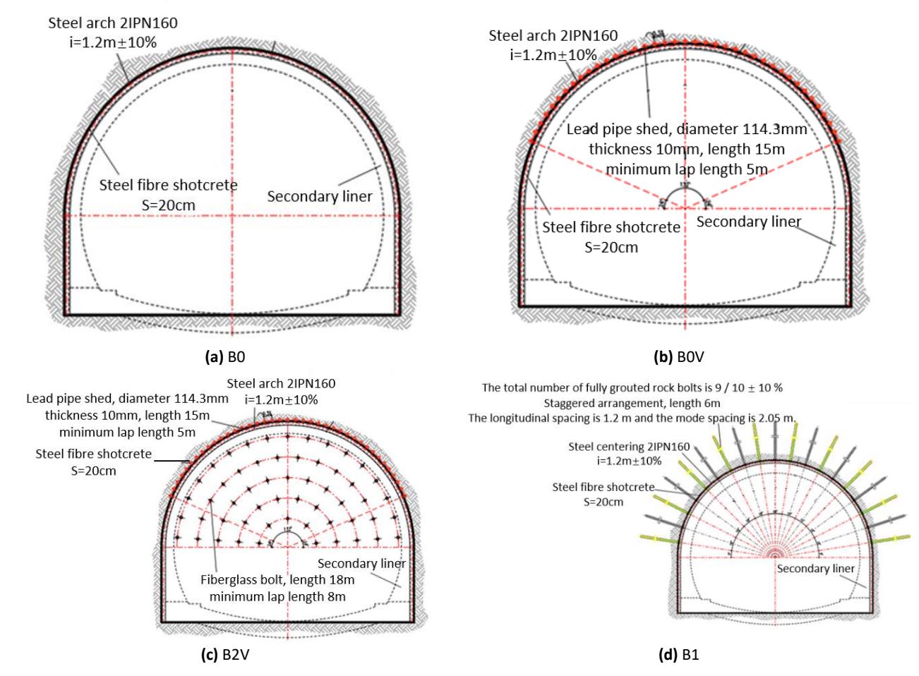
Profiles of tunnel supports in the NATM.
Table 1 Section support measures and applicable conditions.
| Profile type | Support and construction sequence | Tuning parameter | Application |
|---|---|---|---|
| B0 | Drainage pipe + 2.4 m footage + full section + initial support + bottom + secondary lining | Spacing of steel arch | General to poor rock mass, moderate to high fracture, short-term stability |
| B0V | Drainage pipe + advanced pipe shed + 1.0 m footage + full section + initial support + bottom + secondary lining | Number of pipe sheds | Shallow burial, bias, tunnel entrance, highly fractured, strong water gushing, and proximity to fault zones |
| B2V | Drainage pipe + advanced pipe shed + core soil reinforcement + 1.0 m footage + full section + initial support + bottom + secondary lining | Numbers of pipe sheds and glass anchors | When the shallow buried or fracture conditions, has been used in advance large pipe roof pre support but the stability of the tunnel face cannot be ensured |
| B1 | Drainage pipe + 2.8 m footage + full section + bolt + initial support + bottom + secondary lining | Number of anchors | Medium to poor rock mass. Bolts are used to stabilize large blocks of rock, usually near the fault zone |
Table 2 lists the convergence thresholds corresponding to different tunnel support types. When the deformation exceeds the alert threshold, stronger support measures should be implemented according to the support type to control the deformation within the alarm threshold. If higher-strength support measures still result in deformation exceeding the alarm threshold, a support type with even greater strength should be selected to restrict further deformation and ensure the safety and stability of the tunnel.
| Support type | Terms of reference | Mean value | Attention threshold | Alarm threshold |
|---|---|---|---|---|
| B0 | 20.0–25.0 | 22.5 | 40.0 | 60.0 |
| B1 | 20.0–25.0 | 22.5 | 40.0 | 60.0 |
| B0V | 20.0–25.0 | 22.5 | 50.0 | 80.0 |
| B2V | 20.0–25.0 | 22.5 | 60.0 | 80.0 |
Table 2 Convergence thresholds for different tunnel support types (mm).
According to engineering design data, the stability of the tunnel face within the section from K3+605 to K3+675 corresponds to a Class B cross-section. If advanced support to reinforce the core soil is not implemented in a timely manner during construction, the tunnel face would be highly susceptible to instability and collapse. Thus, the B2V support type was selected for construction.
Numerical simulation and calculation parameters
Numerical simulation software was used to model Tunnel No. 2. The B2V support type was implemented in the simulation, while the B0V support type was used as a control group to compare and analyze the effect of face anchor bolts on the deformation and stress control of the surrounding rock.
Numerical analysis model
A numerical model was developed based on the cross-sectional dimensions of the tunnel of interest. Considering the errors introduced by boundary effects and computational efficiency, the model dimensions were set as 91 m × 70 m × 101 m, with a tunnel diameter of 11.56 m. The tunnel was located 39 m from the left, right, and lower boundaries. The three-dimensional numerical model of the tunnel is shown in Figure 3.
3D model of the tunnel
To evaluate the control effect of the B2V support type on surrounding rock deformation, numerical simulations were conducted for both the B2V and B0V support types, with the latter serving as the control group for comparative analysis. The three-dimensional numerical models of the two schemes are shown in Figure 4. To comprehensively analyze the deformation and stress conditions at different tunnel locations, four cross-sections at distances of 5 m, 20 m, 35 m, and 50 m from the tunnel entrance were designated as Feature Sections 1, 2, 3, and 4, respectively.
Figure 4 Schematic of 3D numerical model.
Parameter calculation
The tunnel lining was simulated using beam elements for the canopy and cable elements for the anchor bolts. The grouting reinforcement zone around the canopy was modeled by increasing the values of the physical and mechanical parameters of the surrounding rock. The material parameters for each model element are provided in Table 3. According to the design documentation, tunnel excavation was performed using the B2V support type, with an advanced canopy installed within a \(66^{\circ}\) range from the tunnel crown centerline. The canopy had a length of 15 m, an overlap length of 5 m, spacing of 0.38 m, thickness of 10 mm, and a horizontal angle of 5°. The face anchor bolts were simulated using cable elements, with a length of 18 m, overlap of 8 m, cross-sectional area of \(1.57 \times 10^{-3}\) m², elastic modulus of 45 GPa, tensile strength of 500 MPa, grouting stiffness of 17.5 MPa, and grouting cohesion of 200 kPa. A total of 121 anchor bolts were installed, with a reinforcement density of 0.92 bolts/m². The initial support consisted of a steel arch and shotcrete C25 steel fiber-reinforced concrete, while the secondary lining was reinforced with 90-cm-thick C35 concrete.
| Material | Volumetric weight \(\gamma\) (kN/m\(^3\)) | Elastic modulus E (GPa) | Poisson ratio v | Cohesion c (kPa) | Angle of internal friction \(\boldsymbol{\varphi}\) (o) | Thickness d (m) |
|---|---|---|---|---|---|---|
| Rock-soil mass | 25 | 1.0 | 0.3 | 80 | 22 | - |
| Grouting area | 25 | 1.9 | 0.23 | 150 | 24 | 0.7 |
| Fracture zone | 25 | 0.7 | 0.3 | 40 | 20 | - |
| Primary support | 25 | 30 | 0.20 | - | - | 0.2 |
| Pipe roof | 78.5 | 210 | 0.35 | - | - | - |
Table 3 Parameters of surrounding rock and supporting structure.
Results
Extrusion deformation analysis of tunnel face
The extrusion deformation of the tunnel face at the Y = 35 m cross-section under both support schemes is shown in Figure 5. The maximum extrusion deformation for the B0V support type is approximately 128.66 mm. The corresponding value for the B2V support type is approximately 41.36 mm, representing a 69.7% compared with B0V. Additionally, the location at which pre-convergence deformation occurs in the B2V case is farther, demonstrating that face anchor bolts can effectively control the extrusion deformation of the tunnel face and delay the onset of pre-convergence deformation.
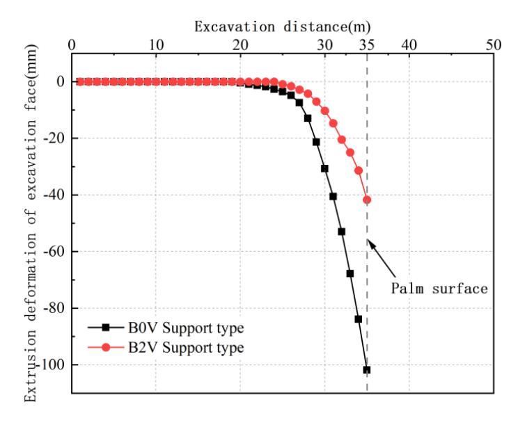
Comparison of extrusion deformation of tunnel face.
To illustrate the influence of face anchor bolts on extrusion deformation at the tunnel face, the deformation contour plots for the B0V and B2V support types at the Y = 35 m cross-section are shown in Figures 6 and 7, respectively. In terms of the lateral deformation distribution, the extrusion deformation contour for the B2V case is more evenly distributed, characterized by a flatter shape, with deformation decreasing gradually from the center outward and exhibiting a more distinct transition zone. In contrast, the B0V case exhibits a more concentrated contour distribution with a circular shape and more localized transition zone. In terms of the longitudinal deformation distribution, varying degrees of deformation are observed in the advanced core soil. Under the B2V condition, the deformation distribution is more uniform, indicating that the combined use of an advanced canopy and face anchor bolts can effectively control the extrusion deformation of the advanced core soil.
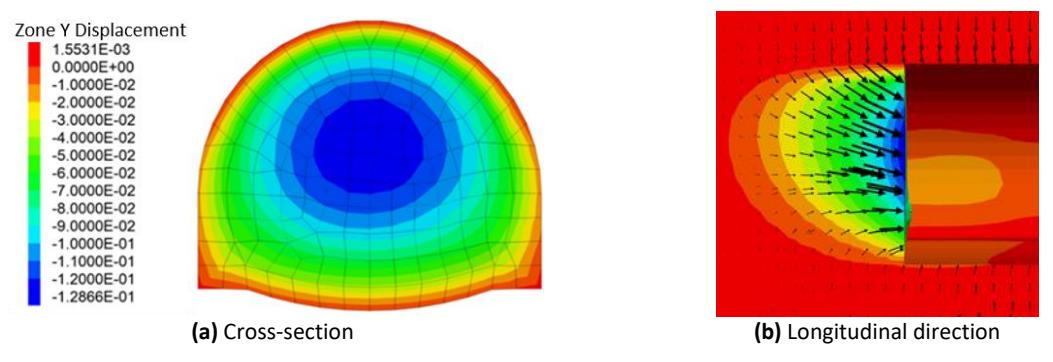
Cloud image of palm face deformation with the B0V support.
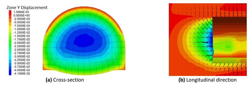
Cloud image of palm face deformation with the B2V support.
Tunnel vault settlement deformation
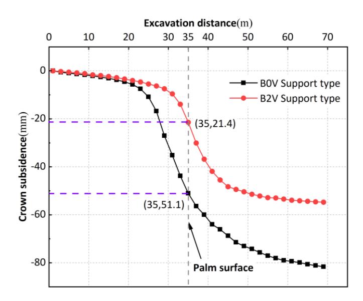
To analyze the settlement deformation behavior of the tunnel crown under the two support schemes, numerical simulation results for the tunnel crown settlement at the Y = 35 m cross-section are presented in Figure 8.
The crown settlement under both support types follows a slow deformation–rapid deformation–stable deformation trend. In the region ahead of the tunnel face, pre-convergence deformation occurs within a certain range in the surrounding rock owing to the spatial effect of the excavation face (primarily consisting of small elastic deformations), corresponding to the slow deformation phase. As excavation progresses toward the analysis section, the supporting force from the excavated rock mass is lost, causing the surrounding rock at the section to transition from a threedimensional stress state to a two-dimensional stress state, resulting in a rapid increase in deformation. This stage marks the rapid deformation phase. As the tunnel face moves farther from the analysis section, the spatial effect of the face gradually diminishes, and the support structure increasingly bears the load of the surrounding rock, thus preventing further deformation and leading to stabilization, corresponding to the stable deformation phase.
Furthermore, the pre-convergence deformation at the tunnel crown differs between the two support schemes. For the B0V and B2V conditions, the pre-convergence deformation values are 51.1 mm and 21.4 mm, accounting for 62.6% and 39.2% of the total deformation, respectively. Thus, the B2V support type significantly reduces the contribution of preconvergence deformation to the total deformation by enhancing the strength of the advanced core soil, resulting in better control over deformation and support installation during tunnel construction.
Contrast map of vault settlement.
Based on numerical simulation results, the surrounding rock deformation values at various locations of each crosssection and proportion of pre-convergence deformation in the total deformation are summarized in Tables 4.
The total deformation at various locations across the four cross-sections under the B2V condition is significantly smaller than that under the B0V condition. Section 3, which crosses a fractured zone, exhibits the highest deformation. On average, the total deformation values at all positions in the four cross-sections under the B2V support type are 26.2% lower than those under the B0V support type.
In terms of the proportion of pre-convergence deformation, the average value for the B0V support type is 48.4%. The corresponding value for the B2V support type is 31.5%, representing a significant reduction in pre-convergence deformation. Additionally, the B2V support type, reinforced with face anchor bolts, significantly reduces the degree of extrusion deformation at the tunnel face. Specifically, the deformation at Sections 1, 2, 3, and 4 is reduced by 65.2%, 65.9%, 67.9%, and 66.1%, respectively, compared with those for the B0V support type.
These results demonstrate that the B2V support type effectively controls the surrounding rock deformation within the alarm threshold, rendering it more suitable for strata with poor rock quality and high fragmentation, providing enhanced deformation control.
| Location | Support type | Section | Pre-convergence deformation | Convergence deformation | Total deformation | Proportion of pre convergence deformation (%) |
|---|---|---|---|---|---|---|
| B0V | 1 | 21.70 | 34.67 | 56.37 | 38.5 | |
| 2 | 27.99 | 31.18 | 59.17 | 47.3 | ||
| 3 | 51.10 | 30.53 | 81.63 | 62.6 | ||
| 4 | 29.32 | 34.28 | 63.60 | 46.1 | ||
| Crown subsidence | 1 | 10.76 | 35.72 | 46.48 | 23.2 | |
| 2 | 14.53 | 33.19 | 47.72 | 30.5 | ||
| B2V | 3 | 21.43 | 33.24 | 54.67 | 39.2 | |
| 4 | 15.58 | 33.00 | 48.58 | 32.1 | ||
| B0V | 1 | 57.51 | ||||
| 2 | 62.24 | |||||
| 3 | 128.66 | |||||
| Extrusion | 4 | 78.72 | ||||
| deformation of | B2V | 1 | 20.01 | |||
| excavation face | 2 | 21.20 | ||||
| 3 | 41.36 | |||||
| 4 | 26.66 | |||||
Table 4 Deformation statistics for each section type of the two supporting types (mm).
Stress analysis of surrounding rock at tunnel face
Figures 9 and 10 illustrate the changes in the minimum and maximum principal stresses at the Y = 35 m cross-section for both support types. Figure 9 shows that the minimum principal stress at the tunnel face for the B0V condition is nearly zero. This is attributable to the loss of the original support from the surrounding rock at the face owing to excavation, resulting in a dramatic loss of stress. The minimum principal stress near the tunnel face in the B0V condition is 1 kPa, whereas that under the B2V condition is 50 kPa. Thus, the use of face anchor bolts reduces the stress loss in the surrounding rock at the tunnel face, helping maintain the three-dimensional compressive stress state in the advanced core soil and enhancing the stability of the core soil at the tunnel face.
Face anchor bolts exert counterpressure on the advanced core soil, reducing stress loss caused by excavation and increasing the minimum principal stress in the surrounding rock at the face. Conversely, the advanced core soil applies a tensile force toward the tunnel interior on the anchor bolts, achieving a force equilibrium state. The relative friction between the anchor bolts and advanced core soil increases the longitudinal horizontal stress in the advanced core soil.
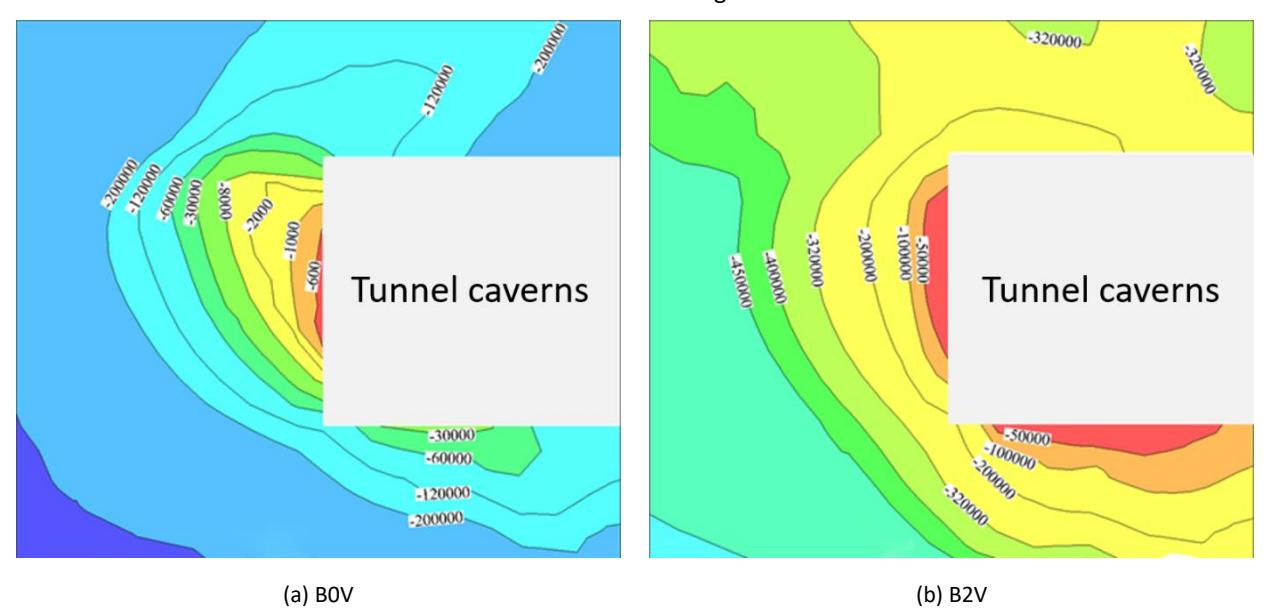
Isogram of minimum principal stress for the two support types.
Figure 10 shows the contour lines of the maximum principal stress for the B0V and B2V support types. As both support types incorporate advanced canopy support, a longitudinal arch effect is observed above the tunnel. However, the maximum principal stress at the tunnel face is higher in the B2V condition. Compared with the B0V condition, the B2V condition exhibits a more pronounced longitudinal arch principal stress curve with a broader influence range.
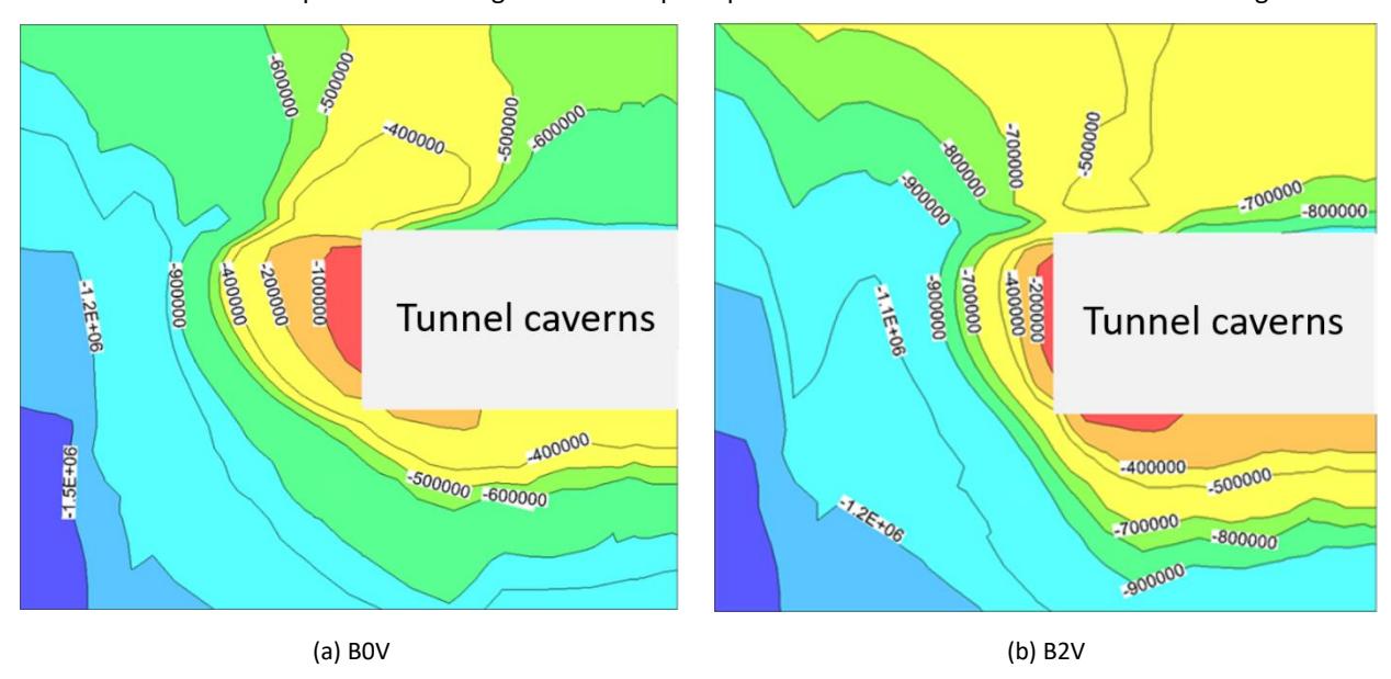
Maximum principal stress contour maps for the two support types.
These findings demonstrate that the B2V support type provides better control over face extrusion deformation, crown settlement, and stress loss, rendering it more suitable for strata with poor rock quality and high levels of fragmentation.
Discussion
Discussion of on-site monitoring results
The key parameters monitored on-site include the crown settlement deformation and tunnel clearance convergence. Crown settlement is measured using a total station (model TCR702, accuracy "1"), whereas clearance convergence is monitored using both a total station and convergence gauge (model TCR702/JSS30A30).
Four monitoring cross-sections are selected along the K3+605 to K3+675 section of the tunnel, corresponding to mileage markers K3+610, K3+625, K3+640, and K3+655. Monitoring data from these four cross-sections are compiled into the crown settlement monitoring curve shown in Figure 11(a), and the numerical simulation results are presented in Figure 11(b).
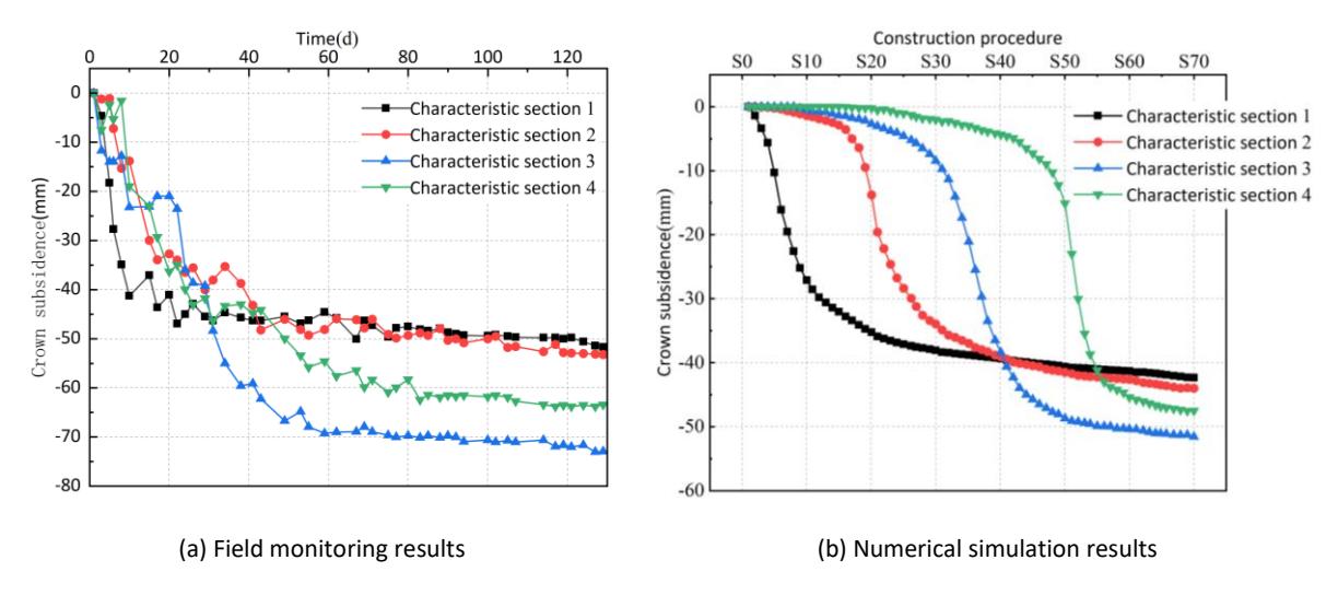
Time history curves for arch settlement, derived from monitoring and simulation data.
1. On-Site Monitoring Time-Series Curves
As shown in Figure 11(a), all four characteristic cross-sections exhibit the same deformation trend. Most of the convergence deformation occurs within the first 60 d, after which the surrounding rock deformation gradually stabilizes, following the rapid deformation–slow deformation–stable deformation pattern.
The deformation at characteristic cross-sections 1 and 2 is similar and significantly smaller than that at cross-sections 3 and 4. The deformation at all monitoring points of characteristic cross-section 3 is higher than those at other sections, likely because this cross-section is located within a fractured zone with poor rock quality. Additionally, characteristic cross-section 4 (Y = 50 m), situated at the end of the fractured zone (Y = 28–52 m), is also significantly influenced by the fractured zone, resulting in deformation that is second only to that of cross-section 3.
2. Comparison Between On-Site Monitoring and Numerical Simulation Results
Table 5 summarizes the on-site monitoring values and numerical simulation results of arch roof settlement at the crown position. The simulated values are consistently smaller than the on-site monitoring results. The most significant discrepancy occurs at characteristic cross-section 3, likely owing to the significant impact of the fractured zone at this location, contributing to increased deformation.
| Table 5 Comparison between field monitoring values and simulated values of arch roof settlement (mm) |
|---|
| Location of section | Field monitoring | Numerical simulation |
|---|---|---|
| Characteristic section 1 | 51.75 | 46.48 |
| Characteristic section 2 | 53.24 | 47.72 |
| Characteristic section 3 | 72.91 | 54.88 |
| Characteristic section 4 | 63.43 | 48.58 |
In the numerical simulation, the surrounding rock is assumed to be homogeneous and isotropic to simplify the calculations. However, in actual engineering, the rock mass is heterogeneous, anisotropic, and influenced by various factors such as construction disturbances and groundwater effects. These factors were not considered in the numerical simulation, resulting in a conservative estimate of the deformation. Nevertheless, numerical simulations remain a useful tool for predicting tunnel deformation. To ensure the tunnel safety and stability, the simulation results must be integrated with on-site monitoring data to perform a comprehensive analysis.
Conclusion
This study compares the B0V and B2V support types used in the NATM by analyzing the corresponding face extrusion deformation, crown settlement deformation, and surrounding rock stress at the tunnel face through numerical simulations. A comparison of on-site monitoring and numerical simulation results confirms the superior deformation control effect of the B2V support type. The following conclusions are derived:
The utilization of face anchor bolts demonstrates significant benefits in tunnel stability by substantially mitigating face extrusion deformation. Specifically, their application under the B2V support type reduces the maximum extrusion deformation by 69.7% compared to the B0V type. Moreover, the deformation distribution becomes more uniform, exhibiting a distinct transition zone, which contributes to a more controlled structural response.
Furthermore, face anchor bolts prove highly effective in controlling pre-convergence deformation. The data indicates a 58.1% reduction in this deformation compared to the B0V condition, accompanied by a 23.5% decrease in its proportion to the total deformation. This suppression of pre-convergence is critical, as it facilitates more manageable deformation control and simplifies the implementation of subsequent support during the construction process.
Most notably, the efficacy of this technique is particularly pronounced in fragmented strata with poor rock quality. Under the B2V condition, the tunnel face exhibits a significantly higher minimum principal stress and a more enhanced longitudinal arch effect. This improvement is attributed to the bolts reinforcing the advanced core soil, thereby increasing its longitudinal horizontal stress while reducing the stress in the deeper surrounding rock. Ultimately, this mechanism maintains a compressive three-dimensional stress state in the core soil, which is crucial for ensuring the overall stability of the surrounding rock.
Acknowledgments
We sincerely thank all individuals and institutions that have contributed to the success of this study. We appreciate the project team involved in the field monitoring of the tunnel, who provided valuable data that was essential to this study. Additionally, we thank the reviewers for their insightful feedback, which has greatly improved the quality of this paper.
Compliance with ethics guidelines
The authors declare they have no conflict of interest or financial conflicts to disclose.
This article contains no studies with human or animal subjects performed by the authors.