
Introduction
The global transition towards sustainable energy has made electrical motors a critical technology for future transportation. This trend clearly reflected in Indonesia's national strategy, which includes an ambitious target for netzero carbon emissions by the year 2060 and a program to deploy r two million electric cars and thirteen million electric motorcycles by 2030 (Agency, 2022). As these goals underscores, the performance and reliability of electric motors are now central to achieving a sustainable energy future. As the core component of an EV, the electric motor converts stored electrical energy into mechanical force, that propels the vehicle (Aishwarya & Brisilla, 2022). However, this energy conversion process is not perfectly efficient. Unavoidable losses from source such as friction, windage, and electromagnetic effects generate waste heat, which in turn leads to a significant rise in motor temperature (Chapman, 2012; Saidur, 2010). This temperature escalation often pushes the motor beyond its safe operating threshold, typically identified around 60°C (Previati et al., 2022; Putra & Ariantara, 2017) Operating an electric motor under such thermal stress not only impairs its immediate performance but also dramatically increases the risk of premature failure and permanent damage (Aprianingsih et al., 2018; Garniwa, 2019). A particularly concerning consequence is the irreversible demagnetization of the motor's magnetic core, which directly diminishes its long-term efficiency (Sun et al., 2020). Clearly, to ensure electric motors can operate reliably and optimally, an advanced and effective cooling system is not merely beneficial, but absolutely essential.
The imperative for robust thermal management in electric motors has spurred the development of diverse cooling strategies, broadly categorized into active and passive systems. Active cooling, encompassing methods such as forced air and liquid circulation, represents the more conventional approach (Gammaidoni et al., 2023). Air cooling is favored for its simplicity and cost-effectiveness (Lei et al., 2022). In contrast, liquid cooling stands out for its superior heat transfer coefficients, allowing for higher power densities within the motor (Tikadar et al., 2021; Zhang et al., 2024). I For example, Hyundai Group introduced a direct coolant spray method (Group, 2022), while (Deriszadeh & de Monte, 2021)
Laboratory of Nanoscience and Technology, Department of Mechanical Engineering Universitas Andalas Padang, Jalan Limau Manis, Padang 25163, West Sumatra, Indonesia
developed a nanofluid-enriched water cooling jacket. Other researchers have explored a more direct cooling method; for instance,(Davin et al., 2015; Sandip Garud & Lee, 2024), both studied techniques that spray oil directly onto stator coil.
Passive cooling strategies, have become major focus in thermal management, one of which the use of heat pipes, which is starting to attract attention from many researches. The device is highly effective because it can transfer significant amount of heat passively, which eliminates the need for mechanical pumps. (Chaudhry et al., 2012). As in electric motor applications, researches have explored various integration methods, ranging from placement within the motor casings (Hodowanec, 2009; Yang et al., 2024) or between windings and the housing (Sun et al., 2020). Other advanced configuration include the use of L-shaped heat pipes by researchers(Putra & Ariantara, 2017; Tetuko et al., 2019), pulsating heat pipes (PHP) by (Aprianingsih et al., 2018), and even hybrid systems, that combine heat pipes with active liquid cooling, which was tested by (Huang et al., 2019). Throughout this study, it can be concluded that the high effective thermal conductivity of heat pipes consistently makes them one of the most efficient solutions for motor cooling as demonstrated in foundational study by (Barua et al., 2013; Chaudhry et al., 2012; Hodowanec, 2009)
The Rotating Heat Pipe (RHP)has emerged as a highly promising solution for cooling rotating machinery (Du & Huang, 2022; Reding & Cao, 2017). Unlike a stationary heat pipe, an RHP rotates on its axis, generating a centrifugal force. This force drives the working fluid back from the condenser to the evaporator. As the result, heat transfer efficiency is significantly enhanced(Li & Liu, 2020; Luo et al., 2023; H. Wang et al., 2022; H. Wang et al., 2023). Many studies also have confirmed a clear trend, that the faster the RHP rotates, the lower its thermal resistance becomes (Denkena et al., 2021; Lian et al., 2016; Zhang, Chen, Jiang, & Xu, 2023).
The versatility of RHP has also been demonstrated in a wide range of rotary applications, from precision bone drills (Chen et al., 2022) to and heavy-duty grinding wheels (Qian et al., 2020; Zhang, Chen, Jiang, Xu, et al., 2023). Importantly, the electric motor shaft itself represents a source of heat , primarily due to friction the end bearings, with losses that intensify at higher speeds (X. Wang et al., 2022). To address this issue, recent investigations have begun exploring the integration of thermal management directly into the motor shaft. For instance, rotor air cooling (Markus Jaeger, 2018) and CFD simulation of flow within rotating shafts(Y. Gai et al., 2017) have demonstrated encouraging results, reinforcing the feasibility of embedding cooling solutions into this critical motor component of electric motor.
Although extensive research has been conducted on both active and passive thermal management systems for electric motors, and RHPs have demonstrated strong thermal performance in a various type of rotating machinery, a critical research gap persists. In particular, there is a shortage of experimental studies that reproduce the combined thermal and rotation conditions typical of electric motor shafts. While earlier studies have investigated shaft cooling through active air systems and have also relied heavily on computational simulations. However empirical investigation that specifically evaluate the feasibility and performance of RHPs under comparable operating conditions remain very limited.
This study presents a novel experimental analysis of a rotating heat pipe under conditions that simulate its operation within a motor shaft. A purpose-built test rig was used for the investigation to avoid complexities of direct integration into a commercial motor. The setup featured the RHP mounted at the center of shaft, concentric with the rotation axis. An external heater was used to mimic operational loads. A slip ring system acquired temperature data from thermocouples. This configuration allows for systematic evaluation of thermal performance under representative conditions, which provides important data for the future development of passive shaft cooling technology.
This study valuates the heat transfer performance of a rotating heat pipe. The investigation focuses on how the RHP's thermal performance is affected by several operational parameters, including rotational speed, heating power, and working fluid dynamics. Transient behaviors like start-up and temperature fluctuations are also considered to provide further insight into the dynamic response of the system. To achieve this, an experimental was developed in which RHP directly mounted on the shaft of an electric motor to absorb the heat, that generated from friction and electromagnetic losses (Saidur, 2010; Y. Gai et al., 2017). Temperature measurements were obtained using K-type thermocouples, while a slip ring system was employed to ensure reliable data transfer from the rotating heat pipe to a stationary data acquisition module (Grandin & Wiklund, 2016; Zhang et al., 2019). The utility of slip rings for maintaining heat flux, measuring temperature, and transmitting power control signals has been well documented in previous studies (Chatterjee et al., 2018; Z. Wang et al., 2023; Zhang et al., 2019), and in this work the same approach is adopted to enable continuous monitoring of the RHP's thermal response under rotation. As illustrated in Figure 1, the RHP's evaporator section is embedded inside the motor shaft, while the condenser is positioned outside the rotor, where it is cooled by the airflow generated during rotation. A controlled heater supplies the thermal load, and the RHP is rotated at precise speed using an electric motor. This setup allows the experimental system to replicate realistic operating conditions, ensuring that the measured thermal behavior of the RHP reflects its potential performance in practical motor applications.
RHP on electric motor.
Experiments
To investigate the potential of rotating heat pipes as a passive cooling solution for electric motors, the experimental setup and testing procedures are outlined in this section.
Experimental setup
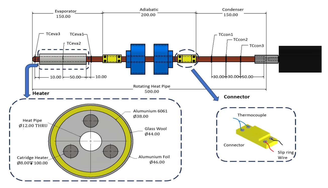
In this study, a commercial rotating heat pipe was used as a passive cooling device for an electric motor, whose detailed specifications are listed in Table 1. The pipe filled with ethanol as the working fluid has an overall length of 500 mm and is structured into three sections: a 150 mm condenser, a 200 mm adiabatic zone, and a 150 mm evaporator A schematic of RHP is presented in Figure 2 for clarity. Structurally, the RHP is mounted on the electric motor shaft through a special coupling attached to the condenser side. The evaporator side of the RHP receives heat from an external hollow tube heater equipped with three cartridge heaters. These cartridge heaters are made of 6061 aluminum with a diameter of 38 mm, and each cartridge has an internal diameter of 8 mm. To minimize heat loss from the heater to the surrounding environment, thorough insulation is carried out and glass wool and aluminum foil are applied to the entire surface of the aluminum metal. A voltage regulator is used to control the heat load supplied by the heater. The specific dimensions of the rotating heat pipe are detailed in Table 2.
Table 1 Electric motor specification.
| Parameter | Value |
|---|---|
| Voltage | 220V |
| Input | 120W |
| Output | 1/12 HP |
| Ampere | 0.6 |
| RPM | 7500 |
Temperature measurements on the RHP surface were carried out using six K-type thermocouples. Three thermocouples were placed in the evaporator section (Tevap1, Tevap2, Tevap3) and three in the condenser section (Tcond1, Tcond2, Tcond3). Tevap2 specifically measures the temperature on the RHP surface inside the heater, while Tevap1 and Tevap3 were placed outside the heated area in the evaporator section. In addition, two other thermocouples were used to monitor the heater temperature and the ambient temperature. Figure 2 shows the RHP testing equipment schematic and detailed location of temperature measurement.
Table 2 Specification of the rotating heat pipe (cylindrical).
| Parameter | Value |
|---|---|
| Diameter heat pipe | 10mm |
| Heat pipe length | 500mm |
| Adiabatic length | 200mm |
| Condenser length | 150mm |
| Evaporator length | 150mm |
| Working fluid | ethanol |
| Filling ratio | 15% |
| Material | Copper |
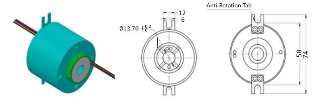
To accommodate temperature measurements on rotating components, a slip ring is used as an interface between the thermocouple mounted on the RHP and the data acquisition module. This slip ring consists of a rotor that rotates with the RHP and a stationary stator with brushes that transmit data signals. The collected temperature data is then transmitted through the slip ring to the NI-9124 module and processed using the NI LabVIEW 2018 application for realtime graphical data display on a computer. The rotational speed of the electric motor is regulated using a dimmer and measured precisely with a digital tachometer. The schematic of the rotating heat pipe test facility is shown in Figure 4. Figure 4(a) shows the schematic diagram, while Figure 4(b) presents the physical layout of the system. A detailed drawing of the rotor and stator components of the slip ring used in the experiment is provided in Figure 3.
RHP Test Equipment Schematic.
Drawings of a slip ring.
1. Computer; 2. Power Meter; 3. Voltage Regulator; 4. Heater; 5. Slip ring; 6. Thermocouples; 7. NI 9214 and cDAQ 9714; 8. Coupling; 9. Electric Motor; 10. RHP; 11. Test rig; 12. Tachometer
(a) Schematic and b. physical setup of the experimental system rotating heat pipe.
Figure 5 Schematic of RHP (H. Wang et al., 2023).
Experimental Matrix
This experiment was conducted to evaluate the performance of a rotating heat pipe (RHP) under various operating conditions by systematically varying the rotational speed and the applied heat load. The RHP was tested at rotational speeds ranging from 0 RPM (static condition) to 200 RPM, in 50 RPM increments. Simultaneously, the heat input to the evaporator section was varied between 5 W and 20 W, in 5 W increments. For each test condition, data collection began after steady state was achieved, and measurements were recorded at one-minute intervals for a total duration of 60 minutes (3600 seconds). After each data set was collected, the heating system was turned off, and the device was allowed to cool naturally to ambient temperature before the next operating test began.
Static RHP testing was carried out during daytime hours, with an average ambient temperature of 29.34°C, while dynamic (rotational) testing was conducted under ambient conditions ranging from 28°C to 30°C. The complete set of test parameters employed in this study is summarized in Table 3.
Parameter unit Value 5-20 5-20 5-20 5-20 Heat load to the evaporator W 5-20 RPM 0 50 100 150 200 Rotating speed cooling air temperature °C 29,34 29,34 29,34 29,34 29,34 Experiment time 3600 3600 3600 3600 3600
Table 3 Rotating heat pipe test matrix.
Data Calculation Methods
The thermal performance of a rotating heat pipe (RHP) is evaluated by calculating several parameters, including heating power, effective thermal resistance, and the amount of heat loss.
Heater power
Three cartridge heaters were installed to supply heat flux to the evaporator. The heating power (Q) was calculated from the voltage (U) and current (I) supplied to the heaters, measured with a multimeter. The value of Q was obtained as the product of the measured voltage and current, as shown in the following equation.
\[Q = UI (1)\]
Thermal resistance
The heat transfer performance of the RHP was assessed through its thermal resistance (R), following approaches reported in previous studies by (H. Wang et al., 2023) and (Putra & Ariantara, 2017). Thermal resistance was calculated using the relation:
\[R = \frac{T_{evap} - T_{cond}}{O} \tag{2}\] with R denotes the thermal resistance, while \(T_{evap}\) and \(T_{cond}\) are the measured temperatures at the evaporator and condenser, respectively. The parameter Q represents the heat transfer rate applied in the system.
Heat loss and effective heat input
The actual heat transferred through the RHP \((q_{RHP})\) is estimated by correcting the input power for heat losses to the surrounding environment. Heat losses are assumed to occur primarily by conduction through the insulating materials (glass wool and aluminum foil), and the efficiency of the cartridge heater is assumed to be 100%.
The total thermal resistance of the insulation system was calculated using:
\[R_{total} = R_{glass\ wool} + R_{aluminum\ foil} \tag{3}\]
\[R_{total} = \frac{\ln(\frac{r_2}{r_1})}{2\pi \, k \, L} + \frac{\ln(\frac{r_3}{r_2})}{2\pi \, k \, L} \tag{4}\]
Subsequently, get the value of \(q_{loss}\) by using the equation shown below.
\[q_{loss} = \frac{T_{glass\,wool} - T_{aluminum\,foil}}{R_{total}}\] (5)
Once the value has been obtained, the value can be calculated using the following equation.
\[q_{RHP} = q_{input} + q_{loss} (6)\]
Where is the power reading recorded by Yokogawa WT310 power meter, corresponding to the nominal values of 5W, 10W, 15W, and 20W.
Motor Rotation Speed
Furthermore, the rotation of an electric motor can be determined by utilizing the formula that is provided below in order to gain a better understanding of the phenomenon of the rotating heat pipe.
\[RPM = \frac{120 \, x \, f}{p} \tag{7}\]
In this equation, represents the number of poles that are present in the electric motor, and represents the frequency that is either already existing in the motor or is being received by the testing system.
Measurement Accuracy and Error Estimation
To ensure accurate temperature measurements throughout the experimental procedure, K-type thermocouples were employed at critical locations of the RHP. A fine-diameter thermocouple (0.3 mm) was used to measure the surface temperature of the evaporator section where the cartridge heater was applied. For the adiabatic and condenser sections, larger 0.6 mm thermocouples were mounted on the rotating component using a slip ring interface.
All thermocouples were calibrated prior to the experiment using a certified ASTM-standard thermometer across a temperature range of 0–100 °C. The calibration confirmed a temperature measurement accuracy of ±0.05 °C. The thermal data collected from these sensors was recorded using a PC-based data acquisition system (NI 9214 and CompactDAQ 9714) developed by National Instruments (NI Systems).
To regulate the heat input supplied to the evaporator, a precision voltage and current measuring device (Yokogawa WT310, accuracy 0.1%) was utilized. Based on the uncertainties in measured parameters, the uncertainty in calculated thermal resistance R is estimated using Eq. (8):
\[\frac{\Delta R}{R} = \sqrt{\left(\frac{\Delta (T_{eva} - T_{con})}{T_{eva} - T_{con}}\right)^2 + \left(\frac{\Delta Q}{Q}\right)^2}\] (8)
Based on this formulation, the overall uncertainty in thermal resistance is estimated to be within ±2%. Despite these careful preparations, several factors may contribute to deviations and noise in the temperature readings during operation. Common sources of error include improper thermocouple placement, mechanical vibration from rotation, electrical noise in the slip ring transmission, and contamination (dust or debris) at contact points. Particularly at higher rotational speeds, vibration-induced misalignment and unstable contact within the slip ring may result in fluctuating readings.
To minimize these issues, regular cleaning of the slip ring was conducted every four hours, and wire connections were checked for security before each trial. In addition, motor speed, which directly affects centrifugal force and heat distribution, was continuously monitored using a digital tachometer and manually adjusted to account for any fluctuations caused by voltage instability or mismatches between the dimmer and the motor characteristics.
Results
Experimental Conditions and Thermal Profiles
The experiments were conducted over a continuous four-hour period for each variation, with the heat load adjusted in 5 W increments after the system reached a steady state, typically within one hour. The ambient temperature was maintained between 28–30 °C throughout the tests.
The comprehensive temperature profiles of the evaporator and condenser sections as a function of heat load and rotational speed are presented in Error! Reference source not found.. A consistent trend was observed across all conditions: the surface temperatures of both the evaporator and condenser increased proportionally with each step increase in heat load, confirming a repeatable thermal response.
Effect of Rotation on Thermal Performance
Under static conditions 0 RPM, Figure 6(a), the system operated in a purely passive mode. The temperature differential (ΔT) between the evaporator and condenser ranged from 3.87 °C to 5.54 °C. This differential establishes the baseline performance against which the effects of rotation are compared. Upon introducing rotation, a significant enhancement in thermal performance was observed, particularly at lower speeds.
At 50 RPM Figure 6(b), the ΔT narrowed considerably to a range of 1.95–3.17 °C. This trend of reduced temperature differential continued at 100 RPM Figure 6(c), indicating a more efficient heat transfer mechanism compared to the static case. At these lower rotational speeds, the system reached steady state smoothly and exhibited minimal temperature fluctuations. However, as rotational speed increased further to 150 RPM Figure 6(d), early signs of thermal instability emerged. While the system maintained a positive correlation between heat load and temperature, the temperature fluctuations became more pronounced, and the ΔT began to widen, ranging from 2.84 °C to 4.17 °C.
This trend of degrading performance was most evident at the highest tested speed of 200 RPM Figure 6(e). The temperature data exhibited significant noise and instability. Notably, at a heat load of 20 W, an unintended drop in motor speed during the test resulted in a sharp increase in the evaporator temperature, followed by a delayed thermal response in the condenser. This event highlights a marked reduction in the system's stability and heat transfer effectiveness at higher rotational speeds.
Although the applied heat load appears steady during each stage, the temperature of the evaporator and condenser continues to rise for a period due to the inherent thermal inertia of the system and the time required for the working fluid to redistribute and complete phase transitions effectively. This transient thermal response delays the system from immediately reaching thermal equilibrium. Moreover, close observation of the temperature trends reveals a gradual reduction in the rate of increase as time progresses, suggesting that the system is approaching a steady state. If the heat load were held constant for a longer duration, it is expected that both the evaporator and condenser temperatures would eventually stabilize. However, in the current setup, the heat load is increased in 5 W increments after approximately one hour, preventing full stabilization before the next step begins.
Finally, across all rotating tests, signal noise in the temperature readings became progressively more apparent with increasing rotational speed. This is attributed to factors inherent in the experimental setup, such as slip ring transmission errors and system vibrations, and will be further addressed in the Discussion.
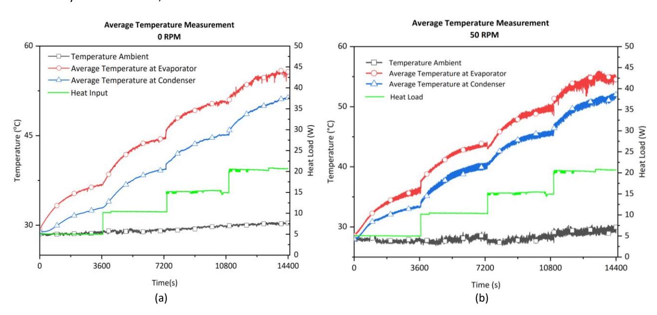
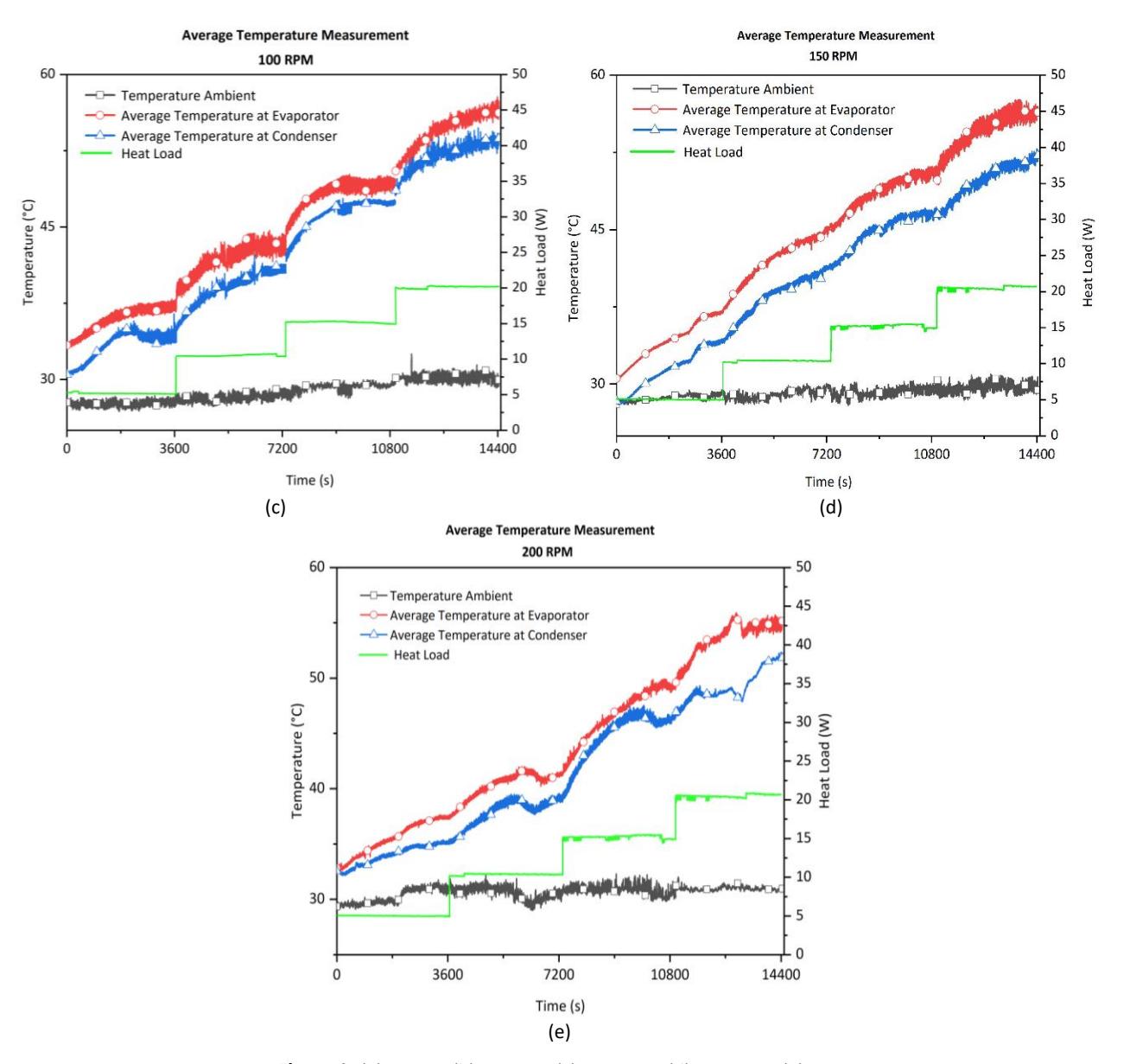
(a) 0 RPM, (b) 50 RPM, (c) 100 RPM, (d) 150 RPM, (e) 200 RPM.
Thermal Resistance
The performance of the RHP is determined by calculating the thermal resistance as the key parameter. The result of the calculated thermal resistance is provided in Figure 7.
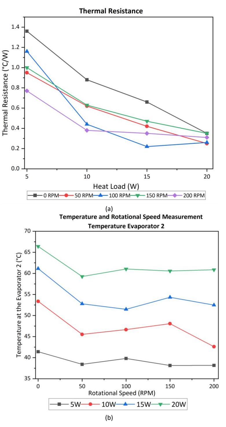
Performance of RHP based on a. thermal resistance, and b. evaporator temperature.
Figure 7(a) shows that the thermal resistance of the rotating RHP is consistently lower than the thermal resistance of the stationary heat pipe, confirming the improvement in thermal performance due to the rotation effect. Thermal resistance reduction reaches 43% at 5W, 57% at 10W, 66% at 15W, and drops to 33% at 20W. The peak performance at 15W is attributed to the optimal balance between heat input and the combined capillary and centrifugal forces, which enables efficient liquid-vapor phase change and rapid fluid circulation inside the RHP. At lower heat inputs of 5W and 10W, the thermal driving force is relatively weak, which limits the activation of internal fluid dynamics, and therefore, the heat transfer performance remains suboptimal despite rotation. In contrast, at 20W, the thermal resistance increases again, which can be attributed to a phenomenon known as capillary or centrifugal limitation. Excessive heat input can exceed the RHP's ability to efficiently recirculate the condensed liquid to the evaporator, leading to partial drying or boiling of the thin film. This condition reduces the effective contact area for heat exchange, increases the temperature difference, and consequently results in higher thermal resistance. These findings indicate that 15W is the optimal operating condition where the RHP reaches maximum thermal efficiency, where system degradation becomes apparent. Furthermore, the lowest thermal resistance was observed at 50 RPM, indicating that this speed provides the most favorable balance between capillary and centrifugal forces. At 50 RPM, the centrifugal force is strong enough to support the redistribution and return flow of the working fluid, enhancing phase change efficiency, while still allowing capillary action to function effectively. At higher rotational speeds (e.g., 100-200 RPM), the dominance of centrifugal force may disrupt fluid return pathways or cause fluid retention in the condenser region, leading to unstable flow dynamics and reduced thermal performance. Therefore, 50 RPM can be considered the optimal rotational speed under the tested conditions.
Figure 7(b) presents the temperature profiles recorded at the evaporator using the TCeva2 thermocouple. The temperature trends are consistent with the thermal resistance data, which show higher surface temperatures for the stationary heat pipe, especially at 15W and 20W. At these loads, the temperatures exceed 60°C, which is considered a critical threshold for electric motor safety. In contrast, the RHP shows better thermal regulation, indicating its potential for effective thermal management in rotating systems.
Analysis of Working Fluid Flow in RHP
The process of heat transmission is aided by the presence of a working fluid that is contained within the heat pipe and moves along the length of the heat pipe. There is no question that the working fluid flow will be affected by the rotation of the heat pipe when it is spun at a specific rotational speed.
It is anticipated that the centrifugal force that is generated within the RHP will have a beneficial effect on the performance of the RHP, particularly within the condenser location. This is because the gravitational pull will cause the working fluid of the heat pipe to gather at the bottom while the conditions are stationary.
The thickness of the working fluid layer is increased as a result of the significant volume of working fluid that has accumulated at the bottom. The thermal resistance of the working fluid is affected by the thickness of the fluid, and when the thickness of the fluid is large, the thermal resistance is also high.
The centrifugal force from the rotation drives the working fluid toward the pipe wall. As a result, the fluid layer progressively thins out. It is expected that thermal resistance will decrease as the fluid layer thins. This is consistent with previous research findings.
The rotation of the heat pipe also generates centrifugal force. This force pushes the working fluid back from the condenser to the evaporator much faster than if the fluid were moving on its own.
The results further revealed that the thermal resistance of the RHP was consistently lower than that of the stationary heat pipe, confirming the superior thermal performance of the rotating configuration. The explanation for this is that when the heat pipe is rotated at a specific speed, the working fluid, which had initially accumulated only at the bottom of the heat pipe, will distribute itself across the surface of the pipe. This distribution is the underlying cause of the phenomenon.
The experimental results presented in Figure 7a further illustrate this mechanism. As the heat load increases from 5 W to 20 W, a consistent decrease in thermal resistance is observed across all rotational speeds. Specifically, the stationary heat pipe (0 RPM) exhibits the highest resistance, exceeding 1.2 °C/W at the lowest heat load, while the rotating configuration exhibits much lower values. At moderate speeds such as 100 RPM, the resistance drops sharply as the load increases, indicating that the induced fluid circulation is very effective in distributing heat more evenly.
Comparisons across rotational speeds show that higher RPMs generally correlate with lower thermal resistance, although the trend is not completely linear. For example, the 150 RPM and 200 RPM conditions show superior performance at high heat loads, with values approaching 0.2 °C/W, which represents a reduction of up to 66% compared to the stationary condition. This performance improvement highlights the role of centrifugal force in accelerating fluid motion and enhancing phase change dynamics within the pipe.
The results of the study show that rotation prevents the working fluid from accumulating at the bottom of the heat pipe and, at the same time, improves heat transfer between the evaporator and condenser. These results support the theoretical expectation that the centrifugal effect contributes to higher heat transfer efficiency. In addition to confirming previous studies, the data also measures how rotational speed and heat load interact, offering practical insights for designing engine cooling systems that operate under a wide range of conditions.
Discussion
The findings of this study demonstrate that rotating heat pipes deliver better heat transfer efficiency than stationary heat pipes. As the rotational speed increases, thermal resistance decreases, with reductions of up to 66% recorded at 15W and 100 RPM. This improvement is mainly attributed to the enhanced fluid movement of the working fluid within the heat pipe during rotation, which promotes more uniform heat distribution and lowers overall resistance. Such results are consistent with previous research that has reported the positive effects of rotational motion on thermal performance of heat pipes.
The presence of noise, although detected during the experiments, did not appear to significantly impact the thermal efficiency of the RHP. The observed noise was caused by electrical interference and minor mechanical vibrations, but did not correlate with any substantial deviations in the thermal measurements. Although noise was present, it did not affect the accuracy of the thermal data and therefore does not weaken the study's conclusion.
Accordingly, a set of recommendations is presented to strengthen future experimental configurations.
- 1. Slip Rings: It is essential to ensure that the slip rings used in the setup are of high quality and are maintained to prevent any loose connections or contact issues. This will reduce noise and potential data errors.
- 2. Motor Control: Stable speed control is best maintained by using frequency converter or an encoder, since both help reduce the influence of power fluctuations on the motor. Low-quality dimmers, on the other hand, should be avoided because they are often incompatible with the motor specification and can introduce operational instability.
- 3. Voltage Stabilization: A voltage stabilizer is essential to provide a stable power supply during experiments, as voltage fluctuations can disrupt system performance.
Further studies should focus on assessing the scalability of RHPs, particularly by investigating their performance at higher rotational speeds (e.g. 500-2000 RPM) and by exploring the use of alternative working fluids. Furthermore, assessing how variations in physical geometry and fluid flow patterns influence RHP behavior at these elevated speeds could yield valuable insights for improving design strategies and enhancing performance in practical applications.
Improving these aspects in subsequent experiments is expected to produce more accurate and reliable outcomes, thereby providing clearer understanding of the full potential of RHP as passive cooling solutions in advanced thermal management systems.
Conclusion
This study investigates the thermal performance of a rotary heat pipe (RHP) at various rotational speeds and heat loads. The main objective is to determine how axial rotation affects heat transfer efficiency, thermal resistance, and overall operating behavior. The results showed that higher rotational speeds consistently improved heat transfer performance, indicating a clear relationship between rotation and thermal response. Specifically, experiments show that thermal resistance decreases by up to 66% under certain test conditions, representing a substantial improvement compared to a stationary heat pipe. These results highlight the potential of RHP to provide significant advantages in thermal management, especially for systems requiring effective heat dissipation under dynamic operating conditions.
While noise was observed during the experiments, it did not significantly impact the thermal performance of the rotating heat pipes. The presence of noise was considered negligible with respect to the heat transfer efficiency. However, to improve the data accuracy and system performance in future experiments, it is recommended to address the slip rings and motor controls. Additional investigation should also focus on testing under higher rotational speeds, different working fluids, and varying geometric configurations of the RHP.
Nomenclature
AROP = Axially rotating oscillating heat pipe ASTM = American society for testing and materials
cDAQ = Compact data acquisition CFD = Computational fluid dynamics EMI = Electromagnetic interference f = Frequency, Hz
HEV = Hybrid electric vehicles
HP = Heat pipe I = Current, A k = Thermal conductivity, W/m °C
L = Length, mm NI = National instrument p = Number of poles PHP = Pulsating heat pipe
PMSM = Permanent magnet synchronous motor
Q = Heater power, W q = Heat transfer rate, W R = Thermal resistance, °C/W
r = radius
RFI = Radio frequency interference
RHP = Rotating heat pipe RPM = Rotation per minute
TCcon = Temperature of condenser, °C TCeva = Temperature of evaporator, °C
U = Voltage, V
Greek Symbols
∆Q = Heater power difference, W
∆R = Thermal resistance difference, °C/W
Acknowledgment
The authors would like to thank Riset Kolaborasi Indonesia (RKI) 2023 for supporting and funding the research.
Compliance with ethics guidelines
The authors declare they have no conflict of interest or financial conflicts to disclose.
This article contains no studies with human or animal subjects performed by the authors.