
Introduction
The demand for timber beams with long spans is responsible for the wide use of beam-to-beam structural connections. Various types of beam-to-beam connections exist, including dowel-type mechanical fasteners, adhesive bonding (Tannert et al., 2012), and their combination known as glued-in rod joints (Navaratnam et al., 2022). Glued-in rod joints use dowel-type mechanical fasteners inserted into the perforated cross-section of the timber beam and bonded with a specified adhesive material. This type of connection has shown efficacy in augmenting both strength and stiffness of the jointed timber beams (Vallée et al., 2017). Additionally, dowels inserted inside the cross-section of the jointed timber beam provide two advantages, namely aesthetical appearance and protection against corrosion and fire. Figure 1 illustrates a practical implementation of a glued-in rod joint system in a construction project, demonstrating how this connection method is applied in the field to attain a long-span timber beam. Several types of dowels are used in the glued-in rod connections, including wooden dowels (Jensen et al., 2001), fiber-reinforced polymer (FRP) rods (O'Neill et al., 2017; Zhu et al., 2017), and steel rods (Ayansola et al., 2022; Steiger et al., 2007; Tlustochowicz et al., 2011). Threaded steel rods were widely used due to their ability to provide mechanical interlocking and increase the bonded area (Tlustochowicz et al., 2011). Adhesive materials commonly used are either phenol-resorcinol (PRF), polyurethane (PUR), or epoxy-resin (EPX) (Batchelar, 2004; Serrano E et al., 2008). Kemmsies (1999) investigated several types of adhesive materials for glued-in rod connections, including PRF, PUR, and EPX. The study showed that the highest pullout capacity was observed in specimens with EPX adhesive, followed by PUR and PRF.
Application of glued-in rod joint system in long-span timber beams.
Considering the advantages offered by glued-in rod joints, extensive studies have been developed. However, there are limited reports on glued-in rod joints in flexural-loaded beams. Most investigations have focused on the capacity and pull-out behavior of single (Hussin et al., 2022; Ling et al., 2019; Shekarchi et al., 2022) and multiple rods (Muciaccia, 2019; Parida et al., 2013; Thamboo et al., 2022) under axial loading. The use of glued-in rods in timber beams as beamto-beam connection was initiated by Madhoushi & Ansell (2008) who investigated the behavior of glued-in GFRP rods under fatigue loading in Laminated Veneer Lumber (LVL) beams. Furthermore, bending tests of two glulam beams connected by glued-in steel rods were conducted by Xu et al. (2012) under static loading and by Gattesco et al. (2017) under cyclic loading. The results showed that glulam beams with glued-in steel rods under static loading had superior performance in terms of stiffness, reaching the theoretical stiffness of beams without connections with the same span length. Under cyclic loading, glulam beams with glued-in steel rods provided high capacity of one energy dissipative. Meanwhile, experimental bending tests of glued-in rods on tropical timber beams are still lacking, particularly in Indonesia.
Riberholt (1988) proposed a design calculation for glued-in rod timber connections for the CIB Code. Subsequently, design methods were developed, including those proposed by Lavisci et al. (2003), Steiger et al. (2007), Rossignon & Espion (2008), and Mindrasari & Awaludin (2018). These methods focus more on the load-slip behavior of the timber beam with glued-in rod in pull-out tests. Numerical modeling with finite element analysis (FEA) for glued-in rod joints has also been conducted mostly simulating pull-out test schemes only (Grunwald et al., 2018, 2019; Hassanieh et al., 2018; Ling et al., 2018). Despite the numerous reports, numerical analysis on two timber beams jointed with glued-in rod joints subjected to bending tests is still rarely investigated. Currently, the numerical analysis for glued-in rod joints has only been reported by Xu et al. (2012). Therefore, this study aimed to examine the performance of two timber beams connected by glued-in threaded steel rods under experimental bending tests in the laboratory, with variations of diameter and anchorage length of rods. The method used was 3D nonlinear FEA with cohesive behavior to model the interaction between rods and two timber beams. The data obtained were compared with experimental results, including the behavior, failure mechanisms, and moment capacity of the jointed beams.
Experimental Program
Material and Geometry
The materials used for each jointed beam were Bangkirai (Shorea laevis) timber with dimensions of all specimens presented in Table 1. Variations in beam width, rod diameter, rod anchorage length, and existence of inserted parts of jointed beams were used to determine their effect on the behavior and capacity of glued-in rod beams. GIR B.65.16.17 indicates glued-in rod timber beams with 65 mm of width, 16 mm of rod diameter, and 170 mm of anchorage length. GIR B.65.12.25 and GIR B.110.12.25 were glued-in rod timber beams with same rod diameter (12 mm) and anchorage length (250 mm) but with different width of 65 mm and 110 mm respectively. The physical and mechanical properties of Bangkirai timber used in this study were referenced from (Ali Awaludin et al., 2025), which applied the same materials. Subsequently, four steel rods were used to join two beams with variations in diameter and anchorage length of rods presented in Table 1. The anchored length was defined as length embedded in one side of jointed beam. This was in accordance with the minimum anchorage length (lmin) required in DIN Deutsches Institut für Normung (2008), as given in Eq. (1), where d is diameter of rods. Additionally, Bangkirai timber beams and steel rods were jointed using Sikadur-31 CF Normal epoxy-resin adhesive.
\[l_{min} = maks (0.5d^2; 10d)\] (1)
| Variations | Section (mm x mm) | Each beam length (mm) | Total beam length (mm) | Diameter of rods (mm) | Anchorage length (mm) | No. of specimens |
|---|---|---|---|---|---|---|
| GIR B.65.16.17 | 65 x 190 | 1700 | 3400 | 16 | 170 | 3 |
| GIR B.65.12.25 | 65 x 190 | 1800 | 3600 | 12 | 250 | 1 |
| GIR B.110.12.25 | 110 x 190 | 1800 | 3600 | 12 | 250 | 2 |
Table 1 Specimens dimensions and variations.
Manufacturing Procedures
Bangkirai timber beams were predrilled at the center of their cross-section with four holes, namely 19 mm for GIR B.65.16.17 as well as 15 mm for GIR B.65.12.25 and GIR B.110.12.25. The holes were predrilled with 3 mm extra diameter of rods and total depth according to anchorage length given in Table 1. Specifically, for specimens GIR B.65.12.25 and GIR B.110.12.25, the end of one beam was inserted into a hollowed section of another to create a partially overlapping configuration. This configuration was intentionally designed to increase both the stiffness and strength capacity of the glued-in rod jointing system by improving mechanical interlock and load transfer efficiency. Sikadur-31 CF Normal epoxy-resin adhesive was mixed according to the instructions in the product description and immediately injected into the holes to avoid hardening of the adhesive. Steel rods were embedded into the holes in one beam and connected to the other to become GIR specimens as shown in Figure 2(a). Additionally, GIR was clamped at both ends using hydraulic jack to eliminate any gaps in the jointed parts, as presented in Figure 2(b).
(a) injected epoxy-resin and steel rods embedding (b) beam clamped using a hydraulic jack
Manufacturing process.
This process was allowed to stand for a minimum of three days to achieve optimum strength as described in the product description sheet. Joined cross-section and anchorage length of all beam types were shown in Figures 3 and 4 respectively.
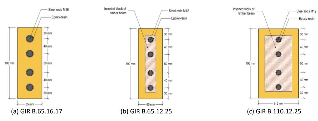
Jointed cross-section of all beam types.
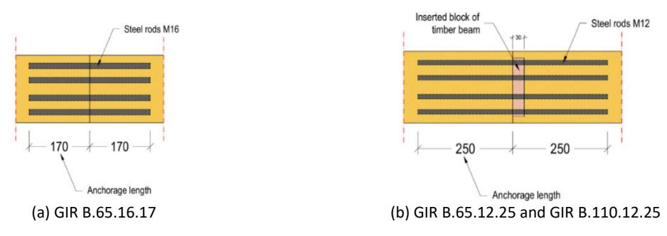
Anchorage length of all beam types.
Set-up and Protocol
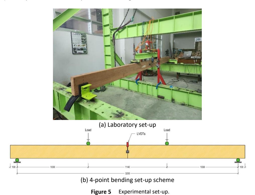
A total of six specimens of Bangkirai timber beams with glued-in rod joints were subjected to four-point bending tests. Due to the difference in specimen length, GIR B.65.16.17 used 3200 mm spans, while GIR B.65.12.25 and GIR B.110.12.25 applied 3400 mm spans with the same distance of 1140 mm between two loading points for all specimens. Although the specimen span lengths vary, this variation is acceptable as all the selected spans fall within the permissible range specified by EN 408-1995 (EN 408, 2010). Hence, the differences do not compromise the validity of the test setup or its compliance with standard structural testing requirements. A 10-ton capacity load cell was connected to a data logger to record the loading during the test. At the same time, two LVDTs were placed at the center of the beam span and connected to data logger for measuring the midspan deflection. Steel lateral supports were placed at both support points to prevent out-of-plane deformation during loading. Test set-up and loading protocol referred to EN 408-1995 (EN 408, 2010) and experimental test setup was shown in Figure 5.
Modeling of Beam Parts
Numerical Model
A 3D finite element analysis (FEA) was conducted using ABAQUS software (ABAQUS, 2018) to investigate the flexural behavior of timber beams with glued-in rod joints and compare with experimental results. The timber beam was modelled as eight-noded 3D C3D8R solid element. To investigate the interaction behavior between the surfaces of the steel rod and beam, the steel rod was modeled as a C3D8R solid element, rather than a truss element (1D element). The threads of the steel rods were not modeled, while the element was modeled as a regular cylindrical shape as shown in
Figure 6(a) and (b). According to a previous report (Ngudiyono et al., 2021), the simplification has no significant impact on FEA results compared to experimental.
Model of beam parts.
Steel bars at the support and loading points were included in the model, using the C3D8R element to model the steel bar. All elements were modeled with reduced integration and hourglass control. Subsequently, all parts passed through meshing with an appropriate mesh density, ensuring accuracy and efficiency in the developed FEA (Kyvelou et al., 2018). Fine mesh ensures accurate results but can lead to a greater size of the input file and longer computational times. According to a previous study (Hassanieh et al., 2018), the mesh size varied within each part of the model. For steel rods, mesh size was set to d/3 (d is rod diameter), while 10 mm mesh was used for timber beam parts, with global meshed model presented in Figure 6(c).
Material Properties
In a FEA, timber materials were ideally modeled as orthotropic materials (Xu et al., 2012). However, due to the limited test data of Bangkirai timber used in this study, the modeling of the material was simplified to an isotropic material. Moreover, this approach was justified based on the experimental results, where the failure primarily occurred at the epoxy-resin adhesive joint rather than within the timber itself. The modulus of elasticity (Eb) was obtained from bending test results, while the compressive strength parallel-to-the-grain (fc) was derived from compressive test results. Both tests were conducted by Awaludin et al. (Awaludin et al., 2025). Meanwhile, the Poisson's ratio (υt) was taken as 0.33 based on previous studies (Tenar et al., 2017). In this study, the material properties of the steel rod were evaluated in laboratory for yield and ultimate strength, as presented in Table 2. The elastic modulus, Es, and Poisson's ratio, υs of rods were taken as the common values of 200000 MPa and 0.2, respectively.
| Sample no. | Yield strength, fy (MPa) | Ultimate strength, fu (MPa) |
|---|---|---|
| 1 | 321.04 | 483.51 |
| 2 | 315.54 | 514.22 |
| 3 | 319.79 | 476.79 |
| Average | 318.79 | 491.51 |
Table 2 Steel rods tensile test results.
Contact and Boundary Conditions
To represent the contact between the jointed parts, timber-rods and timber-to-timber, ABAQUS contact type "COHESIVE BEHAVIOUR" was used in this model. The bond-slip relationship could be determined by traction-separation law shown in Figure 7. This law was used to determine the damage caused by linearly increasing traction until it reached a maximum value. The decreasing region showed that a failure had occurred, leading to a decrease in the bond strength between the parts. The cohesive behavior of bonded two parts can be presented by Eq. (2), where Knn is the normal cohesive stiffness and Kss with Ktt serving as the shear cohesive stiffness.
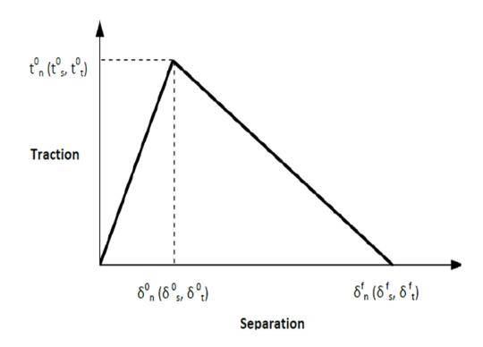
Traction-separation law ABAQUS, 2018.
{ } = [ 0 0 0 0 0 0 ]{ } (2)
Kabir et. al (Kabir et al., 2016) in Eq. (3) and Eq. (4), proposed a method to determine the stiffness coefficients as input parameters in ABAQUS. Ea is the elastic modulus of the adhesive, T0 is the thickness of the adhesive layer, and Ga is the shear modulus of the adhesive. The product data sheet of Sikadur-31 CF Normal only provides the elastic modulus, the shear modulus is estimated by Eq. (13), assuming a Poisson's ratio of 0.2. Regarding the damage mechanism, the 6 MPa bond strength value specified in the Sikadur-31 CF Normal product data sheet was adopted as the damage initiation criterion for normal and shear directions (tn = ts = tt). The key input parameters for the cohesive behavior model, including normal and shear stiffness as well as bond strength values, are summarized in Table 3.
\[K_{nn} = \frac{E_a}{T_0} \tag{3}\]
\[K_{SS} = K_{tt} = 3 \left(\frac{G_a}{T_0}\right)^{0.65} \tag{4}\]
\[G_a = \frac{E_a}{2(1+v)} \tag{5}\]
Table 3 Cohesive behavior parameters.
| Parameters | Knn (N/mm) | Kss =Ktt (N/mm) | tn = ts = tt (N/mm2 ) |
|---|---|---|---|
| Cohesive behavior | 3333.333 | 314.239 | 6.0 |
The contact between the steel bar and the timber was modeled as "HARD CONTACT" as shown in Figure 8 with a friction coefficient of 0.2 (Xu et al., 2012). Fixed boundary conditions, "ENCASTRE" boundary condition in ABAQUS, were applied to the bottom surface of the support steel bars. The two-point loads are introduced by using controlled displacements applied to the steel bars.
Contact definition between steel bar and timber beam.
Experimental Results
Load-Displacement Behavior
Figure 9 shows the load-deflection curves of experimental test results for all specimens. All beams showed similar behavior, characterized by instant small decrease in stiffness after reaching 25% of maximum load (elastic stiffness). Table 4 summarizes the elastic stiffness, maximum load, and moment capacity for each specimen. For beams with 65 mm width, GIR B.65.16.17 had an average elastic stiffness of 538.60 kNm², while GIR B.65.12.25 showed a stiffness of 809.44 kNm². The moment capacity ranged from 8.89 to 11.95 kNm for GIR B.65.16.17, and reached 16.57 kNm for GIR B.65.12.25. Meanwhile, GIR B.110.12.25 showed the highest values, with stiffness ranging from 866.46 to 1029.55 kNm² and a maximum moment capacity of 20.08 kNm.
| Specimens | Elastic Stiffness, EI (kNm2 ) | Max. Load, Pmax (kN) | Moment capacity, Mmax (kNm) |
|---|---|---|---|
| GIR B.65.16.17 (1) | 524.49 | 23.20 | 11.95 |
| GIR B.65.16.17 (2) | 516.99 | 20.56 | 10.59 |
| GIR B.65.16.17 (3) | 574.33 | 17.26 | 8.89 |
| GIR B.65.12.25 | 809.44 | 29.33 | 16.57 |
| GIR B.110.12.25 (1) | 866.46 | 35.54 | 20.08 |
| GIR B.110.12.25 (2) | 1029.55 | 23.46 | 13.25 |
Table 4 Experimental bending test results.
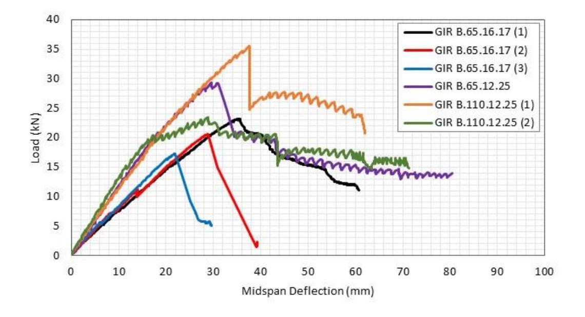
Load-displacement curves of experimental results
Failure Mechanism
For all specimens, prior to reaching the maximum load, bond between two timber beams was disrupted, causing a detachment and gap. This phenomenon was because the epoxy-resin adhesive have reached its tensile capacity. Moreover, in one specimen of GIR B.65.16.17, pull-out failure of steel rods also occurred. In top side cross-section of the beam, subjected to compressive stress theoretically, no compressive failure was observed visually. Physical failure of the rods could not be investigated, with Figure 10 showing the failures in all specimens.
(a) GIR B.65.16.17 (b) GIR B.65.12.25 (c) GIR B.110.12.25
Failure mechanism of timber beam with glued-in rod joints.
Discussions
Influence of Anchorage Length and Rod Diameter
According to Ling et al. (Ling et al., 2014), the anchorage length has a minor effect on the stiffness of beams with gluedin rod joints. A discrepancy was observed with the experimental test results presented in Table 4, where the stiffness of GIR 65.12.25 with 250 mm anchorage length (809.44 kNm2 ) was significantly greater than the average value of GIR 65.16.17 with 170 mm (538.60 kNm2 ). In this study, several influencing factors were not accounted for in the tests, such as the adhesive layer thickness, the accuracy of hole drilling for the steel rods, and the non-uniform surface contact between the steel rods and the surrounding wood fibers. These limitations may have contributed to the variations observed in the results and are recommended to be addressed in future research. However, this discrepancy did not render the experimental test results inapplicable. The stiffness of GIR 65.12.25 beam had been validated with an average value of GIR 110.12.25 (948.01 kNm2 ) beam which had the same configuration of rods, namely diameter and anchorage length, with a 17% difference. Furthermore, longer anchorage lengths were found to increase the strength of beams with glued-in rod joints, with a 58% moment capacity increase between average values of GIR B.65.16.17 (10.48 kNm) and GIR B.65.12.25 (16.57 kNm). The diameter of rods used did not significantly affect stiffness and strength of beams with glued-in rod joints (Broughton & Hutchinson, 2001; Steiger et al., 2007). Meanwhile, according to Otero Chans et al. and Ling et. al (Ling et al., 2014; Otero Chans et al., 2008), larger anchorage length of rods provided higher strength in beams with glued-in rods connections.
According to Table 4, GIR B.110.12.25 has the highest strength in the form of moment capacity compared to other specimens. This was due to the specimen cross-sectional dimension (specimen width) which was larger than the others. In two GIR specimens with the same cross-sectional dimensions, namely GIR B.65.16.17 and GIR 65.12.25, the difference in strength occurred due to the difference in the anchorage length of the rods. According to Otero Chans et al. and Ling et. al (Ling et al., 2014; Otero Chans et al., 2008), larger anchorage length of rods provided higher strength in beams with glued-in rods connections.
Comparison Between Experimental and FEA
By comparing the experimental results, FEA model successfully captured a similar load-deflection behavior, indicating that the mesh density used in numerical model provided good agreement with experimental results. Figure 11 and Table 5 showed a comparison between experimental and FEA results. In GIR B.65.16.17 specimen, the difference in elastic stiffness was very small, namely 0.6%, while GIR B.65.12.25 reached 14.6%. In terms of moment capacity, FEA model of the two GIR specimens showed higher values with difference of 8.1% and 13.7% regarding experimental results, respectively. This result was understandable considering that FEA model epoxy-resin adhesion was assumed to be perfect and evenly distributed to achieve maximum moment capacity.
In Figure 11, load-deflection curves derived from FEA did not show a decrease in stiffness. The epoxy-resin strength in the joint was reached at 39% of maximum load for the GIR B.65.16.17 beam and 76% for the GIR B.65.12.25 beam. However, stiffness degradation due to premature loss of adhesion did not occur in FEA model because of the perfect adhesive bond. This suggested that bond between steel rods and timber beams was still able to provide stiffness before achieving the adhesive strength, compared to the laboratory specimens which depend on quality of the fabrication.
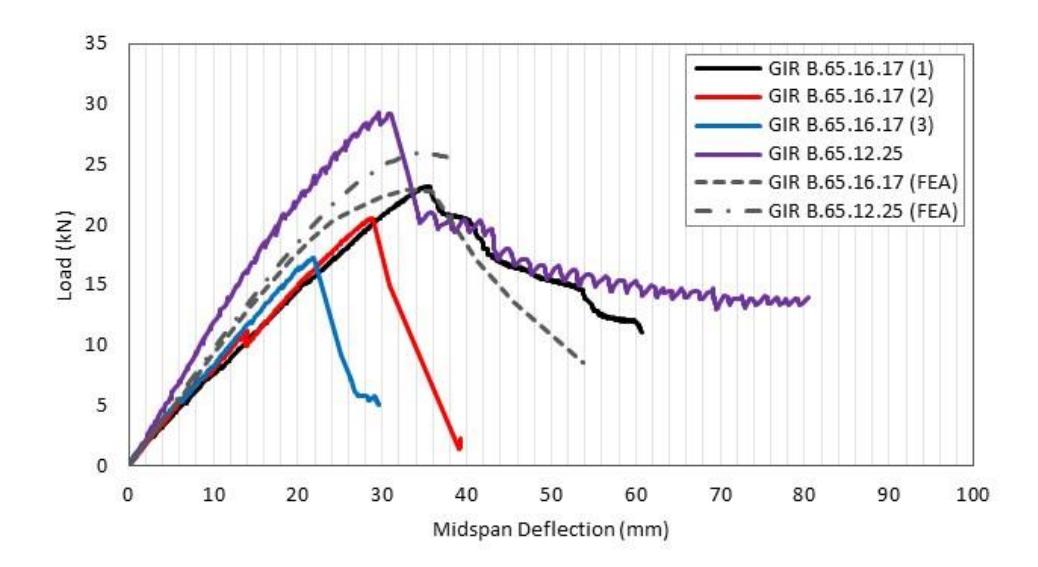
Load-displacement curves comparison of experimental and FEA results.
| Table 5 Comparison of experimental test and FEA results. |
|---|
| Specimens | Elastic Stiffness, EI (kNm2 ) | Max. Load, Pmax (kN) | Moment capacity, Mmax (kNm) |
|---|---|---|---|
| GIR B.65.16.17 (1) | 524.49 | 23.20 | 11.95 |
| GIR B.65.16.17 (2) | 516.99 | 20.56 | 10.59 |
| GIR B.65.16.17 (3) | 574.33 | 17.26 | 8.89 |
| GIR B.65.16.17 (FEA) | 541.94 (0.6%) | 23.12 (13.7%) | 11.91 (13.7%) |
| GIR B.65.12.25 | 809.44 | 29.33 | 16.57 |
| GIR B.65.12.25 (FEA) | 691.49 (14.6%) | 26.95 (8.1%) | 15.22 (8.1%) |
*number in brackets was the difference between FEA results and average experimental results
The developed numerical model using FEA was also simulated to observe progressive failures of timber beams with glued-in rod joints. Only GIR B.65.16.17 and GIR B.65.25.12 were modeled, to explore the influence of rod diameter and anchorage length on glued-in rods timber beam behavior. In GIR B.65.16.17, the first failure that occurred was a separation between two timber beams, at 39% of maximum load. This separation caused a gap at intersection of two timber beams, as shown in Figure 12(a). Subsequently, steel rods began to reach yield stress at 88% of maximum load as shown in Figure 13(a). At 100% of maximum load, pull-out failure of steel rods occurred, indicated by cohesive shear reaching shear strength of epoxy-resin and causing separation, as presented in Figure 14. This was characterized by a gap between end of steel rods and deformed timber section. Additionally, compressive stress that occurred due to contact between two timber beams at top side of cross-section had not reached the compressive strength of Bangkirai timber. The result was in line with visual observations in the experimental tests, presented in Figure 10.
GIR B65.12.25 showed similar failure behavior, starting with separation between two beams at 76% of maximum load as shown in Figure 12(b). This followed by steel rods yielding that had reached their yield strengths as presented in Figure 13(b). Therefore, the addition of inserted sections of timber beam in GIR B.65.12.25 specimen was able to increase grip between the beams, for separation to occur. Compared to GIR B.65.16.17, there was no pull-out of steel rods in GIR B.65.12.25 beams when the load reached its maximum but the steel rods continued to yield. Among the two variables that differentiate types of beams, the influence of anchorage length was more dominant in relation to the failure behavior that occurred. This result was in line with the study by Malczyk (Malczyk, 1993) which showed different failure behavior in varying anchorage lengths of beams with glued-in rod joints. Steel rods with 130 mm anchorage length experienced pull-out failure. Meanwhile, tensile failure occurred at 300 mm anchorage length, indicating ductile failure in joints. According to Steiger (Steiger et al., 2007), the different dowel diameters used in beams with glued-in rod joints had no significant effect on the failure behavior.
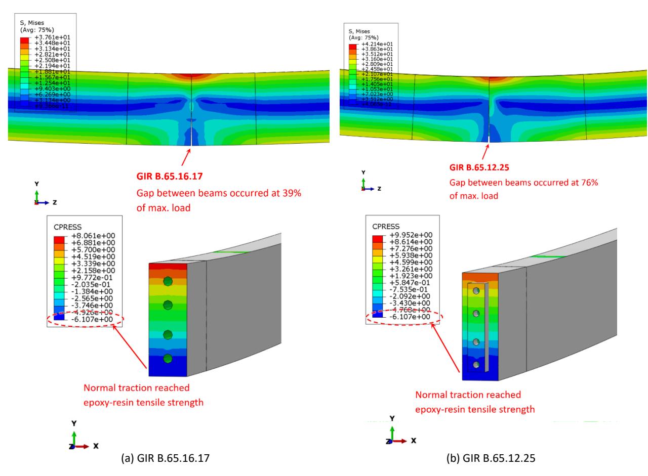
First gap occurred between the beams.
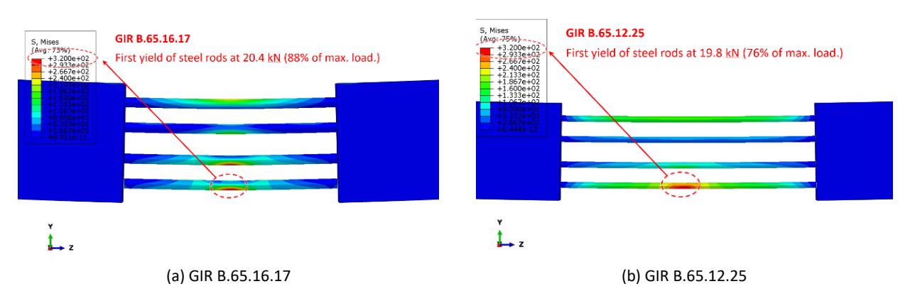
First yield of steel rods.
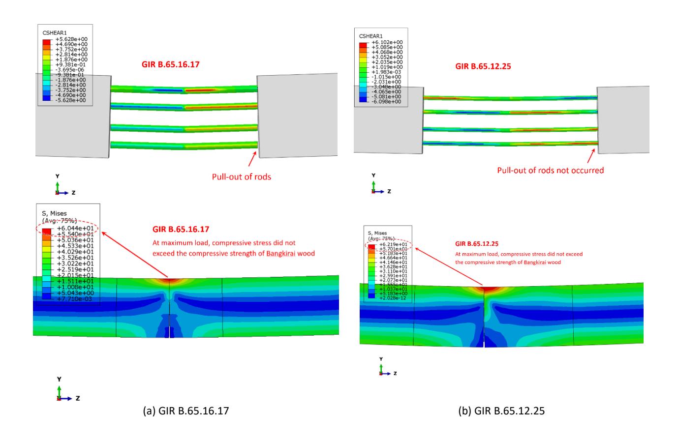
Failure behavior at maximum load.
Conclusions
This study investigated the flexural behavior of Bangkirai timber beams jointed with glued-in threaded steel rods through experimental test and FEA. The results showed that the primary failure mechanism was the separation of timber beams due to the loss of epoxy-resin adhesion, with pull-out failure of steel rods occurring in some cases. The anchorage length of the rods was found to significantly influence the moment capacity and failure behavior of the jointed beams, while the rod diameter had a negligible effect. Longer anchorage lengths improved joint strength and prevented premature pull-out failure. The developed finite element model successfully captured the load-displacement behavior of the jointed beams and provided reasonable agreement with the experimental results. However, the model assumed perfect bonding of epoxy-resin, which caused a slightly overestimated moment capacity compared to experimental results. Future studies should consider incorporating orthotropic material properties to enhance the accuracy of numerical simulations and better reflect the mechanical behavior of timber beams with glued-in rod joints.
Acknowledgment
The authors are grateful to Mr. Henry Effendy of Timber Solution Indonesia for providing the test specimens in this study. Furthermore, the authors are grateful to Mr Jarwanto Nugroho, Mr Sukino, Mr Haryanta, Mr Eko Suroyo, Mr Gatra Dewa Oktananda, and Mr Ferry for individual support and laboratory work.
Compliance with ethics guidelines
The authors declare they have no conflict of interest or financial conflicts to disclose.
This article contains no studies with human or animal subjects performed by the authors.