
Introduction
Bandar Lampung, a city facing escalating environmental challenges, is the focus of this research. The Ministry of Environment and Forestry has even designated it as the dirtiest major city in the region. The city's waste management crisis is one of its most critical ecological issues, centered on its sole final disposal site, the Bakung landfill. Established in 1994 and covering an area of 14 hectares, the Bakung landfill was initially operated using the sanitary landfill system but eventually reverted to an open dumping system was later introduced due to practical constraints. This open dumping practice has become the primary environmental concern because of the pollution it has generates. The inoperability of the leachate pond presents a second major issue. The management pond at the Bakung landfill. A was designed with a drainage and evaporation system; however, evaporation from this system resulted in contamination of residents' water supplies. Leachate has also infiltrated wells and rivers, where waste discharge seeps into the aquifer. Given these conditions, it is necessary to develop an approach to map leachate contamination and assess water quality around the Bakung landfill.
A potential solution to the problems at the Bakung landfill can be achieved through geophysical and hydrogeochemical studies. Geophysical surveys are valuable for mapping leachate plumes and determining the geometric properties of buried waste. The geoelectrical resistivity method is the most widely used geophysical technique for investigating groundwater contamination and has been successfully applied by (Giang et al. 2018), (Tresoldi et al., 2019). Meanwhile, hydrogeochemical studies help identify the main hydrogeochemical mechanisms that control the chemistry of contaminated groundwater. Such studies benefit from the analysis of the chemical composition of leachate
Copyright by authors ©2026 Published by IRCS - ITB J. Eng. Technol. Sci. Vol. 58, No. 2, 2026, 149-165
contaminants and water quality parameters. Water quality assessments using physicochemical parameters at the Bakung landfill have been conducted by (Iryani et al. 2019), along with hydraulic by (Farishi & Setiawan, 2019).
Although several studies have evaluated groundwater quality around the Bakung landfill, no integrated contamination assessment has been reported. Existing investigations (e.g., Iryani et al., (2019); Farishi and Setiawan, (2019)) are remain limited in scope. Therefore, it is essential to provide information on the characteristics of Bakung leachate based on disposal composition and to analyze its impact on surrounding groundwater. This study integrates vertical electrical sounding (VES), electrical resistivity tomography (ERT), and hydrogeochemical analyses at two different times, during the dry and wet seasons. The aims are to monitor leachate, identify the physical and chemical characteristics of groundwater, and determine hydrogeochemical facies across seasons. Furthermore, this research is novel because it examines the relationship between resistivity and precipitation, as well as resistivity and Cl- concentration, at the Bakung landfill. It is expected that the findings will contribute to improved groundwater management and protection strategies for the Bakung landfill.
Geology and Hydrogeology
The regional geology and hydrogeology of the Bakung landfill were obtained from the regional map of Tanjung Karang (Mangga et al., 1993) and the hydrogeology map of Lampung Province published by Pamsimas (2017). According to the Tanjung Karang regional geological map shown in Figure 1, the Bakung landfill is situated within the Tarahan Formation (Tpot), which is predominantly composed of breccias and massive tuffaceous rock units with chert interbeds. The Tarahan Formation is dated to the Paleocene-early Oligocene and represents a late Tertiary sequence.
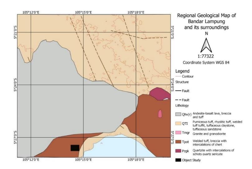
Regional geological map of Bandar Lampung (modified by Mangga et al. 1993). The Bakung landfill is located in the Tarahan Formation (Tpot), which consists mainly composed of breccias and massive tuffaceous rock units with chert deposits.
Data and Methodology
This research was carried out at the Bakung landfill and its surrounding areas in Bandar Lampung City. Geoelectrical resistivity and hydrogeochemical surveys were conducted between October and November 2021 (wet season) and July 2022 (dry season). The monthly mean rainfall at the research site is presented in Figure 2. This study employed hydrogeochemical analyses and geoelectrical resistivity techniques. In addition, well drilling was conducted to obtain soil and core samples at several geoelectrical resistivity measurement locations to collect subsurface data. The layout of drilling points, hydrogeochemical sampling locations, and geoelectrical resistivity survey designs is shown in Figure 3.
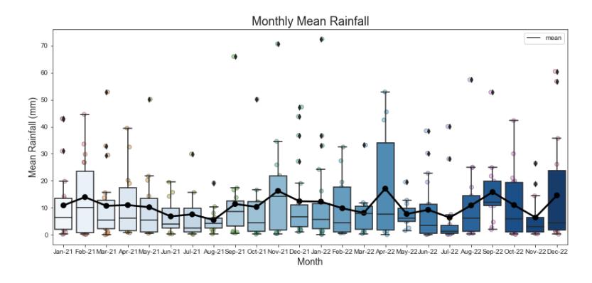
Monthly mean rainfall in Bandar Lampung from January 2021 to December 2022. The highest rainfall occurred in October-November 2021, while the lowest rainfall occurred in July 2022.
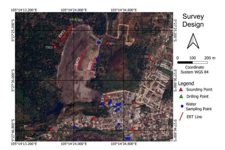
Survey design showing eight vertical electrical sounding points (red triangles), four electrical resistivity tomography lines (red lines), and fourteen water sampling points (blue circles).
Geoelectrical Resistivity
This study employed Vertical electrical sounding (VES) and Electrical Resistivity Tomography (ERT) to conduct geoelectrical resistivity measurements. In VES, also known as the 1-D geoelectrical method, direct current (DC) is injected into the ground surface to investigate subsurface electrical resistivity. The VES survey in this research, used a Schlumberger array with eight sounding points, a maximum AB/2 spacing of 125 meters, and an MN/2 spacing ranging from 0.5 to 10 meters. The Schlumberger configuration was selected because it can image is capable of imaging vertical resistivity variations at both shallow and deeper levels. As the distance between the current electrodes increases current streamlines penetrate deeper depending on the vertical conductivity distribution, allowing measurements at greater depths.
The apparent resistivity values obtained in the field represent the raw sounding sounding data. To determine the true resistivity distribution, inversion modeling was applied. Inversion begins by inputting observational data, constructing an initial model, and iteratively minimizing the misfit function between the model parameters and the measured data (Menke, 2012). This study used the damped least-squares method to interpret the sounding curves. In damped leastsquares inversion, the fit between the data and the model parameters is controlled by applying damping values, with errors from previous iterations incorporated into the broader error estimation. Menke (2012) describes the underdetermined nature of the damped inversion problem. The MATLAB script used in this study for damped leastsquares inversion was adapted from Ekinci and Demirci (2008) and implemented following Waruwu et al. (2022) and Rizka et al. (2023).
Electrical Resistivity Tomography (ERT) refers to resistivity mapping or profiling. Two-dimensional ERT combines lateral profiling and VES principles to produce 2D subsurface images. The main advantage of 2D measurements is their high vertical and lateral resolution along the profile.
In this research, four ERT survey lines were conducted using the Wenner configuration, with an inter-electrode spacing (a) of five meters and traverse lengths of 75, 105, and 115 meters. The ERT lines were positioned across key locations of the Bakung landfill: one line directly within the landfill area, one near the leachate pond, one near the black water pond, and one line positioned outside the landfill as a non-landfill comparison. The data processing parameters used for ERT are presented in.
| Line | Length | Penetration (m) | Modeling | Objective Function | Minimization Algorithm | Iteration |
|---|---|---|---|---|---|---|
| ERT-1 | 100 | 16 | Finite Difference | Marquardt & Occam | Gauss-newton | 5 |
| ERT-2 | 115 | 20 | Finite Difference | Marquardt & Occam | Gauss-newton | 5 |
| ERT-3 | 115 | 20 | Finite Difference | Marquardt & Occam | Gauss-newton | 5 |
| ERT-4 | 75 | 12.5 | Finite Difference | Marquardt & Occam | Gauss-newton | 5 |
Table 1 Data processing parameters for electrical resistivity tomography.
Hydrogeochemical
A total of fourteen water samples with depths ranging from two to fifty meters were collected for this study. These consisted of one leachate sample, one river water sample, eight dug well samples, and four drilled well samples. The selection of sampling points was based on the availability of wells surrounding the Bakung landfill. During on-site sampling, basic water quality parameters were measured, including pH, temperature, salinity, total dissolved solids (TDS), electrical conductivity (EC), and redox potential (ORP). The collected samples were then analyzed in a laboratory using ion chromatography (IC) to obtain a comprehensive ion profile.
Results
Geoelectrical Results around the Dump Sites
Based on the VES processing results (Figure 4), variations in resistivity were observed across the upper soil layers, while the deeper layers also exhibited differing values. Tuff rock in the area is characterized by resistivity values of less than 40 Ωm. Resistivity measurements near the Bakung Landfill leachate discharge flow (TSD-5) range from 9.55 to 82.61 Ωm in the wet season and from 12.3 to 66.12 Ωm in the dry season. Resistivity values near the Bakung Landfill itself (TSD-1, TSD-2, TSD-3) range from 1.99 to 116.01 Ωm during the wet season and from 1.8 to 188.47 Ωm in the dry season. Other locations (TSD-4, TSD-6, TSD-7, TSD-8) show resistivity values between 0.88 and 372.31 Ωm in the wet season and between 0.82 and 332.87 Ωm in the dry season.
When ERT measurements were incorporated—particularly the profile aligned directly across the waste disposal area the contaminant interpretations obtained from the VES data were refined accordingly. Tuff layers are considered susceptible to contamination due to their hydrogeological characteristics. According to Reiner et al. (2002), tuff typically exhibits low permeability but relatively high matrix porosity. Because of this combination, tuff layers readily admit leachate infiltration, allowing contaminants to migrate through pore spaces and enter the subsurface.
Resistivity values near the Bakung Landfill leachate discharge flow (TSD-5) range from 9.55 to 82.61 Ωm in the wet season and 12.3 to 66.12 Ωm in the dry season. Resistivity values near the Bakung Landfill (TSD-1, TSD-2, TSD-3) range from 1.99 to 116.01 Ωm in the wet season and 1.8 to 188.47 Ωm in the dry season. Other locations (TSD-4, TSD-6, TSD-7, TSD-8) show resistivity values in the wet season between 0.88 to 372.31 Ωm and in the dry season between 0.82 to 332.87 Ωm.
Rocks exhibiting resistivity values greater than 40 Ωm are interpreted as volcanic breccia. Volcanic breccia consists of angular volcanic fragments larger than 2 mm embedded within a matrix of variable composition and texture, or alternatively, rock fragments contained within a volcanic matrix. Volcanic breccia is formed through explosive volcanic activity associated with magma extrusion (Shukla and Sharma, 2018). The presence of this lithology in the research area is supported by regional geological data (Mangga et al., 1993) as well as core samples obtained from borehole drilling.
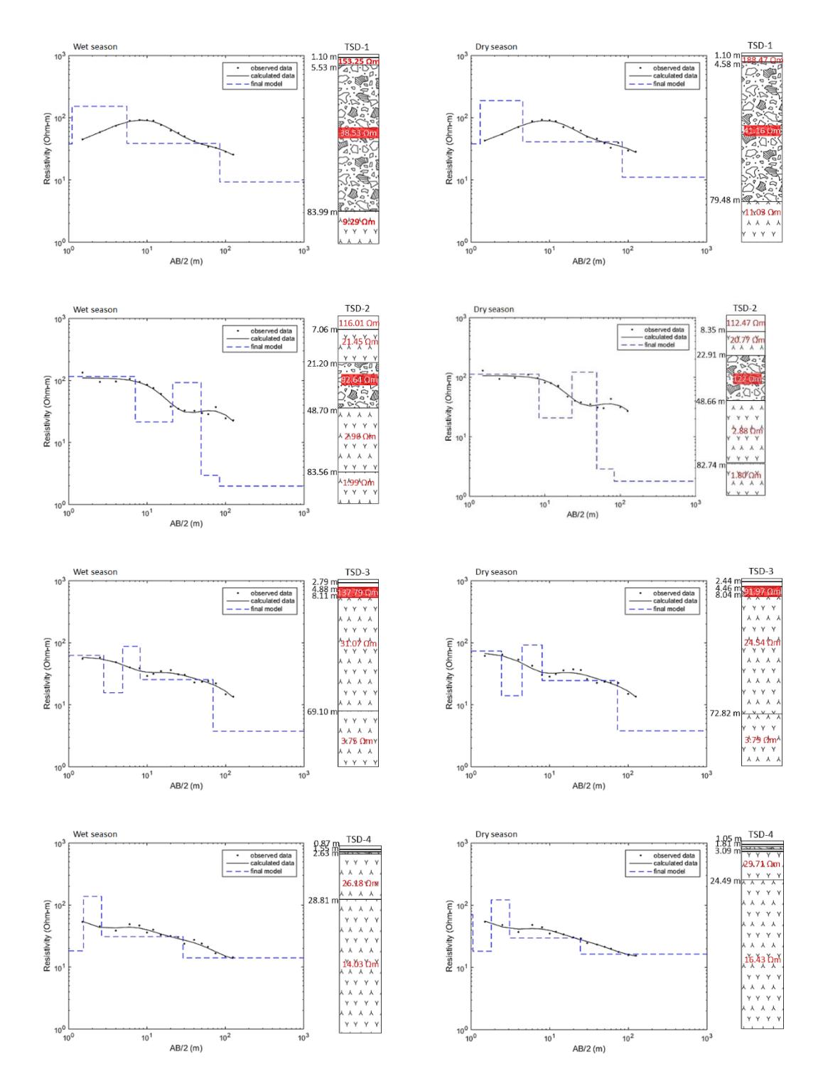
1-D resistivity model from TSD-1, TSD-2, TSD-3, TSD-4, TSD-5, TSD-6, and TSD-7, TSD-8 during the wet and dry seasons. In general, the measurements from both seasons show the same number of layers, differing only in layer thickness.
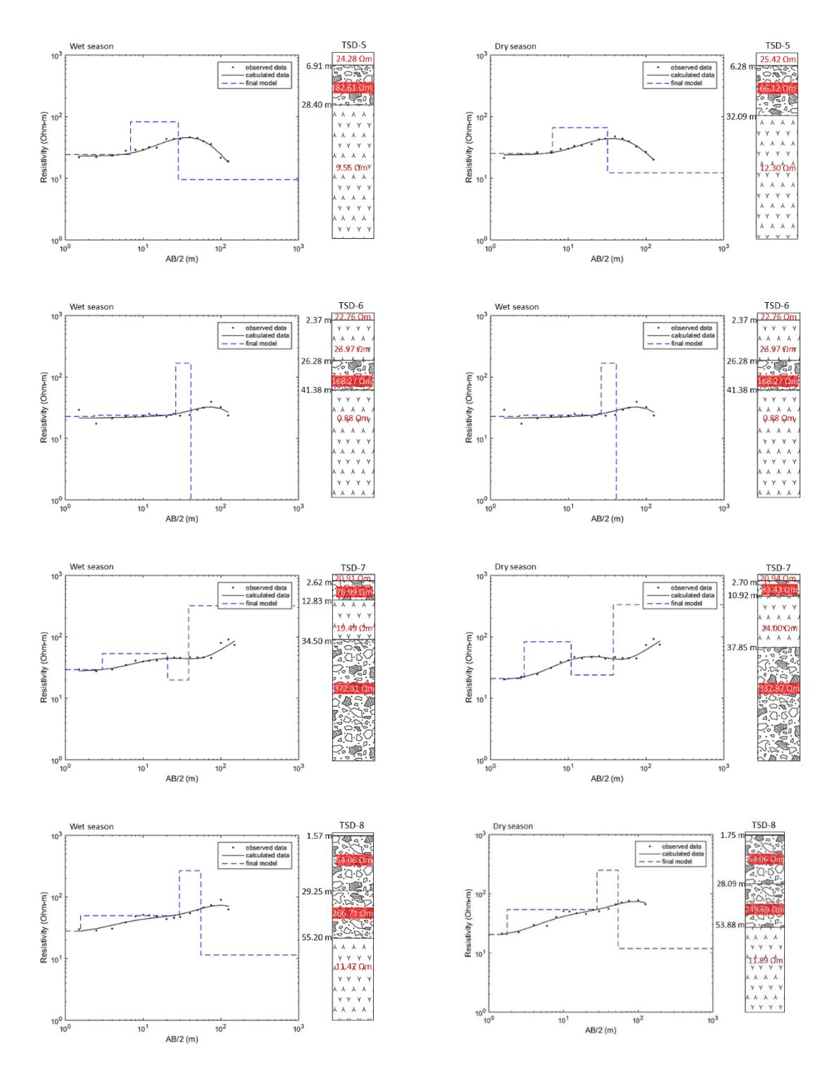
Figure 4 Continued. 1-D resistivity model from TSD-1, TSD-2, TSD-3, TSD-4, TSD-5, TSD-6, and TSD-7, TSD-8 during the wet and dry seasons. In general, the measurements from both seasons show the same number of layers, differing only in layer thickness.
The core sampling results at the Bakung landfill, particularly at the TDS-2 sounding point, show clear variations in the soil and rock layers (Figure 5). At the 0–0.8 m depth, dark brown and smooth soil samples are found, indicating the A horizon (topsoil). At 0.8–3.7 m, reddish-brown samples containing minerals represent the B (subsurface) horizon. At 3.7–4.5 m, light brown soil with minimal mineral content marks the BA (transitional) horizon. Going deeper, at 4.5–5.8 m, reddish-brown mineral-bearing samples characterize the B horizon. At 5.8–7 m, brown, finely structured mineralrich samples represent the C horizon (weathered rock). Finally, at 7–8 m, tuff with a light color, medium-fine grain size, compactness, glassy minerals, and fused pumice fragments is encountered.
The main observations include petrographic cuts, coarse grain sizes (0–1 mm) to fine sand (0–125 µm), open packing, and poor sorting, with no detected changes. The rock comprises quartz, feldspar, ash/lithic fragments, and plagioclase. Based on the classification by Pettijohn (1975), the rock is identified as crystal tuff. At the 8–9.4 m depth, white and smooth tuff is found. Its texture shows open packing, poor sorting, no variation, and grain sizes ranging from coarse (0.5–1 mm) to very fine sand (0.0625–0.125 mm). The rock composition consists of ash/lithic fragments, feldspar, quartz, matrix, and glass. According to Pettijohn (1975), the rock is classified as vitric tuff. Smooth, gray-colored tuff occurs at 9.4–10 m, with open packing, poor sorting, no variation, and grain sizes from coarse (0.5–1 mm) to very fine sand (0.0625–0.125 mm). The rock is composed entirely of matrix.
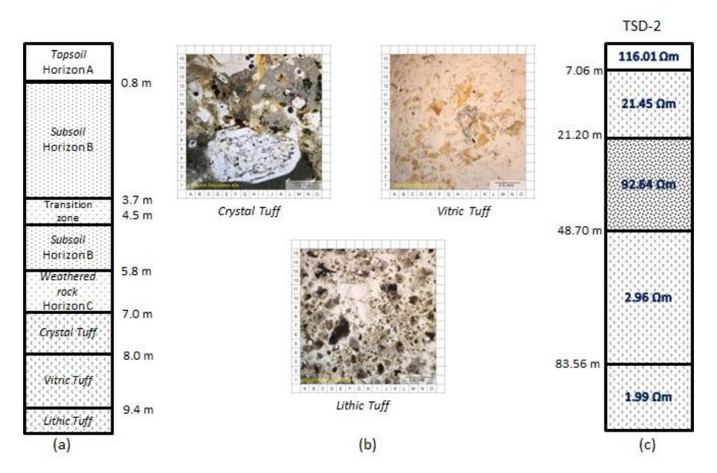
Comparison of borehole data (a), petrographic thin section (b), and rock estimates from TSD-2 sounding data (c). The borehole depth is limited to 10 m, so comparison is only possible up to that depth. Petrographic thin sections were used to confirm the rock type found in the borehole.
Around the Bakung landfill, specifically near the planned black-water pond, lies the 100-meter-long ERT-1. Based on inversion modeling results for the wet season (Figure 6.a) and the dry season (Figure 6.b), the upper layer has a resistivity value of 20–200 Ωm, representing a saturated waste zone that corresponds to the unsaturated leachate zone. The saturated waste zone contains groundwater, unsaturated soil, and waste. The lower layer shows low resistivity values, identifying it as the leachate plume zone. The modeling results indicate that the plume originates from the northeast and northwest and likely migrates into deeper layers. The intermittent zone lies between the leachate plume and the waste-containing zone (Butt et al., 2022) and connects to a high-conductivity zone located below the lower limit of solid waste.
The 115-meter-long ERT-2 is located directly inside the Bakung landfill. Based on inversion modeling during the wet season (Figure 6.d) and the dry season (Figure 6.e), and its correlation with soil sampling, the top layer—consisting of mixed waste and leachate—has a resistivity value of 13–35 Ωm. The leachate plume zone forms the lowest layer. Because this measurement line traverses waste that has accumulated for more than 25 years, the leachate plume zone extends to considerable depths. The ERT results indicate that plume migration likely originates from the northeast and northwest and moves toward the lower layers.
To the west of the Bakung landfill is the 115-meter-long ERT-3. Based on inversion modeling during the wet season (Figure 6.g) and the dry season (Figure 6.h), and supported by soil sampling correlations, the top layer—representing the B-horizon soil zone—has a resistivity value of 20–200 Ωm and is soft like clay. The lower layer contains the leachate plume zone, which is also expected to migrate from the northeast and northwest.
Downstream of the landfill and near the Bakung leachate pond lies the 75-meter-long ERT-4. Based on inversion modeling during the wet season (Figure 6.j) and the dry season (Figure 6.k), together with soil sampling correlations, the leachate plume zone is expected to migrate from the upper to the lower layers. This leachate zone extends from the ground surface to a depth of 12.5 m. On the right side, the A-horizon soil zone is more fragile and has a resistivity of 20–200 Ωm, with dark brown soil.
Figure 6 presents the results of time-lapse resistivity. Based on the time-lapse resistivity modeling, ERT-1 exhibits percentage resistivity changes ranging from −38.5% to 105%, ERT-2 from −74.1% to 635%, ERT-3 from −59.7% to 581%, and ERT-4 from −53.9% to 49%. These results indicate fluid migration from high-anomaly contours toward low-anomaly contours.
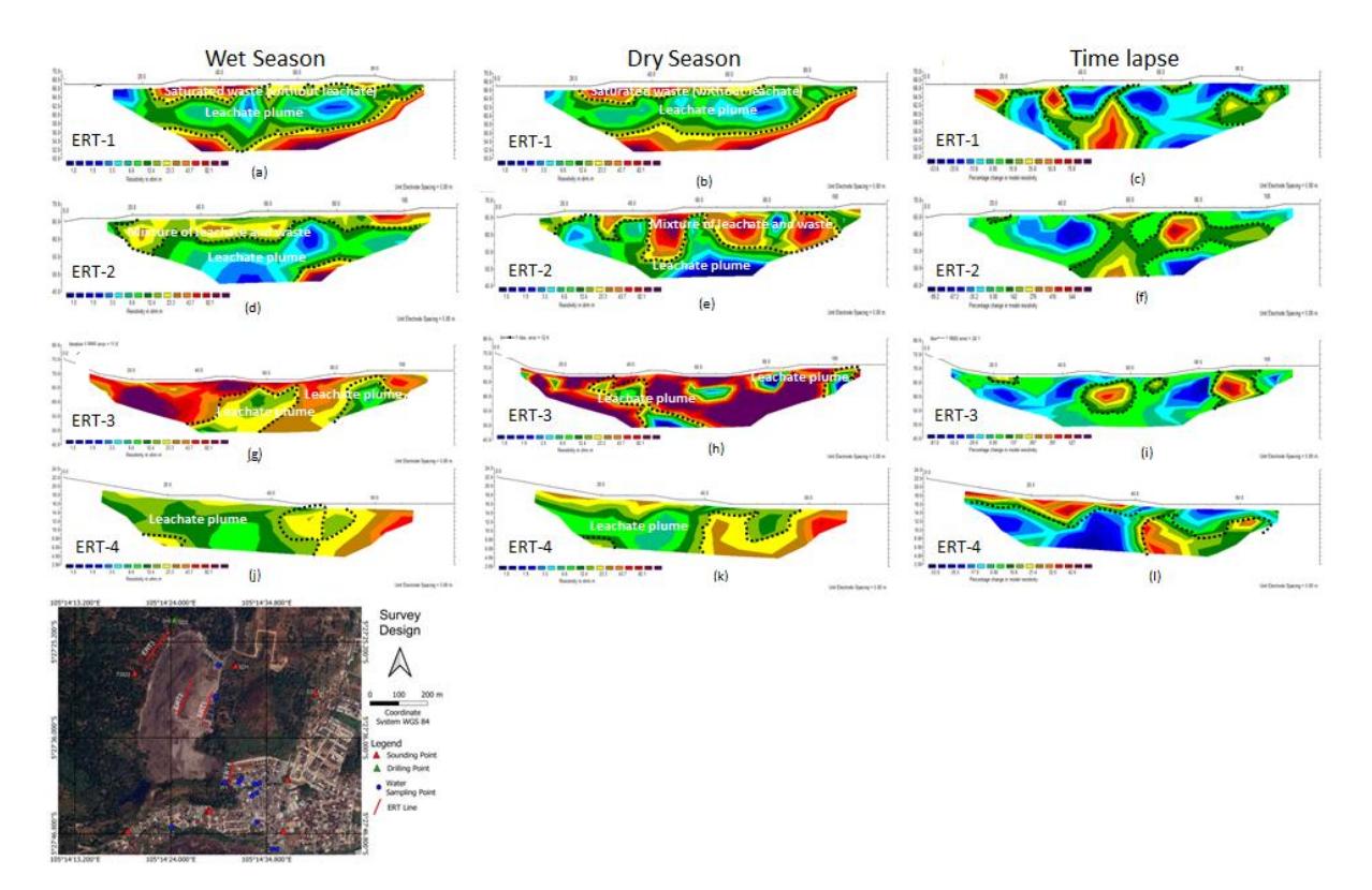
2-D resistivity images obtained from the ERT-1, ERT-2, ERT-3, and ERT-4 profiles during the wet and dry seasons. In general, the model representations for both seasons are similar. However, the representation of the ERT-2 line differs. This is because ERT-2 is located at the center of an active waste disposal site. During the subsequent assessment in the dry season, waste accumulation increased at the landfill center, resulting in a thicker near-surface layer composed of mixed waste and leachate in the resistivity model. Figures c, f, i, and l illustrate the time-lapse resistivity, showing the differences between the first and second assessments.
Hydrogeochemical around the Dump Sites
Fourteen water samples were collected for this research. A water quality meter was used on-site to measure the physico-chemical parameters at each observation point. Table 2 presents the results. According to the Regulation of the Minister of Health of the Republic of Indonesia (2023), the threshold value of TDS suitable for drinking water is 300 ppm. Field sampling data show that wells W-01 (leachate), W-05, W-06, W-07, W-08, W-12, W-13, and W-14 have TDS values exceeding 300 ppm. This indicates that these wells contain high concentrations of inorganic and organic solids such as minerals, salts, and metals, making the water unfit for human consumption due to potential health risks.
The leachate exhibits a relatively high pH value, suggesting the presence of acetogenic conditions that trigger exothermic reactions, resulting in elevated residual temperatures. In contrast, the groundwater near the Bakung landfill is slightly acidic, indicating that contamination is highly localized due to strong attenuation processes.
Ion chromatographic analysis shows that water in the Bakung dump contains major ions, including Ca²⁺, Mg²⁺, Na⁺, K⁺, HCO₃⁻, Cl⁻, SO₄²⁻, and NO₃⁻. Leachate also contains additional elements, such as chloride (Cl⁻), which is commonly associated with various waste materials. The concentration of Cl⁻ in the leachate is higher than that of SO₄²⁻. This occurs when sulfate is reduced to sulfide by microorganisms, indicating that the leachate is in the methanogenic phase (Castañeda et al., 2012).
The SO₄²⁻ content in leachate mainly originates from anaerobic sulfide oxidation, degradation of organic sulfur, dissolved waste, synthetic detergents, and dissolved sediment. Many organic compounds contain sulfur in the form of sulfate, sulfonate, or sulfide. Under anaerobic conditions, such materials release organically bound sulfur as sulfate ions.
Table 2 Measurement results of the physico-chemical parameters.
| pH | EC (μS/cm) | TDS (ppm) | Salt (%) | ORP (mV) | ||||||
|---|---|---|---|---|---|---|---|---|---|---|
| Sample ID | Wet | Dry | Wet | Dry | Wet | Dry | Wet | Dry | Wet | Dry |
| Season | Season | Season | Season | Season | Season | Season | Season | Season | Season | |
| W-01 (leachate) | 8.48 | 8.26 | 0.01 | 15.64 | 6880.00 | 7830.00 | 0.67 | 0.80 | -50.00 | -22.00 |
| W-02 (river) | 8.47 | 8.00 | 122.00 | 191.00 | 62.00 | 295.00 | 0.00 | 0.00 | 61.00 | -14.00 |
| W-03 (boreholes) | 7.80 | 6.10 | 461.00 | 194.00 | 234.00 | 297.00 | 0.02 | 0.00 | 4.00 | 12.00 |
| W-04 (boreholes) | 7.20 | 5.89 | 182.00 | 155.00 | 90.00 | 277.00 | 0.00 | 0.00 | 43.00 | 81.00 |
| W-05 (dug well) | 7.40 | 7.11 | 749.00 | 742.00 | 374.00 | 371.00 | 0.03 | 0.03 | -54.00 | 15.00 |
| W-06 (boreholes) | 6.90 | 6.70 | 1181.00 | 1065.00 | 590.00 | 534.00 | 0.05 | 0.05 | 61.00 | 84.00 |
| W-07 (dug well) | 7.27 | 6.96 | 640.00 | 785.00 | 320.00 | 384.00 | 0.03 | 0.03 | -64.00 | 36.00 |
| W-08 (dug well) | 6.90 | 7.10 | 868.00 | 730.00 | 435.00 | 365.00 | 0.04 | 0.03 | -50.00 | 16.00 |
| W-09 (dug well) | 7.64 | 7.00 | 406.00 | 434.00 | 203.00 | 215.00 | 0.02 | 0.02 | -100.00 | 82.00 |
| W-10 (dug well) | 7.31 | 7.03 | 416.00 | 483.00 | 204.00 | 240.00 | 0.02 | 0.02 | 140.00 | -17.00 |
| W-11 (dug well) | 7.28 | 6.35 | 588.00 | 539.00 | 294.00 | 296.00 | 0.02 | 0.02 | 50.00 | -25.00 |
| W-12 (dug well) | 7.34 | 6.58 | 630.00 | 662.00 | 310.00 | 355.00 | 0.03 | 0.03 | 135.00 | 17.00 |
| W-13 (dug well) | 7.26 | 7.24 | 565.00 | 662.00 | 283.00 | 331.00 | 0.02 | 0.03 | 144.00 | -4.00 |
| W-14 (boreholes) | 7.20 | 6.50 | 890.00 | 1190.00 | 445.00 | 597.00 | 0.04 | 0.05 | 105.00 | 75.00 |
| Min | 6.90 | 5.39 | 0.01 | 15.64 | 62.00 | 215.00 | 0.00 | 0.00 | -100.00 | -25.00 |
| Max | 8.48 | 7.76 | 1181.00 | 1190.00 | 6880.00 | 7830.00 | 0.67 | 0.05 | 144.00 | 84.00 |
| Mean | 7.46 | 6.42 | 549.86 | 560.55 | 766.00 | 884.79 | 0.07 | 0.02 | 30.36 | 24.00 |
| Standard deviation | 0.49 | 0.65 | 320.86 | 343.97 | 1765.25 | 2001.69 | 0.17 | 0.02 | 83.44 | 40.88 |
| Regulation of the Minister of Health of the Republic | 6.5-8.5 | 300 | ||||||||
| of Indonesia | ||||||||||
| WHO | 7.5-8.5 | |||||||||
The comparatively higher concentration of Na⁺ relative to Ca²⁺ and Mg²⁺ may be influenced by ion exchange processes (Surinaidu et al., 2022). Because groundwater in the lateritic zone is of the bicarbonate type, its HCO₃⁻ content is higher than that of Cl⁻ and SO₄²⁻. During the methanogenic phase, the concentrations of K⁺ and Mg²⁺ in the leachate decrease due to increased pH and the reduced amount of dissolved organic matter capable of forming complexes with cations. The influence of sorption, complexation, and precipitation processes in both the acidic and methanogenic phases contributes to the higher Na⁺ and K⁺ content in the leachate. These cations may originate from desorption from clay and from chemical sources within the waste. If the cations originate from inorganic compounds in the waste, the concentrations of Cl⁻ and SO₄²⁻ may also be elevated. Desorption from clay may serve as a major source of these cations, as the large amounts of ammonium generated in the leachate can be exchanged with cations contained in the clay used as daily cover material.
The elevated Na⁺ and K⁺ levels in the leachate result from sorption, complexation, and precipitation processes occurring in both the acidic and methanogenic phases. These cations may originate from chemical components in the waste and from clay desorption. If inorganic waste compounds are the source of the cations, Cl⁻ and SO₄²⁻ concentrations may
also increase. Clay desorption can serve as an important source because large amounts of ammonium produced in the leachate can exchange with cations present in the clay used to cover the waste (Kjeldsen et al., 2002).
Hydrogeochemical Facies
The mixed Ca–Mg–Cl type represents most of the water samples, as shown in the Piper diagrams for the wet season (Figure 7) and dry season (Figure 8). The Na⁺–Cl⁻ type found in the leachate sample (W-01) suggests the presence of salts—specifically, what is typically referred to as saline conditions. In the anion triangle, the bicarbonate type and sample W-05 show no dominant species, while the cation triangle also shows no dominant type. Due to contamination from the landfill, sample W-01 falls under the Cl⁻ type. Water–rock interaction in the area produces a Ca–HCO₃ groundwater type. Because the research area is composed of volcanic rocks, groundwater interacts with mineral components in the aquifer as it flows through the formation. CO₂ dissolved in rainwater infiltrates the soil, further dissolving into the system and serving as the primary source of HCO₃⁻ ions in groundwater.
Cl⁻ is present in both the NaCl and mixed Ca–Mg–Cl groundwater facies, which is likely attributed to leachate enrichment of the aquifer with NaCl. High Cl⁻ and Na⁺ concentrations in the leachate indicate significant dissolved salts in municipal waste. As reported by Gemilang et al. (2022), chlorine-bearing paper and plastics are major sources of chlorine, undergoing sorption and complexation processes during both the methanogenic and acidic phases.
The Ca–Mg–Cl facies indicates the absence of dominant cations and anions. This water type may originate from ion exchange between Ca–Mg–HCO₃ and Na–Cl water types or from the mixing of groundwater in the catchment area with local precipitation during the early stages of hydrogeochemical evolution (Tay, 2021). This suggests that most major ions are of natural origin, as groundwater flowing through the geological formation dissolves only limited mineral material. The hydrogeochemical characteristics of the shallow groundwater samples remain largely consistent between the wet and dry seasons, further implying that the primary ionic constituents are predominantly derived from natural sources. This is due to the minimal dissolution of minerals by groundwater, given the relatively insoluble nature of the underlying bedrock.
As shown in Figures 7 and 8, most water samples do not exhibit a dominant cation and are therefore classified as mixed types. The absence of a dominant cation indicates simple dissolution or mixing processes. Although no dominant cation is present, the samples correspond to bicarbonate types, which may represent magnesium bicarbonate or mixed facies.
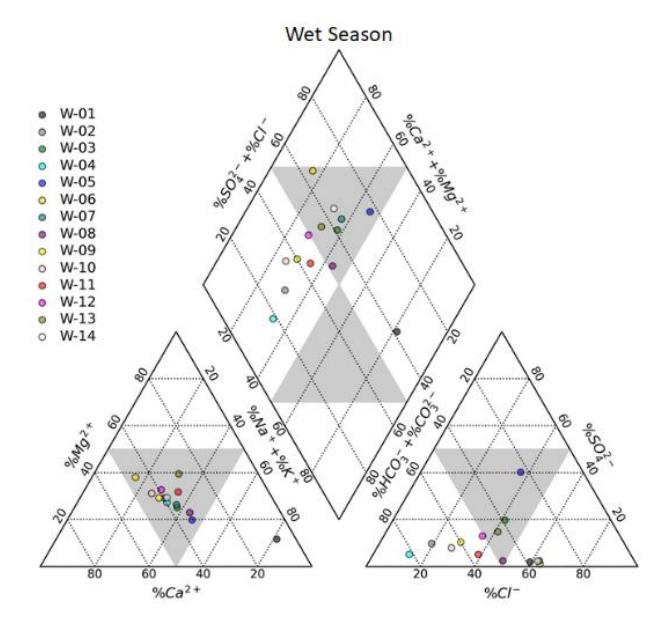
Piper diagram for the wet season. Sample W-01 plots as a Na–Cl type, while the other samples fall within the mixed Ca–Mg–Cl and Ca–Mg–HCO₃ types.
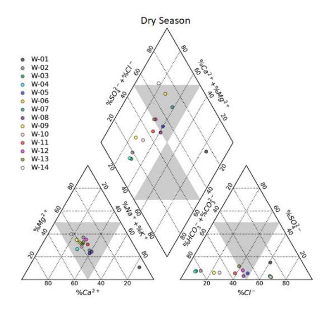
Piper diagram for the dry season. Sample W-01 plots as a Na–Cl type, while the other samples fall within the mixed Ca–Mg–Cl and Ca–Mg–HCO₃ types.
Hydrogeochemical Process
Based on the Gibbs diagrams for the wet season (Figure 9.a) and dry season (Figure 9.b), the hydrogeochemical processes indicate that the chemical characteristics of the water in the leachate well area (W-02)—a saline zone cannot be explained solely by natural processes. Additional sources of Na⁺ and Cl⁻ are required to account for the observed chemistry.
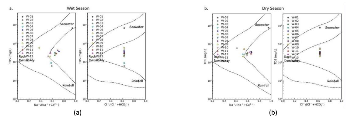
Gibbs diagram for the wet season (a) and dry season (b).
Water–rock interactions suggest that groundwater chemistry in the research area is strongly influenced by the weathering of silicate rocks. In hard rock aquifers, silicate weathering is one of the primary geochemical processes governing groundwater ionic composition (Kana et al., 2022). The interaction between groundwater and aquifer minerals significantly shapes groundwater chemistry. As tuff and volcanic breccia are the dominant lithologies in the research area, silicate minerals serve as the main contributors to mineralization. Petrographic analysis shows that these rocks primarily consist of quartz, feldspar, plagioclase, ash/lithium (in tuff), and opaque minerals (in volcanic breccia). Weathering of these minerals releases ions that dissolve into groundwater during percolation (Kana et al., 2022).
HCO₃⁻ can form when carbonic acid dissolves silicate minerals in the local rock formations (Tesoriero et al., 2004), the general reaction is:
(Cations) silicates + H2CO3 = H4SiO4 + HCO3 + cations + solid products (mostly clay minerals)
The presence of silicate minerals is further confirmed by the Gaillardet diagrams for the wet season (Figure 10(a)) and the dry season (Figure 10 (b)), both of which show consistent indications of silicate weathering. This also supports the conclusion that the HCO₃⁻ originates solely from rainwater-derived carbonic acid rather than from carbonate minerals in the sampled wells.
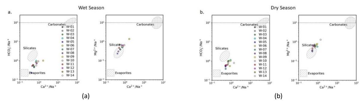
Gaillardet diagram for the wet season (a) and dry season (b).
Discussion
The main objective of this paper is to present an integrated geophysical and geochemical methodology for landfill leachate investigation to assess the temporal physical and chemical degradation of near-surface geological structures and water bodies in the Bakung landfill. This section discusses the impacts of landfill operations on surface water and groundwater environments by analyzing water in near-ground formations. To meet the stated objectives, two periods— October–November 2021 (wet season) and July 2022 (dry season)—were selected to conduct geophysical surveys, assess water quality, and observe environmental changes around the landfill.
Geoelectrical Analysis and Their Implications for Contaminants
The geoelectrical resistivity (VES and ERT) results show that the Bakung landfill exhibits both high and low resistivity values across different zones. Low resistivity values indicate leachate, as leachate with high ion concentrations facilitates the passage of electric current (Aromolaran et al., 2019). These low resistivity zones reflect leachate infiltration from the dumpsite. Higher resistivity values (62–153 Ωm) occur in the upstream section (TSD-1, TSD-2, and TSD-3), whereas the downstream section (TSD-5) displays much lower resistivity (24 Ωm), indicating the influence of leachate movement on tailings around the landfill site. The aquifer's protection capacity is categorized as poor, suggesting vulnerability to contamination. Many VES points show low protection capacity, indicating a high risk of contamination from the surface (Niaz et al., 2023; Khan et al., 2024).
Time-lapse ERT inversions for all surveys (Figure 6) were performed to interpret changes in resistivity. The number of iterations was set to five. RMS Error values for the initial model (wet season) were 4.6%, 11.9%, 11.7%, 11.1%, and 4.9% for ERT-1, ERT-2, ERT-3, ERT-4, and ERT-5, respectively, and these changed to 10.8%, 13.9%, 22.2%, 4.6%, and 8.1% in the final model (dry season). The initial model was produced by applying a single resistivity value—calculated from the average of measured resistivity values—to all computational areas. Zones displaying increased resistivity can be interpreted as leachate-contaminated areas, as the replacement of leachate-rich fluids with groundwater results in higher resistivity; groundwater typically has higher resistivity than leachate-rich fluids.
Interpretation of Fluid Flow Paths Based on Soil Texture
The ERT results were correlated with locations around the water wells to determine the flow paths of leachate migration (Figure 11). The upstream area at the base of the hill corresponds to ERT-3, where no leachate is present. ERT-1 is situated within the Bakung landfill and near the black-water pond, ERT-2 is located in the middle of the landfill, and ERT-4 lies downstream near the leachate pond. The leachate flow from ERT-2 toward ERT-1 and ERT-4 is shown in Figure 11(a).
Figure 11(b) presents the ERT-1 cross-section in relation to water well W3. Well W3 is a drilled well approximately 40 m deep and is identified as uncontaminated based on chemical and physical measurements (Table 2). The ERT-1 crosssection shows that W3 exhibits high resistivity values, indicating the absence of leachate. In ERT-1, leachate migration moves from high-resistivity anomalies toward low-resistivity anomalies, but W3 is not intersected by the leachate pathway.
Figure 11(c) shows the ERT-4 cross-section compared to the leachate river (W1) and nearby water wells (W14 and W6). The leachate pond and residential areas are located near the Bakung landfill, downstream of the ERT-4 line. Wells W14 and W6 were drilled to depths of approximately 40 m (W14) and 30 m (W6). Based on physical and chemical parameters (Table 2), the leachate river W1 and water well W14 are considered contaminated due to their high TDS values. Water well W6 is not considered contaminated, as its TDS value is around 445 mg/L—below the 500 mg/L threshold typically used to indicate contamination.
According to the Piper diagram (Figures 7 and 8), W1 falls within the NaCl water type, whereas W14 and W6 plot within the Ca–Mg–Cl water type, reflecting ion exchange involving Ca–Mg–HCO₃ and Na–Cl. Interpretation of the ERT-4 crosssection indicates the presence of leachate in W1, W14, and W6. Leachate migration in ERT-4 also moves from highresistivity anomalies toward low-resistivity anomalies. Wells W1, W14, and W6 represent leachate plumes, and the leachate originates from the ERT-1 and ERT-2 lines at the Bakung landfill source.
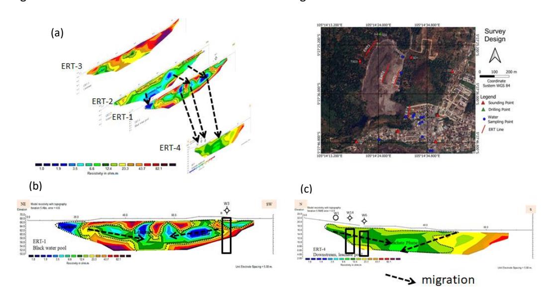
Leachate migration pathway: (a) leachate migration from ERT-2 to ERT-1 and ERT-4; (b) leachate migration in ERT-1; (c) leachate migration in ERT-4.
Analysis of Precipitation Effect
In this paper, profiles were obtained from two data subsets collected during two seasons: the rainy and dry seasons (Figure 6). Time-lapse resistivity measurements were conducted from October to November 2021 (rainy season) and in July 2022 (dry season). According to data from the Meteorology, Climatology, and Geophysics Agency (BMKG) (Figure 2), total rainfall reached 10.3 mm in October 2021, 16.25 mm in November, and 6.34 mm in July 2022.
In the time-lapse resistivity inversion results (Figure 6), the conductive zone extends continuously from the northern to the southern part of the survey area. This conductive zone expands near the surface after the onset of the rainy season. Rainfall increases near-surface saturation, producing a wider low-resistivity zone compared to the pre-rain conditions. Conductive anomalies may also emerge in conductive subsurface media, zones with high moisture content, or areas affected by contamination.
Contaminated zones were identified by observing resistivity changes at locations where contaminant leakage—such as leachate—occurs. Interpretation of resistivity values must differentiate between pre- and post-rainfall conditions, considering the characteristics of both rainfall and leachate. Figure 12 illustrates resistivity variations during the rainy and dry seasons. These variations were examined at depths of 2, 4, and 6 meters. The average ratio of resistivity changes between the dry and rainy seasons was approximately 17.5%.
Leachate contamination may gradually contribute to groundwater pollution over time, posing a significant future risk to communities surrounding the Bakung landfill.
Changes in resistivity values during the wet and dry seasons observed along a 40-meter ERT line at depths of 2, 4, and 6 meters.
Analysis of the Effect of Chlorine on Resistivity Values
A high concentration of Cl⁻ ions is a key indicator of environmentally harmful leachate (Akpan et al., 2018). Based on the Cl⁻ distribution map around the Bakung landfill well points (Figure 13), leachate is the primary source of the elevated Cl⁻ concentration (34 ppm) observed downstream at W-01. A decreasing Cl⁻ gradient is present moving away from the landfill. Because Cl⁻ behaves conservatively in groundwater, dilution is the dominant attenuation mechanism. As distance increases, the mixture of contaminated groundwater and recharge through the vadose zone combines with uncontaminated groundwater, reducing the influence of leachate (Grisey and Aleya, 2016).
Certain chlorinated compounds can be toxic or carcinogenic. Chlorinated solvents, in particular, are prone to natural attenuation. Natural attenuation involves physical, chemical, or biological processes that reduce the mass, toxicity, mobility, or volume of contaminants without engineered intervention. However, hydrologic and geochemical conditions that support attenuation may change over time, allowing previously immobilized contaminants to become remobilized. As such, natural attenuation is generally integrated into long-term management strategies for chlorinated solvents in groundwater.
A comparison between the apparent iso-resistivity map and the Cl⁻ distribution map (Figure 13) shows that low resistivity values correspond to high Cl⁻ concentrations. Leachate plumes are typically present in relatively small quantities due to natural processes that reduce contaminant concentrations with increasing distance from the source. The observed decline in Cl⁻ concentration along the groundwater flow path indicates natural attenuation, which is consistent with the corresponding increase in specific resistivity.
Water sample analysis further indicates that electrical conductivity (EC) is influenced by Cl⁻ concentration. Figure 14.a shows a poor correlation (0.1168) between Cl⁻ and EC across all water samples, caused by the leachate outlier. When the leachate sample is excluded, the correlation improves substantially to 0.9 (Figure 14.b), indicating a direct relationship in which higher Cl⁻ concentrations result in higher EC values. Similarly, Figures 14.c and 14.d show strong correlations (greater than 0.8) between Cl⁻ and salt content, both with and without the leachate sample. Because Cl⁻ is a major component of salts such as NaCl, increasing Cl⁻ concentrations elevate salt content, which in turn increases EC. Thus, higher Cl⁻ values, higher salt concentrations, and higher EC values are directly associated.
Based on the hydrogeochemical and geoelectrical resistivity findings, the Bakung landfill clearly exhibits leachate that adversely affects the local environment, particularly downstream areas located near residential communities. Geophysical data show that leachate has continued to migrate through the subsurface layers, with long-term leaching into groundwater occurring for more than two decades. Consequently, groundwater extraction around the landfill should be discontinued to prevent further migration of leachate within the subsurface.
The results also indicate that leachate contamination remains concentrated around the immediate vicinity of the Bakung landfill. To prevent additional contamination of soil and groundwater aquifers in the study area, the implementation of a properly engineered landfill system and public awareness initiatives to discourage uncontrolled waste disposal are necessary. Ensuring compliance with landfill management regulations and providing suitable engineered waste facilities remain critical responsibilities of the government.
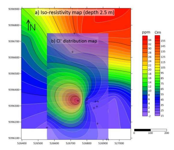
Comparison of the iso-resistivity map at a depth of 2.5 meters (a) and the Cl⁻ distribution map (b).
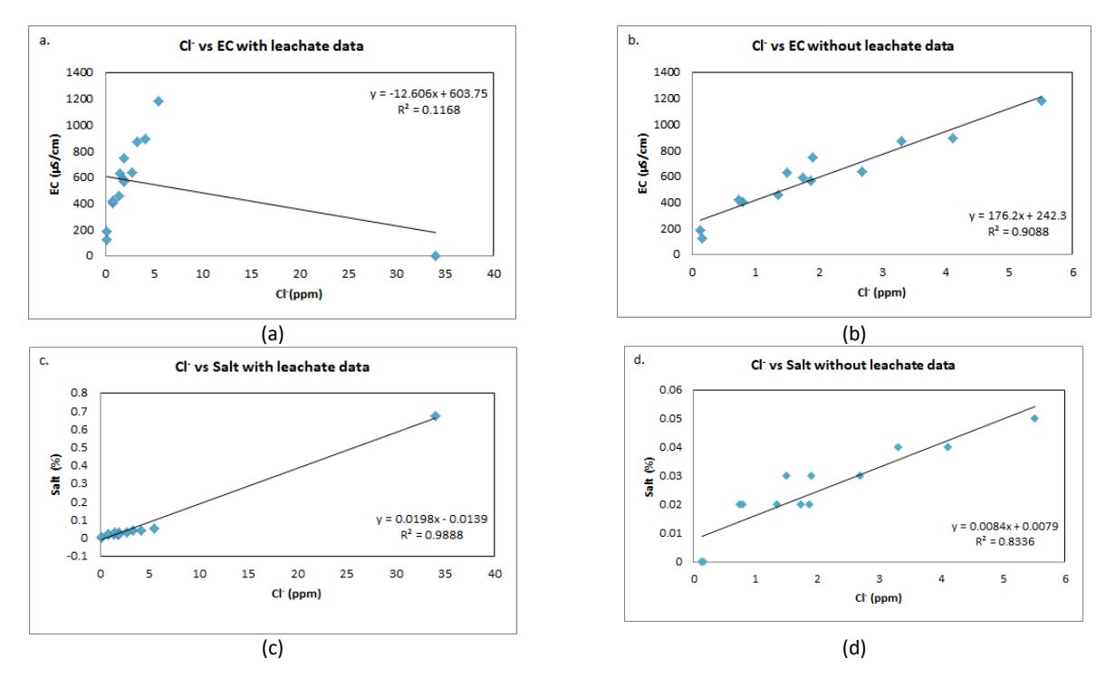
Relationship between Cl⁻ and EC in all water samples (a), Cl⁻ and EC without the leachate sample (b), Cl⁻ and salt concentration in all water samples (c), and Cl⁻ and salt concentration without the leachate sample (d).
Conclusion
An integrated approach combining hydrogeochemical surveys and electrical imaging methods was employed to investigate groundwater contamination near the Bakung landfill. The Bakung landfill exhibits resistivity values of less than 40 Ωm, which are interpreted as tuff based on the 1D resistivity model, while rocks with resistivity values greater than 40 Ωm are identified as volcanic breccia. At ERT-1, located around the landfill and near the black-water pond site, the top layer shows resistivity values of 20–200 Ωm, representing a saturated waste zone consistent with the 2D interpretation along the Bakung landfill profile. At ERT-2, situated within the landfill, the top mixed leachate–waste zone has resistivity values of 13–35 Ωm. At ERT-3, located west of the landfill, the upper soil layer exhibits resistivity values of 20–200 Ωm and corresponds to soft, clay-like material. At the leachate pond and downstream area (ERT-4), the leachate plume zone appears on the left section with resistivity values below 15 Ωm, indicating likely downward migration from the upper layer.
Hydrogeochemical facies interpretation using the Piper diagram identifies three facies: the Ca-HCO₃ facies, representing uncontaminated freshwater affected by water–rock interaction; the NaCl facies in borehole W-01, indicating leachatebearing groundwater enriched with dissolved salts; and the mixed Ca-Mg-Cl facies, representing the early stage of geochemical evolution driven by mixing between catchment water and local precipitation and/or ion exchange between Ca-Mg-HCO₃ and Na-Cl water types. Hydrogeochemical processes also indicate silicate weathering, while HCO₃ originates solely from rainwater, as carbonate minerals are absent in the well samples.
The relationship between geoelectrical resistivity and hydrogeochemical conditions is demonstrated through Cl⁻, which acts as a conservative tracer for water and ion flux. Elevated Cl⁻ concentrations in leachate indicate potential environmental harm. Although natural attenuation processes—such as dilution, absorption, ion exchange, precipitation, redox reactions, and degradation—reduce contaminant concentrations with increasing distance from the source, resistivity generally increases as Cl⁻ concentrations decrease along the flow direction.
The findings indicate that contaminants from leachate have not yet infiltrated the groundwater, although geophysical evidence shows that leachate plume migration within the soil continues. Therefore, the Bakung landfill should be closed for reclamation to reduce further leachate percolation that may lead to groundwater contamination in the near future. Groundwater extraction around the landfill should also be discontinued to prevent subsurface leachate plume expansion. The results highlight the need for proactive monitoring and remediation to mitigate the potential risks posed by landfills to groundwater systems.
A limitation of this study is its reliance solely on resistivity and hydrogeochemical data to evaluate seasonal changes. Further studies linking resistivity, leachate concentration, and fluid properties are recommended to develop a hydrogeological model capable of predicting leachate and contaminant distribution over time. Developing contamination modeling to illustrate leachate transport mechanisms and predict groundwater quality is also recommended.
Acknowledgment
This research was financially supported by ITERA (Institut Teknologi Sumatera) and DIKTI (Directorate General of Higher Education of Indonesia).
Compliance with ethics guidelines
The authors declare they have no conflict of interest or financial conflicts to disclose.
This article contains no studies with human or animal subjects performed by the authors.