
Introduction
The ongoing research and development of science and technology towards the development of intelligent transportation systems (IT) solutions, such as autonomous vehicles (AV), is expected to significantly reduce traffic accidents (Amirkhani et al., 2024; Maddiralla et al., 2024). Several studies have focused on employing optimal algorithms to address the challenges of vehicle recognition, road mapping, and automatic vehicle control (Souza et al., 2024; Qiu et al., 2024). Evaluation solutions aimed at improving the performance of advanced driver assistance systems (ADAS) models include the use of LiDAR and cameras in bad weather conditions (Farkh et al., 2023; Neumann, 2024; Elassy et al., 2024); some systems focus on developing positioning sensors to determine the location of the vehicle (Elassy et al., 2024; Vivacqua et al., 2017; Wang, 2018). Autonomous electric vehicles are often deployed to assist humans in performing complex tasks, including modern taxis, military, industrial, search and rescue operations, and modern agriculture (Zhang et al., 2023). Additionally, the use of cameras for road detection and advanced algorithms to control the electric vehicle (Yao et al., 2019; Pitropov et al., 2021; Guo et al., 2021) to follow the available line is analyzed. Notably, lines, such as black road markings on the white stage setting, can be pre-set and easily recognized. Furthermore, the cost is minimized by using simple image processing algorithms and the proposed Raspberry Pi, along with the NVIDIA Jetson Nano card hardware, to control the electric vehicle's steering wheel moving in the permitted lane, as mentioned in (Wang et al., 2018). To identify, track, and predict the approach of the lane (Jang et al., 2023; Liu et al., 2021), the author (Sultana et al., 2023) has presented 3 technological solutions, including comprehensive intensity threshold range (CITR), angle-based geometric constraint (AGC), length-based geometric constraint (LGC), and range of horizontal lane position (RHLP). In particular, these studies present a complete overview of lane detection methods (Maddiralla et al., 2024; Zakaria et al., 2023; Bhargava et al., 2024).
This study evaluates the effectiveness of the currently employed methods, emphasizing improving accuracy and speed performance, as well as testing and developing the system (Gajjar et al., 2023) to operate efficiently under different harsh conditions during lane detection (Surono et al., 2022; Abdolrasol et al., 2023). This paper aims to develop a selfdriving car model that integrates a camera (Farkh et al., 2023; Elassy et al., 2024) for line detection and exploits the Particle Swarm Optimization (PSO) (Sathish Kumar et al., 2023; Siddikov et al., 2024) and the Takagi–Sugeno Fuzzy algorithm (Jang et al., 2023; Swethamarai et al., 2022; Ntakolia et al., 2023; Regaya et al., 2021; Brahmi et al., 2025) for automatic control of the vehicle's direction (Swethamarai et al., 2022) and a controller (PID) consisting of proportional stages combined with integral and derivative stages to regulate the moving speed and turning direction of an electric vehicle (Ntakolia et al., 2023; Oladipo et al., 2023; Dash et al., 2023). In the experimental process of the road tracking problem for self-driving electric vehicles, the following three control algorithms, Fuzzy-PID, PSO-PID, and Fuzzy-PSO, were implemented and compared. Here, the input data was collected from the camera image processing system under guided path conditions, which include rotation angles of 0°, 10°, 20°, 30°, 40° and a curve with a radius of 5 m. According to the results, the Fuzzy-PSO controller, integrating the fuzzy system and the particle swarm optimization algorithm, achieved the highest control performance. Compared to the fuzzy-PID and PSO-PID methods evaluated under the same conditions, this integration enables the control system to respond more flexibly, stably, and accurately in tracking the trajectory. Notably, integrating the fuzzy algorithm with the traditional PID controller and the optimization capability of PSO has enhanced control efficiency, improved the ability to process feedback signals from the camera, and increased the flexibility of the system. Particularly, the fuzzy controller enables the vehicle to respond quickly to changes in actual driving conditions. Despite achieving relatively good control efficiency, the control response of the Fuzzy-PID algorithm is limited in certain input value ranges, causing delays in the state transition and affecting the vehicle's response speed in the desired direction.
Automated electric vehicle tracking road.
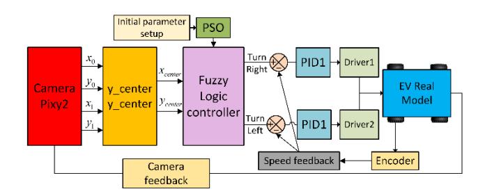
In this study, the electric vehicle system integrates several modern sensors and devices, including Lidar, GPS, rear camera, inertial and odometry sensors, radar sensors, and video camera systems, along with a central computer that performs processing and decision-making tasks. Lidar provides distance information and generates 3D maps of the surrounding environment, whereas GPS supports high-precision global positioning. The lanes, obstacles, and other vehicles in the traffic environment are detected using cameras and radar sensors. The central computer integrates data from various sensors and executes control, navigation, and decision-making algorithms in real time. Notably, the synchronous integration of hardware and software enables the accurate and safe movement of the vehicle and adaptation to various operating conditions. Figure 1 presents an overview model of an autonomous vehicle system, underscoring the key role of trajectory-tracking technology, which is extensively used in autonomous vehicle control platforms. Additionally, the camera system plays a primary role in this study in identifying and tracking guidance lines, thus enabling the vehicle to maintain accurate movement direction along the predetermined route.
Research Contributions and Novelty: First, unlike many works that focus solely on simulation environments, this study is implemented on an actual miniature self-driving car platform equipped with a Pixy2 vision system. Second, the proposed approach employs PSO not for tuning PID parameters or fuzzy memberships in general, but specifically to optimize the output constants of the Takagi–Sugeno FLC, which directly influence steering control. Third, this study adopts ITAE as the optimization criterion, which is particularly well-suited for trajectory tracking tasks. Finally, the controller was validated through 500 independent experiments under diverse road conditions, providing strong evidence of robustness.
Materials and Methods
Image Processing and Fuzzy Algorithms for Autonomous Vehicle Control
The Pixy2 camera captures the image data, which is sent to the microcontroller to display the value in vector form. Figure 2 displays the captured camera data when the black line is detected. The coordinates sent to the microcontroller include the main parameters: coordinates (m_x0, m_y0) representing the vector tail values on the camera frame and coordinates (m_x1, m_y1) representing the vector head values on the camera frame.
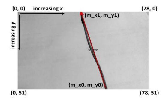
Data from the Pixy2 camera is sent to the microcontroller.
The data in Figure 3 starts with the camera image, which is analyzed to obtain information including vector values (x0, y0), (x1, y1), the border, and the center of the frame
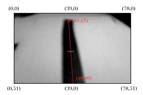
Vector image captured by Pixy2 Camera on a straight line (0 degrees).
The construction of the algorithm begins by determining the central positions of the line and the frame from the image. The center of the frame is fixed at (39, 25.5), while the center of the line (, ) is calculated using formula (1). These values form the basis for designing a Takagi–Sugeno fuzzy controller to control the automatic direction and a PID controller to regulate the driving speed of the electric vehicle.
\[x_{center} = \left(\frac{x_0 + x_1}{2}\right)\] \[y_{center} = \left(\frac{y_0 + y_1}{2}\right)\] (1)
Where: 0 : end value of line close to x-axis; 1 : start value of line close to x-axis; 0 : end value of line close to y-axis; 1 : start value of line close to y-axis.
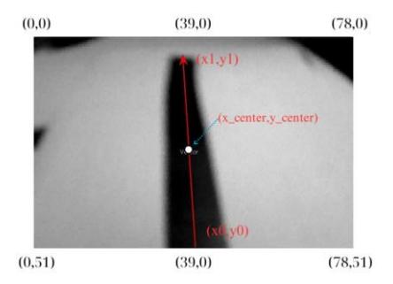
The two left motors reduce the driver speed of the remaining motor by including the driver of the electric vehicle. Thus, the electric car moves towards the black line in Figure 4. This is the basis for designing a self-driving car system using fuzzy algorithms.
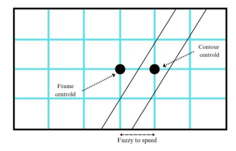
Image of the center of the frame and the center of the line in the camera image.
Fuzzy and PID Controller Design for the System
The value range of is (0; 78) pixels, and that of is (0; 51) pixels. When the values of and are both at the midpoint (39; 25.5) pixels, they coincide with the center of the frame. The center of the electric car aligns with the middle of the line. When the value of (, ) falls to the left or right of the middle of the frame, the car turns right or left at varying speeds. The speed can be fast or slow, depending on the value range of this vector.
Vector image captured by Pixy2 camera on a straight line (0 degrees).
Figure 5 displays the direction and value of the head and tail of the vector when a straight line is detected. These signals from the camera are transmitted to the microcontroller through the Fuzzy controller, allowing the electric vehicle to run straight. Table 1 (Luo et al., 2023; Abdelghany et al., 2023) presents the definition and description of the input fuzzy language variable of the fuzzy controller. Table 2 presents the construction of 25 fuzzy rules for the controller to serve the control process. It indicates the output of the denazification Takagi-Sugeno fuzzy operation to control the electric car to turn left and turn right.
| Variables | Membership Functions | Range (pixels) | Membership function type |
|---|---|---|---|
| TNX | [0; 26] | Trapezoidal | |
| TVX | [13; 39] | Triangular | |
| 𝑥𝑐𝑒𝑛𝑡𝑒𝑟 | GX | [26; 52] | Triangular |
| PVX | [39; 65] | Triangular | |
| PNX | [52; 78] | Trapezoidal | |
| TNY | [0; 17] | Trapezoidal | |
| TVY | [8.5; 25.5] | Triangular | |
| 𝑦𝑐𝑒𝑛𝑡𝑒𝑟 | GY | [17; 34] | Triangular |
| PVY | [25.5; 42.5] | Triangular | |
| PNY | [34; 51] | Trapezoidal |
Table 1 The variables input for the Fuzzy Logic system.
Figure 6 shows the Membership function plots of the two inputs used for the Takagi-Sugeno fuzzy system. (Where: TNX: Left much X; TVX: Left medium X; GX: Middle X; PVX: Right medium X; PNX: Right much X; TNY: Left much Y; TVY: Left medium Y; GY: Middle Y; PVY: Right medium Y; PNY: Right much Y).
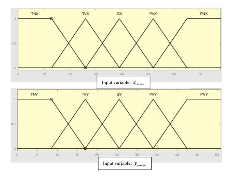
Input membership function of two fuzzy inference systems.
| Table 2 | Fuzzy control rules of the Takagi-Sugeno fuzzy algorithm for autonomous vehicles. |
|---|
| 𝒙𝒄𝒆𝒏𝒕𝒆𝒓 | 𝒚𝒄𝒆𝒏𝒕𝒆𝒓 | Turn Left | Turn Right | No. | 𝒙𝒄𝒆𝒏𝒕𝒆𝒓 | 𝒚𝒄𝒆𝒏𝒕𝒆𝒓 | Turn Left | Turn Right |
|---|---|---|---|---|---|---|---|---|
| TNX | TNY | TC | PNN | 16 | PVX | TNY | TNN | PC |
| TNX | TVY | TV | PNN | 17 | PVX | TVY | TNN | PV |
| TNX | GY | BT | PN | 18 | PVX | GY | TN | BT |
| TNX | PVY | TV | PNN | 19 | PVX | PVY | TNN | PV |
| TNX | PNY | TNN | PC | 20 | PVX | PNY | TC | PNN |
| TVX | TNY | TC | PNN | 21 | PNX | TNY | TNN | PC |
| TVX | TVY | TV | PNN | 22 | PNX | TVY | TNN | PV |
| TVX | GY | BT | PN | 23 | PNX | GY | TN | BT |
| TVX | PVY | TV | PNN | 24 | PNX | PVY | TNN | PV |
| TVX | PNY | TNN | PC | 25 | PNX | PNY | TC | PNN |
| GX | TNY | BT | BT | |||||
| GX | TVY | BT | BT | |||||
| GX | GY | BT | BT | |||||
| GX | PVY | BT | BT | |||||
| GX | PNY | BT | BT |
Where: TNX: Left high X; TVX: Left medium X; GX: Center X; PVX: Right medium X; PNX: Right high X; TNY: Left high Y; TVY: Left medium Y; GY: Center Y; PVY: Right medium Y; PNY: Right high Y; TC: Slow left; TV: Medium left; BT: Normal; TN: Fast left; TNN: Fastest left; PC: Slow right; PV: Moderate right; PN: Fast right; PNN: Fastest right.
Although there are various methods for denazification, this paper adopts the weighted average method due to its extensive use and high accuracy in making control decisions compared to other methods. The weighted average method is calculated using the following formula:
\[x *= \frac{\sum u_X(x).x}{\sum u_X(x)} \tag{2}\]
Where: ∗ is the decoded output, () is the aggregate membership function and is the output variable.
Table 3 The left wheel speed linguistic output variables of the Takagi-Sugeno fuzzy system.
| Variable name | Membership function name | Range (m/s) | Membership function type |
|---|---|---|---|
| TC | 0 | Constant | |
| TVA | 1 | Constant | |
| Turn Left | BT | 2 | Constant |
| TN | 3 | Constant | |
| LNN | 4 | Constant |
Where: TC: Left slow; TVA: Left moderate; BT: Normal; TN: Left fast; LNN: Left fastest.
| Variable name | Membership function name | Range (m/s) | Membership function type |
|---|---|---|---|
| PC | 0 | Constant | |
| PV | 1 | Constant | |
| Turn Right | ВТ | 2 | Constant |
| PN | 3 | Constant | |
| PNN | 4 | Constant |
Table 4 Right wheel speed language output variables of the Takagi-Sugeno fuzzy system.
Where: PC: Slow right; PV: Moderate right; BT: Normal; PN: Fast right; PNN: Fastest right.
Adjusting the PID Speed of the Motors
The PID speed of the motors was adjusted by initially setting a constant proportional value of 0.101, which was significantly tuned until the electric vehicle exceeded its limit and started to oscillate continuously. At that time, the value of the constant proportionality \((K_u)\) was obtained along with the oscillation period \(T_n\), which was used to calculate \(K_p\). To adjust the parameters \(K_i\) and \(K_d\), \(K_u\) and \(T_u\) were used as instructed in Table 5.
| Adjustable parameter set | |||
|---|---|---|---|
| Rules | \(K_p\) | \(K_i\) | \(K_d\) |
| No overshoot | \(0.2K_u\) | \(2K_p/T_u\) | \(K_pT_u/3\) |
| Some overshoot | \(0.33K_{u}\) | \(2K_p/T_u\) | \(K_pT_u/3\) |
| Classic Ziegler–Nichols | \(0.6K_{u}\) | \(2K_p/T_u\) | \(K_pT_u/8\) |
| Pessen Integral Rule | \(0.7K_{u}\) | \(2.5K_p/T_u\) | \(0.15K_pT_u\) |
Table 5 PID control adjustment parameters.
Furthermore, the inverse Euler numerical integration method was used to convert the control algorithm equation of the PID controller into a discrete form, as represented below:
\[u(kT) = K_p e(kT) + K_i T \sum_{k=0}^{n} e(kT) + K_d \frac{e(kT) - e(kT - T)}{T}\] (3)
Design of Fuzzy-PID, Fuzzy-PSO, and PSO-PID Controllers
The result of fuzzy inference is the transformation of conventional input data into interpretable data results obtained through the processes of fuzzification and defuzzification, as well as fuzzy rules and membership functions. Notably, the knowledge base consists of IF-THEN rules that result in an algorithm for determining the action or output required to complete the desired control task (El Hammedi et al., 2023; Hieu et al., 2021). The initial proportional parameter values of the fuzzy controller are calculated using the adjusted gain values (\(K_p\), \(K_i\) and \(K_d\)) of the PID controller. However, the proportional parameter values should be adjusted to improve the controller performance (Ibrahim et al., 2024). As detailed in Figure 7, the autonomous electric car is controlled during the experiment using the Fuzzy-PID algorithm, with the camera enabling tracking.
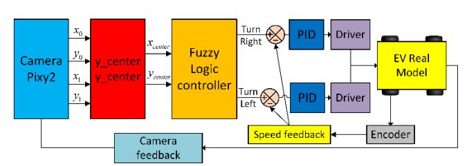
Figure 7 Autonomous Electric Vehicle Control System with Fuzzy-PID algorithm.
Design of Fuzzy-PSO Controller
To optimize a problem using heuristic methods, it is vital to establish a fitness function (4). One approach to assessing the effectiveness of a solution is by evaluating its fitness function (Li et al., 2023). Various fitness functions have been employed to adjust the parameters of PID controllers. Some of these functions are based on metrics like rise time (\(T_{rise}\)), steady-state error (\(e_{SSE}\)), overshoot (\(O_{sh}\)), and settling time (\(T_{so}\)) of the motor output, while others are based on the integral of the error. In this study, the integral time absolute error (ITAE) function is used as our fitness function. As demonstrated in the equation, the standard form of the PID controller optimization problem typically employs ITAE as the objective function. The main purpose is to minimize the function to obtain the optimal solution for the following parameters: \(K_P\), \(K_I\), and \(K_D\).
\[ITAE = \int_0^{T_{ES}} t|e(t)| dt \tag{4}\]
Subject to \(L_l \leq K_P\), \(K_l\), \(K_D \leq U_l\). Where t represents the simulation time, ranging from 0 to \(T_{ES}\), e(t) denotes the error, calculated as the disparity between the set reference speed \(\omega_{ref}(t)\) and the motor speed \(\omega(t)\). \(L_l\) and \(U_l\) designate the lower and upper limits, respectively.
Notably, the algorithm mimics the collective behavior observed by groups of animals such as birds and fish (Morales-Castañeda et al., 2023; Hannan et al., 2023). The algorithm efficiently navigates complex search spaces by leveraging the intelligence of the group. Based on both individual and group performance, each member of the swarm dynamically adjusts its position and velocity, converging cooperatively toward the best solution. This approach reflects the coordinated movements of foraging organisms, enabling rapid convergence to optimal solutions. The algorithm works on the principle of leveraging the cooperative intelligence of a population of particles to explore complex search spaces (Wang, 2023; Xia et al., 2022; Mohamed et al., 2025).
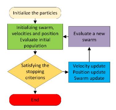
Figure 8 The chart steps of PSO used to control electric vehicles.
Figure 8 presents a flow diagram illustrating the different steps of this swarm optimization algorithm. A random population of members is generated initially, with each member representing a possible solution characterized by locations and velocity vectors. As the members traverse the d-dimensional foraging space in the habitat, they are drawn towards optimal solutions resolved by themselves and their neighbors. It must be noted that each member records its position and the best solution it has encountered so far. Based on the individual's experience and the collective knowledge of the swarm, the algorithm updates the position and velocity of the particle at each step. Thus, through the dynamic interaction of the foraging exploration and exploitation of the swarm, PSO efficiently converges towards promising solutions in the search space.
Each member of the swarm in the PSO algorithm is incorrectly represented by a d-dimensional vector, indexed as \(X_i(t)\) with \(i=1,2,\ldots,m\). Here, the \(i_{th}\) particle occupies a position \(X_i(t)=[x_{i1}(t),x_{i2}(t),\ldots,x_{id}(t)]\) in the search space. Additionally, the velocity of each particle, commonly referred to as the 'flight' velocity, is represented as a d-dimensional vector denoted by \(V_i(t)=[v_{i1}(t),v_{i2}(t),\ldots,v_{id}(t)]\) (Yao et al., 2024). Furthermore, each particle maintains a record of its optimal position and is denoted by \(P_i(t)=[p_{i1}(t),p_{i2}(t),\ldots,p_{id}(t)]\). The peak points of the best particles detected by the algorithm till time t are encapsulated in \(G_i(t)=[g_{i1}(t),g_{i2}(t),\ldots,g_{id}(t)]\). Notably, the PSO algorithm is guided by a set of equations that iteratively update the positions and velocities of the swarm members. The resulting results are given by equations (5) and (6).
\[V_{id}(t+1) = W \times v_{id}(t) + C_1 \times Rand_1(\cdot) \times (P_{id}(t) - X_{id}(t)) + C_2 \times Rand_2(\cdot) \times (P_{gd}(t) - X_{id}(t))\] \[X_{id}(t+1) = X_{id}(t) + V_{id}(t)\] (6)
Where: \(X_{id}(t)\): the position of particle i with objective value fitness; \(V_{id}(t)\): velocity of particle i; \(C_1\) and \(C_2\) are learning rates; W: inertia weight; \(Rand_1(\cdot)\), \(Rand_2(\cdot)\) are uniformly distributed random numbers between [0,1]; \(P_{gd}(t)\): the global best position; \(P_{id}(t)\): the best historical position of particle i itself (local best position or its experience).
\[P_{id}(t+1) = \begin{cases} p_{id}(t)iff(X_{id}(t+1)) \ge f(p_{id}(t)) \\ X_{id}(t+1)iff(X_{id}(t+1)) < f(p_{id}(t)) \end{cases}\](7)
\[p_{gd}(t+1) = \arg\min f(p_{id}(t+1)), 1 \le i \le d\] (8)
The best global position −() is determined by considering the condition of all particles during the previous three steps. As depicted in Figures 9 and 10, the membership functions for () and ̇() are of the traditional triangular (Cao et al., 2023) form.
The quarter electric car is used to establish fuzzy rules and implement a PSO code, which is iterated 120 times to obtain precise parameters for the PID Controller (Dirik, 2022; Li et al., 2024). The upper and lower limits and are chosen as: = 0.001, and = 120.
The improved PSO algorithm is optimal with parameters: swarm size = 52 individuals; inertial weight decreases linearly over iterations , acceleration coefficient 1 = 2.9, 2 = 1.6, maximum velocity .
Autonomous electric vehicle control system with PSO-PID algorithm.
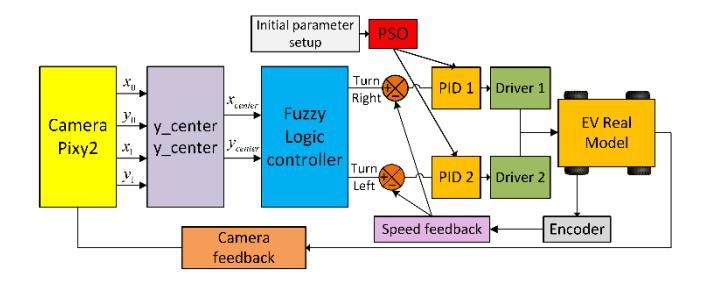
Figure 9 presents the optimum adaptive tuning parameters given for two sets of parameters 1 ,1 ,1 of the turnright vehicle controller and 2 ,2 ,2 of the turn-left vehicle controller. Moreover, in the experiment, the autonomous electric car is controlled using the PSO-PID algorithm (Хиеу & Агабубаев, 2022), with the camera enabling tracking.
Autonomous electric vehicle control system with Fuzzy-PSO algorithm.
The PSO adjusts the 5 values of the language variables [TC, TVA, BT, TN, LNN] that control the electric vehicle's right turn to minimize the output error. Simultaneously, the PSO optimizes the 5 values of the 5 language variables [PC, PV, BT, PN, PNN] that control the electric vehicle turning left to minimize output error. Figure 10 displays the autonomous electric car being guided by the camera using the Fuzzy-PSO algorithm in the experiment.
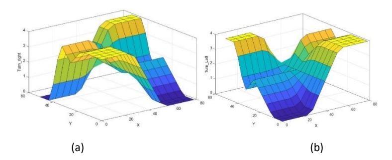
Output defuzzification of fuzzy controller electric car: (a) Turn right; (b) Turn left.
This paper presents a comparative analysis of various scenarios, including acceleration and deceleration, various rightturn and left-turn angles, and the system response using both PSO-FLC-PID and FLC-PID controllers, as illustrated in Figures 9–11.
Results
Hardware Design of Autonomous Vehicles
In this study, the central control system of an autonomous vehicle utilizes a microcontroller to flexibly process and control its operation. The Pixy2 camera, acting as a miniature computer vision model, identifies the lines and transmits data to the central microcontroller. The BTS7960 module controls the wheels to maintain correct direction and speed. For a self-driving car to operate stably and accurately, an image-processing camera system is indispensable. The Pixy2 camera features an integrated image processing system operating at a processing speed of 60 frames per second (fps) and is considered a miniature visual computer. The detection of the line and calculation of the start and end coordinates (head and tail) of the vector indicate the position of the electric car relative to the actual lane based on camera feedback. The data must be transmitted from the Pixy2 camera to the central microcontroller via the ICSP communication channel for processing and computation to ensure the car follows the correct lane.
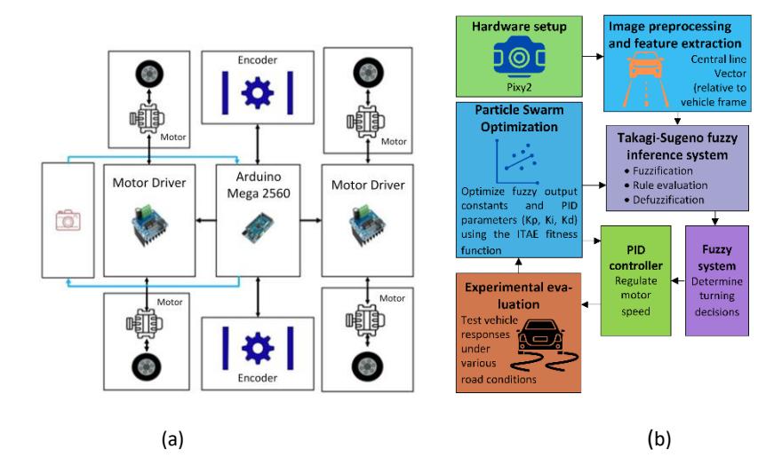
(a) Hardware connection diagram of the autonomous electric vehicle system; (b) Proposed control and optimization flowchart.
Model System Hardware for an experiment.
The microcontroller uses the central processing unit (CPU) to control the road holding speed and steering direction of the electric vehicle's wheels, to receive signals from the Pixy 2 camera, and to process fuzzy algorithms. The main processor of the board is a microcontroller chip operating at a frequency of 16 MHz and specifically utilizes four PWM pulses to control speed and steer 4 tires. The entire electric vehicle employs two H-bridge circuits to control four motors attached to four tires, enabling forward and reverse rotation, as well as variable speeds to manage the driving direction of the electric vehicle. Figure 13 displays the hardware setup. To test the research controller algorithm on real models, experiments are conducted with miniature models of self-driving electric cars.
Evaluation of Experimental Results
Next, the Takagi–Sugeno fuzzy controller was designed for the self-driving electric vehicle. Furthermore, the research team programmed the Fuzzy-PID algorithm on the microcontroller. Based on the data collected through measurements of sensors placed at the front of the electric vehicle, Figures 14 to 39 present graphs illustrating the performance on pre-set roads and the vehicle's deviation from the line at 0°, 10°, 20°, 30°, and 40° corners and circular paths. Additionally, the Fuzzy-PID, Fuzzy-PSO, and PSO-PID algorithms are used together to evaluate the PID algorithm for a more optimal control strategy. PSO optimization was performed offline with 120 iterations, and once the optimal parameters were obtained, the real-time controller ran efficiently on a microcontroller with a 16 MHz processor. Thus, the online computational overhead is minimal, and real-time feasibility is ensured. Compared to more complex optimization-based adaptive controllers, this approach balances accuracy with computational efficiency.
An electric vehicle running on a real road with a 0-degree corner.
Deviation of the electric vehicle running on the actual road with a 0-degree corner.
Figure 14 displays a graph showing the position of the electric vehicle as it follows the line guide through a 0-degree corner. The graph demonstrates that the electric vehicle operates effectively on the road with minor oscillations around the original line. Figure 15 illustrates the deviation of the vehicle on a 0-degree corner, showing that the oscillation is less than 0.015 m as the electric vehicle moves above and below the baseline.
An electric vehicle running on a real road with a 10-degree right corner.
An electric vehicle running on a real road with a 10-degree left corner.
Figures 16 and 17 illustrate the position of the electric vehicle as it moves on the line through 10-degree right and left corners. Notably, the electric car maintains a good grip on the road, with small oscillations around the original line. However, increased oscillation is observed due to inertia when the electric vehicle turns left and right.
The electric vehicle deviation on a real road with a 10-degree right corner.
Deviation of the vehicle running on the actual road with a 10-degree left corner.
Figures 18 and 19 show the deviation of the vehicle as it moves along on the actual road with a 10-degree turn, suggesting that the oscillation above and below the baseline remains small, less than 0.03 m.
The electric vehicle is running on a real road with a 20-degree right corner.
The electric vehicle is running on a real road with a 20-degree left corner.
The graphs in Figures 20 and 21 display the position of an electric car as it navigates the line through 20-degree corners. It is noted that the vehicle maintains a good grip on the road and has small oscillations around the original line. Nevertheless, the vehicle oscillates more at the corners.
Electric vehicle deviation on a real road with a 20-degree right corner.
Deviation of the actual electric vehicle running on the road with a 20-degree left corner.
As shown in Figures 22 and 23, the deviation of the actual vehicle running with a 20-degree turn indicates that the oscillations above and below the baseline are small, which is less than 0.035 m.
An electric vehicle running on a real road with a 30-degree right corner.
An electric vehicle running on the arterial road with a 30-degree corner.
The graphs in Figures 24 and 25 display the position of the electric vehicle on the line with the 30-degree corner. Here, the electric vehicle maintains a good grip on the road and has small oscillations around the original line. However, the electric vehicle oscillates more at the corners.
Vehicle deviation on a real road with a 30-degree right corner.
Deviation of the vehicle running on the actual road with a 30-degree left corner.
Figures 26 and 27 show the deviation of the vehicle navigating a 30-degree curve on the actual road, indicating that the oscillation above and below the baseline remains small (less than 0.04 m).
The electric vehicle is running on a real road with a 40-degree right corner.
The electric vehicle is running on a real road with a 40-degree left corner.
The graph in Figures 28 and 29 shows the position of the electric vehicle on the line at a 40-degree angle. The electric car has a good grip on the road and has small oscillations around the original line. Nonetheless, the electric vehicle oscillates more at the corner.
Electric vehicle deviation on a real road with a 40-degree right corner.
Deviation of the actual vehicle running on the road with a 40-degree left corner.
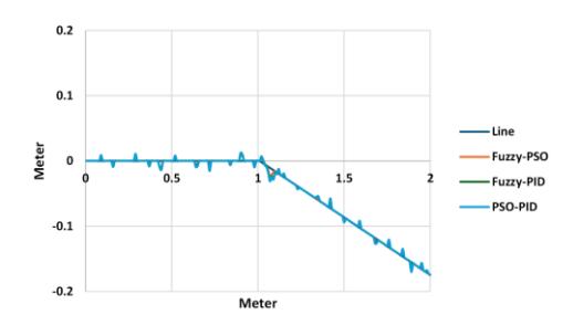
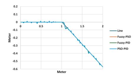
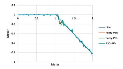
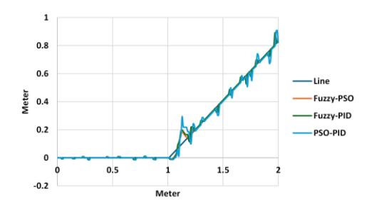
Electric vehicle is running on the real circular track.
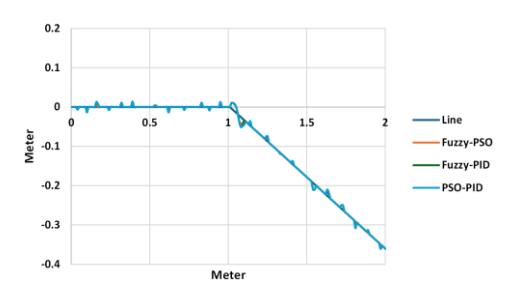
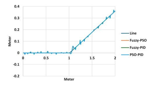
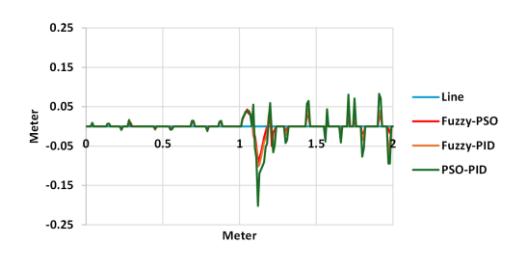
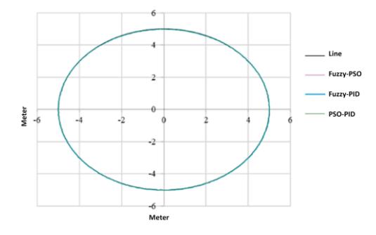
Figures 30 and 31 show the deviation of the actual vehicle during a 40-degree turn, indicating that the oscillation remains extremely small (less than 0.20 m) when the electric vehicle runs above and below the baseline. Figure 32 displays the experimental results of the self-driving electric vehicle following a circular trajectory, comparing its central gravity stability with the Fuzzy-PID, PSO-PID, and Fuzzy-PSO algorithms.
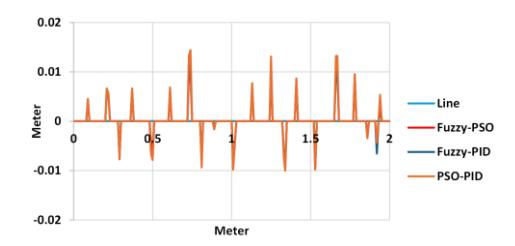
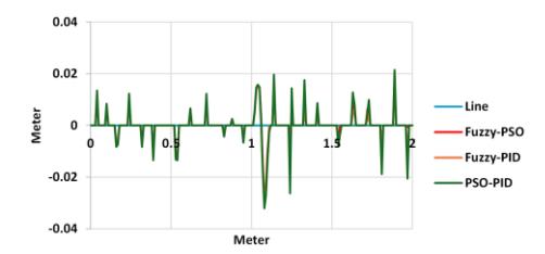
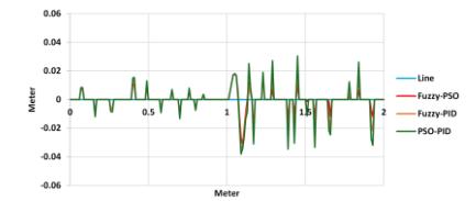
Actual deviation of an electric vehicle running on a circular track.
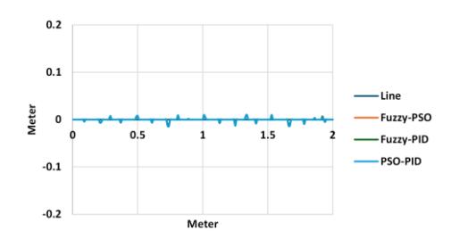
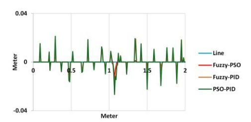
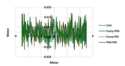
As shown in Figure 33, the deviations between the standard line and those produced by Fuzzy-PID, Fuzzy-PSO, and PSO-PID algorithms are compared when the autonomous vehicle runs on a circular track with a radius of 5 m. Thus, the fuzzy-PID control algorithm performs best due to its ability to process the fuzzy logic and respond quickly to the actual steering movement of the vehicle. Moreover, the Fuzzy-PSO algorithm yields relatively good results. Since the combination of these two algorithms makes the processing relatively slower than the Fuzzy-PID, there is a delayed steering response. Notably, the PSO-PID algorithm yields positive results, with the autonomous vehicle following the standard line. However, its drawback is that it necessitates the integration of the driver speed of the fuzzy algorithm and the processing speed of the PSO algorithm to generate control signals for the vehicle to follow the line. Furthermore, an issue with the time delay in finding the optimal PSO parameters causes deviations between the vehicle's central line and the standard line.
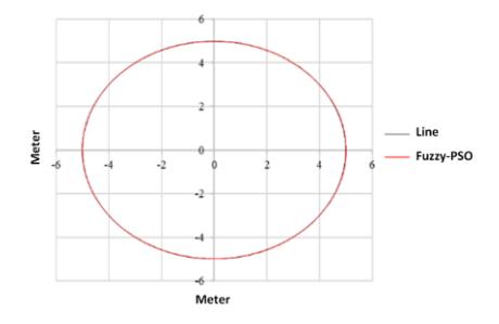
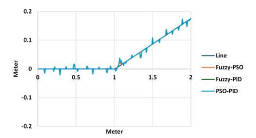
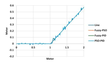
Electric vehicle running on a real circular track using the Fuzzy-PSO algorithm.
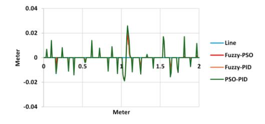
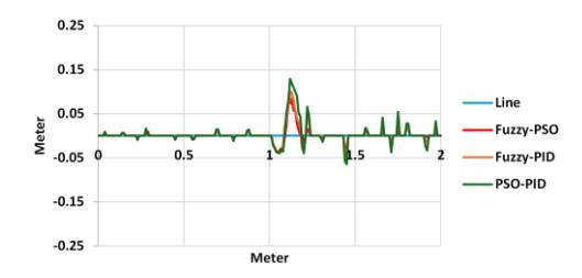
Figure 34 compares the experimental results of the standard circle with a radius of 5 m and the vehicle's center of gravity trajectory on the road surface, using the vector camera traction control algorithm based on the Fuzzy-PSO algorithm. The findings reveal that the autonomous vehicle handles road traction effectively, with relatively small errors. Figure 35 shows the error between the standard trajectory and the vehicle's center of gravity, with the largest deviation being 0.012 m and the smallest being 0.0025 m.
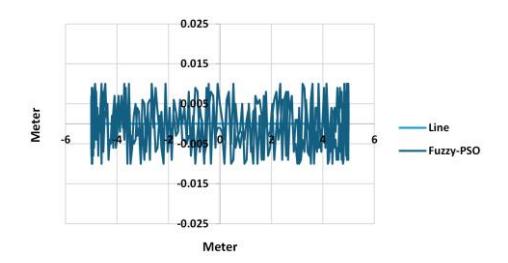
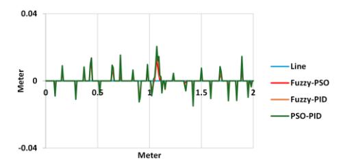
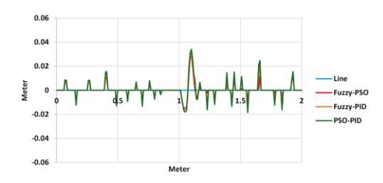
Error of real vehicle running on circular track using Fuzzy-PSO algorithm.
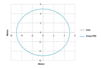
Electric vehicle running on a real circular track using the Fuzzy-PID algorithm.
Figure 36 compares the experimental results of the standard circle with a radius of 5 m and the trajectory of the vehicle's center of gravity following the road surface, using the vector camera traction control algorithm based on the Fuzzy-PID algorithm. The results demonstrate that the autonomous vehicle handles the traction well, yielding relatively small errors. Figure 37 shows the error between the standard trajectory and the vehicle's center of gravity, with the largest deviation being 0.016 m and the smallest being 0.0035 m.
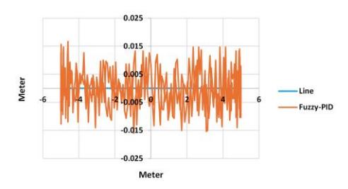
Error of a real vehicle running on circular track using the Fuzzy-PID algorithm.
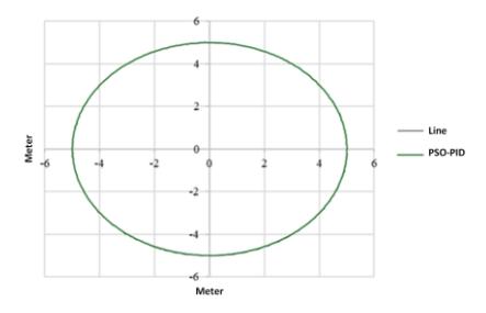
Electric vehicle running on a real circular track using the PSO-PID algorithm.
Figure 38 compares the experimental results of the standard circle with a radius of 5 m and the vehicle's center of gravity trajectory on the road surface, using the vector camera traction control algorithm based on the PSO-PID algorithm. The results demonstrate that the autonomous vehicle handles the traction well, yielding relatively small errors. Figure 39 shows the error between the standard trajectory and the vehicle's center of gravity, with the largest deviation being 0.018 m and the smallest being 0.0045 m.
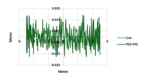
Error of the actual vehicle running on a circular track using the PSO-PID algorithm.
The effects of the actual vehicle running on a line and through corners are shown in the following table:
Table 6 Experimental results of actual vehicle running.
| Turning angle (degrees) | Average speed (m/s) | Successful results in 500 tests (%) | ||
|---|---|---|---|---|
| Fuzzy-PSO | Fuzzy-PID | PSO-PID | ||
| 0 | 1.86 | 100 | 100 | 100 |
|---|---|---|---|---|
| 10 | 1.72 | 99.8 | 99.5 | 99.3 |
| 20 | 1.58 | 99.5 | 99.2 | 99.1 |
| 30 | 1.46 | 99.4 | 99.1 | 98.8 |
| 40 | 1.32 | 99.2 | 98.5 | 98.2 |
Table 6 presents the results of 500 test runs of a vehicle running on the line for the corners of 0°, 10°, 20°, 30°, and 40°. Furthermore, it shows that when the vehicle runs on a straight line with a 0° turn, the average vehicle speed reaches 1.86 m/s and achieves a success rate of 100% compared to the remaining corners. Notably, the success rate and speed gradually decrease as the corner angles increase. In the experiment with a 10° turn, the algorithms maintained the vehicle's road grip at an average speed of 1.72 m/s. The success rates of the Fuzzy-PSO, Fuzzy-PID, and PSO-PID algorithms were 99.8%, 99.5%, and 99.3%, respectively.
Moreover, in the experiment at an angle of 20° with an average speed of 1.58 m/s, the electric car maintained effective control and good road grip. The success rates of the Fuzzy-PSO, Fuzzy-PID, and PSO-PID algorithms were 99.5%, 99.2%, and 99.1%, respectively. In the experiments at a 30° angle with an average speed of 1.46 m/s, the electric vehicle ran and maintained its good road grip. The success rates of the Fuzzy-PSO, Fuzzy-PID, and PSO-PID algorithms were 99.4%, 99.1%, and 98.8%, respectively. In the experiments at an angle of 40° with an average speed of 1.32 m/s, the algorithms maintained effective vehicle control and good road grip. The success rates of the Fuzzy-PSO, Fuzzy-PID, and PSO-PID algorithms were 99.2%, 98.5%, and 98.2%, respectively.
Based on the experimental results (Table 6 and Figures 35–39), the improvements of Fuzzy-PSO are explicitly calculated and discussed. For instance, at a 40° turn, Fuzzy-PSO achieved a success rate of 99.2%, compared with 98.5% for Fuzzy-PID, representing a 0.7 percentage point improvement (≈0.71% relative gain). Similarly, on the circular track, the maximum deviation of the vehicle trajectory was reduced from 0.016 m (Fuzzy-PID) to 0.012 m (Fuzzy-PSO), corresponding to a 25% error reduction. Compared to PSO-PID, the reduction was even larger, reaching 33.3%.
Table 7 Comparison with other studies.
| Controller | Maximum tracking error (m) |
|---|---|
| LQR (Hijikata et al., 2022) | 0.0044 |
| Fuzzy-PID (Pérez-Juárez et al., 2025) | 3.7 |
| Fuzzy-PSO | 0.012 |
Conclusion
In conclusion, this study highlights the successful construction and application of the Fuzzy-PID, PSO-PID, and Fuzzy-PSO algorithms for tracking self-driving electric cars running on roads using camera image processing technology. These algorithms utilize guidance lines at angles of 0°, 10°, 20°, 30°, and 40°, as well as circular paths with a radius of 5 m. The results of this study demonstrate the superior performance of the fuzzy-PSO control algorithm. Notably, the integration of Fuzzy Logic and PSO with the traditional PID controller improves system optimization, processing capacity, and flexibility. The implementation of the fuzzy control algorithm has enabled the self-driving car to respond quickly to the actual driving conditions of the electric vehicle, with feedback signals from the camera following the guidance lines. On the contrary, the Fuzzy-PID algorithm yields comparatively good results. However, the fuzzy algorithm fails to meet the system's control needs at certain value regions, requiring additional time to transition to a different value range for effective system control. Consequently, the vehicle's control response to steering directions may be delayed and slower. The PSO-PID algorithm gives good results, with the autonomous vehicle following the standard path. Nevertheless, its disadvantage is that it necessitates the integration of the steering speed of the fuzzy algorithm and the processing speed of the PSO algorithm to give the control signal for the vehicle to follow the guiding line detected by the camera. The time delay in finding the optimal PSO parameters is quickly addressed to reduce the deviation between the vehicle's central point and the standard guiding line.
The experiments evaluated the performance of the electric vehicle at angles of 0°, 10°, 20°, 30°, and 40°, considering its average speed and successful road tracking across 500 tests using the Fuzzy-PID, Fuzzy-PSO, and PSO-PID algorithms. As shown in Table 6, these control algorithms demonstrated optimal performance on a straight road, achieving an absolute success rate of 100% at an average speed of 1.86 m/s. On the circular track, the Fuzzy-PSO controller reduced the maximum trajectory deviation by 25% compared to Fuzzy-PID and by 33.3% compared to PSO-PID. Notably, the success rate of the electric vehicle's road grip decreases when encountering large corners due to the inertia of the electric car. When the electric vehicle is within the camera's recognition frame, it can still regain grip on the road. Nevertheless, the electric vehicle loses control of all controllers when the vehicle's inertia is extremely large and exceeds the camera's recognition frame.
In future research, the application of the Fuzzy-PSO method can be extended to larger-scale autonomous vehicles, with tests conducted under more complex environmental conditions (e.g., rain, limited visibility) and the integration of additional sensors such as LiDAR or GPS. Moreover, hybrid optimization strategies should be explored, such as combining Fuzzy-PSO with Genetic Algorithms or Grey Wolf Optimization.
Acknowledgement
This paper is supported with research funding by Project code: B2024-DHH-11 and Hue University under the Core Research Program, Grant No. NCTB.DHH.2024.08.
Compliance with ethics guidelines
The authors declare they have no conflict of interest or financial conflicts to disclose.
This article contains no studies with human or animal subjects performed by the authors.