
Introduction
A composite material comprises two or more constituent materials and possesses physical properties derived from these. Our work concerned fiber-reinforced composite comprising carbon fibers and the commercially available epoxy resin MTM710. Engineered composites of this type typically consist of two or more phases on a macroscopic scale, whose mechanical properties are designed to be superior to those of the constituent materials acting independently [1]. In general, composite materials are made up of reinforcement material (fibers, particles, or filler) embedded in a matrix (polymers, metal, or ceramic) that holds the reinforcement together. The reinforcement is the strongest part of the composite structure, and its main role is to enhance the mechanical properties of the new material.
The matrix should isolate the fibers from each other to work separately, protect the reinforcement from damage (e.g. abrasion) and environmental influences, and increase the composite's strength [2]. Fiber-reinforced polymer composites have been used successfully in many structural applications, and their use is expected to increase [3]. Composite materials have been used in many applications around the world where material mass is an important consideration [4-8]. Carbon fiber reinforced composites (CFRC) are widely used in different industrial applications due to their advantageous properties, including low density, high strength, heat resistance, and elastic modulus [6, 7].
Polymer composite reinforced fibers are widely used as high-performance materials in diverse industries such as automotive, rail, aerospace, sport, and civil engineering. These materials are attractive for all applications
Copyright ©2024 Published by IRCS - ITB J. Eng. Technol. Sci. Vol. 56, No. 1, 2023, 110-124 ISSN: 2337-5779 DOI: 10.5614/j.eng.technol.sci.2023.56.1.9
3Directorate of Al-Anbar Water Resources, Ministry of Water Resources, Anbar, Iraq that need high strength and low weight. Epoxy resins are most widely used for high-performance applications [8]. Lightweight materials such as aluminum, magnesium, and composites are being investigated for automotive applications [9-11]. Many authors have demonstrated that composite materials' structures designed to absorb impact energy possess high specific energy absorption (SEA) [8-14]. The combination of high SEA and mass reduction potential of composite materials has led to a significant research effort, particularly substituting metal components for composite alternatives. Plastics show a rate-dependent stress-strain response. Their behavior under dynamic conditions is different from that observed when loaded statically. It is influenced by the strain rate [15-18], which is essential to characterize when considering predictive numerical models since the stressstrain curve is a necessary input for predicting crashworthiness.
Several studies [19-24], have been conducted on different carbon/epoxy laminate types at different strain rates. These studies have shown an increase in both tensile strength and elastic modulus of composite coupons with increasing strain rates. In a recent study by Ramesh et al. [25], it was found that nano silica particles could be used to enhance the compression after impact strength of thin epoxy/GFRP composite laminates. The authors reported that laminates reinforced with 0.75 wt% nano silica exhibited a 91.5% increase in compressive strength compared to pristine laminates.
Finite element analyses are commonly used to model vehicle structures as a design activity to ensure compliance with various requirements, including legislation and consumer tests, and reduce the product development timescale. Explicit FE methods are used for crash simulation, with several crash solvers being commercially available, including ABAQUS, LS-Dyna, Pam-Crash, and RADIOSS [26]. ABAQUS has been used in the crash simulation of composite structures [27]. Recent updates have incorporated the capability to model composite layups by using conventional or continuum shell layup sections for both shell elements and solid layup sections for solid elements. The structure composite layup editor provides a table that allows users to define the number of plies in the layup [28]. Because of its broad application in the modeling of composites, especially of progressive damage and failure of nonlinear composite materials, ABAQUS was identified as a code capable of representing interest systems in this work [29]. ABAQUS/Explicit can solve dynamic equations and, although intended to solve highly dynamic problems, it can also solve quasi-static problems [14,30-32]. ABAQUS/Explicit and LS-Dyna are two software programs used to simulate low-velocity impact and analytical tools [32].
Metallic materials have been used widely to manufacture car bodies. The materials are subjected to many tests. These tests are used to simulate each component separately or the whole car under impact loading. The tests are used to optimize the characteristics of the vehicles [33].
Material and Experimental
Materials and Manufacturing (Composite)
The composite material used in this study was MTM710, an epoxy resin prepreg supplied by Cytec, with fibers having an orientation of ±45° and no twist, designed to offer mechanical properties that meet the performance requirements of automotive structural applications. The MTM710 matrix is a thermoset liquid resin that allows plaques to be manufactured using a rapid cure process in a hot compression mold. The plaque was under compression for three minutes and the curing temperature was typically between 130 and 150°C (266-302°F).
The composite plaques consisted of four plies with each ply comprising two layers giving a total thickness of between 2.6 and 2.8mm. Each ply was oriented at ±45° and cut using a Zund CNC Fabric Cutting Machine to get the finished 550 x 550 mm dimensions. To ensure a balanced lay-up, the upper face orientation was reversed on the lower face. Plaque density was determined using a weighing scale before and after the manufacturing process. The composite plaques were processed in a compression mold (press curing) with a vacuum applied during the process [34]. After the curing stage, the plaques were transferred to a cooling table where each plaque's edges were trimmed to remove surplus material.
The plaques were then labeled with a serial number and date of manufacture. Plaques were produced with the following ply orientation sequence: +45/-45/+45/-45/-45/+45/-45/+45 The plaques with physical characteristics
closest to the design specification were used for the tests. Those exhibiting defects such as matrix cracks or fibermatrix interface failure/delamination were rejected. The finished plaques' average weight was 1270 g, approximately 95% of the initial weight.
Experiment
Specimens of (25 mm*250 mm) of each composite orientation were tested with tensile loading. The specimens were designed to match the standard test method ASTM D3039/D3039M. An Instron 5800R 100kN test machine was used to test the specimens. A composite precision cutting machine was used to cut the plaques and prepare the specimens for testing. The composite specimens were mounted symmetrically about the mid-point of the gauge length such that 50 mm of material at each end was held in the jaws of the machine, giving a gauge length of 150 mm. Each specimen was marked with four dots to calculate the strain in the longitudinal and transverse directions, and specimen displacement was measured by a video extensometer (TELEDYNE DALSA). The tests were performed at room temperature and a speed of 2mm/min for the static tests.
For specimens with a fiber orientation of 0°/90° composite and metallic tabs were applied to both sides of each specimen to prevent gripping damage, metal, and composite tabs were cut to a length of 50 mm, and the width matched that of the specimens. An abrasive was used to roughen the surface of the tabs and then cleaned with Isopropanol. Glass balls with diameters of (0.2 to 0.3) mm were added to the epoxy system, with care taken to ensure a uniform distribution through mixing as well as a homogenous thickness between the tabs and specimens. The proportion of the epoxy and hardener was 1:1. The epoxy mixture was applied to both sides of the roughened area of the composite using a wooden spatula and the tabs were fixed in position using clamps. The specimens with tabs were cured in an oven at a temperature of 160-180 °C for four hours, after which the specimens were ready for testing. Care was taken to ensure the specimens were correctly aligned in the test machine grips to avoid any asymmetry that might affect the results.
Test Material
Quasi-Static Testing
Specimens were subjected to a tensile test to determine ultimate tensile strength and extension data, which was then used to validate the numerical models and compare the relative performance of the materials in the study. Tensile testing is an important engineering test in which a sample is subjected to a controlled tension (load) until failure. The ultimate tensile strength, elongation reduction in the transverse direction, and breaking strength are the properties that are directly measured in this test. Other properties are calculated based on these measurements, such as Young's modulus, Poisson's ratio, yield strength, and strain-hardening. These mechanical properties obtained from this test will be used in the numerical simulation.
For composite materials, several factors affect the specimen's tensile response and should be taken into consideration. These include volume fraction, fabrication method, fiber reinforcement architecture, specimen preparation and conditioning, specimen clamping system and alignment, test environment, test speed, load cell, and specimen clamping system [35].
Quasi-static tensile tests were performed on the composite specimens with both orientations of ±45° and 0/90° at ambient temperature using an Instron 5800R 100-kN test machine. A high-speed camera was used to measure the strain in the longitudinal and transverse directions, using four dots marked along the specimen's gauge length [36].
Figure 1 Composite specimens under quasi-static loading: (a) untested specimen, (b) 0/90° and ±45° ply orientation.
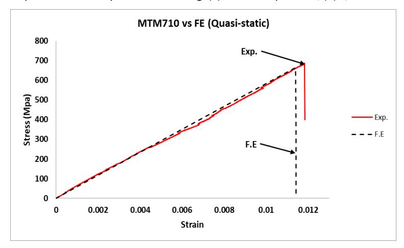
Figure 2 Quasi-static stress-strain curves for a composite material with 0°/90° ply orientation.
The stress-strain curve of the composite material (Figure 3) transits gradually and slowly. The curve is referred to as the plastic region. When the load was applied to the specimen in the tensile test, the specimen suffered a plastic region after a very short region of elasticity due to fibers pulling out easily because of the type of distribution (±45°) and the specimens reached the failure region quickly and deformed plastically and failed.
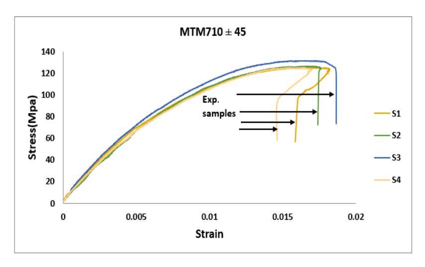
Figure 3 Quasi-static stress-strain curves for a composite material with ±45° ply orientation.
| Orientation (±45°) | Orientation (0/90) Tensile strength | |||
|---|---|---|---|---|
| Specimen No. | Tensile strength | |||
| Mpa | Mpa | |||
| 1 | 130 | 539 | ||
| 2 | 135 | 546 | ||
| 3 | 125 | 529 | ||
| 4 | 125 | 535 | ||
| 5 | 128 | 540 | ||
Table 1 Quasi-static ultimate tensile stress results of composite material.
Specimens for the metallic materials were manufactured from rectangular coupons using a Datron (M7 HP) CNC machine according to the geometry shown in Figure 4 from [42]. The ultimate stress properties are listed in Table 2 for all specimens. For the quasi-static test at a 2-mm/min speed, the dimensions were specified as in the standard test shown in Figure 4 below. The chemical composition of DP600 and AC170 are listed in Tables 3 and 4, respectively.
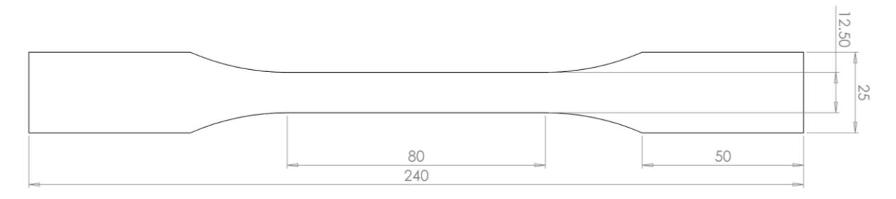
Figure 4 Metallic coupon specimen dimensions for quasi-static test.
Figure 5 Experimental metal specimens.
Table 2 Quasi-static ultimate tensile stress results from metals.
| DP600 | AC170 | 5754 Ultimate strength | ||
|---|---|---|---|---|
| Specimen | Ultimate strength | Ultimate strength | ||
| MPa | MPa | MPa | ||
| 1 | 573 | 212 | 195 | |
| 2 | 578.2 | 193.5 | 194.6 | |
| 3 | 584.15 | 205.6 | 192.7 | |
| 4 | 566 | 203.5 | 202.8 | |
| 5 | 582.6 | 205.4 | 195.4 | |
Table 3 Chemical composition of DP 600 steel / % [37].
| С | S | N | Mn | Р | Si | Al | Nb | V | Ti |
|---|---|---|---|---|---|---|---|---|---|
| 0.072 | 0.06 | 0.005 | 1.18 | 0.017 | 0.01 | 0.057 | 0.002 | 0.003 | 0.001 |
Table 4 AC170 chemical composition [38].
| Si% | Fe% | Cu% | Mn% | Mg% |
|---|---|---|---|---|
| 0.6 | 0.16 | 0.14 | 0.06 | 0.7 |
High Strain Rate
The specimens were tested at 1 and 5 m/s. The dimensions of the dynamic tensile specimen were (\(200 \times 29 \times 2.6\)) mm. The stacking sequence was [45/-45/45/-45/-45/45/-45/45] The specimens were cut with a ply orientation of [\(0/90^{\circ}\) and \(\pm 45\)]. 50-mm long metal tabs were glued to both sides of the specimens as in the quasistatic test. All tests were performed at room temperature using an Instron VHS 160/100-20 very high strain-rate testing machine (Figure 7) capable of achieving a velocity range of 1 mm/s to 20 m/s, strain rates from quasistatic to 1000 /s with a load capacity of up to 100 kN. A wire with a diameter of 0.1 mm was used instead of glass balls to ensure a uniform thickness over each tab and specimen's glued area. This was achieved by wrapping the wire around the specimens at both ends for a distance corresponding to the tab's length. Epoxy resin and hardener were applied to the tabs with a spatula and the tabs were held in place using clamps.
(a) Composite material with orientation (0/90)
(b) Composite material with orientation (±45)
Figure 6 Composite samples under high strain rate loading: a fiber breakage b) shear and fiber pull-out.
Each composite specimen's gauge length was painted to create a stochastic pattern for Digital Image Correlation (DIC) (FASTCAM SA-X2 5000 frame/sec) sensors to measure the strain in both the longitudinal and transverse directions. Figure 6 shows the type of failure under a high strain rate for different orientations. The mechanical properties determined from experimental data for composite specimens are listed in Table 5 below.
Table 5 Mechanical properties of MTM710 at a high strain rate.
| Orien | tation (±45) | Orientation (0/90) | |||
|---|---|---|---|---|---|
| Specimen | Tensile strength MPa | Young Modulus (GPa) | Tensile strength MPa | Young Modulus (GPa) | |
| 1 | 187 | 13 | 695 | 66 | |
| 2 | 185 | 12 | 700 | 67 | |
| 3 | 182 | 13.5 | 697 | 66 | |
The same experimental conditions used for the composite specimens were applied to the metallic reference materials DP600 and AC170. The specimen geometry for dynamic testing is shown in Figure 7 [39]. The ultimate strength and modulus of elasticity of metallic specimens for both materials are shown in Table 6 below. Figure 8 represents the fast jaw technique used in the high-strain rate tests.
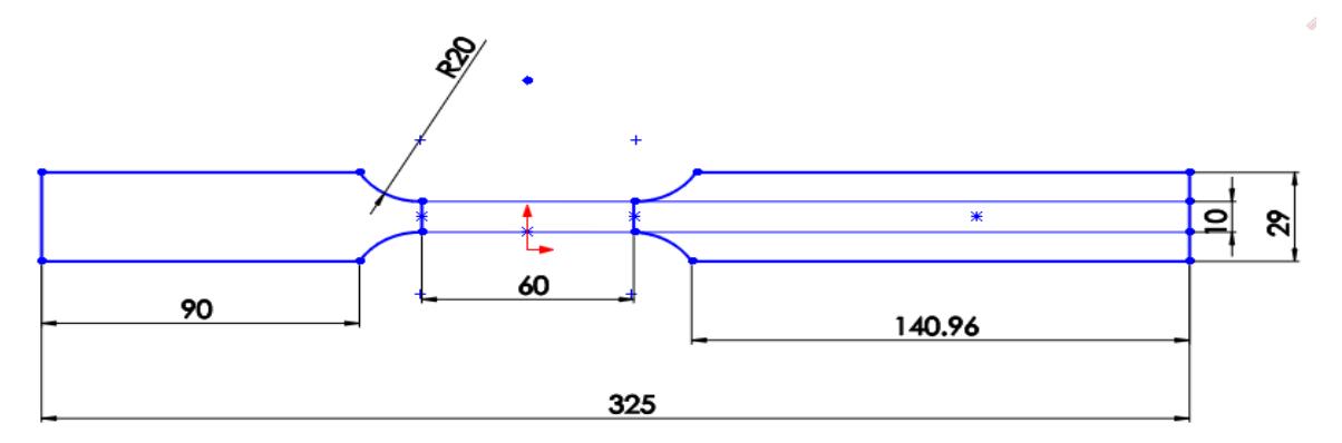
Figure 7 Specimen geometry for high strain rate testing.
Table 6 Ultimate strength for DP600 and AC170 at high strain rate.
| Test speed Specimen (m/s) | Ultimate strength (MPa) DP600 | Ultimate strength (MPa) AC170 | ||
|---|---|---|---|---|
| 1 | 1 | 683.5 | 251.6 | |
| 2 | 1 | 673 | 225 | |
| 3 | 1 | 670 | 252.4 | |
| 4 | 5 | 734.5 | 335.4 | |
| 5 | 5 | 727.2 | 343.6 | |
| 6 | 5 | 780.7 | 332.2 | |
Figure 8 Fast-jaw system (Instron VHS 160/100-20) to test at high strain rates.
Simulation
The non-linear finite element (FE) code ABAQUS/Explicit was used to predict the response of the carbon fiberreinforced composite, aluminum, and high-strength steel specimens for both quasi-static and high strain rate testing.
This study's model was constructed using four-node linear conventional shell (S4R) elements combined with reduced integration, hourglass control, and a standard linear geometric order. Hourglass control was used to avoid artificial, zero energy, deformation, and reduced integration. The advantage of using shell elements in modeling is that it results in relatively short runtimes and low disk space consumption. The element size used was 2 mm with specimens meshed using quadrilateral geometry. The specimen was modeled as a coupon with the tensile load subjected to one end of the specimen only. The other end was constrained using the Symmetry/Antisymmetry/Encanstre category (U1= U2 = U3 = UR1 = UR2 = UR3 = 0), representing the fixed jaw of the tensile equipment. The tensile load was applied as linear displacement of the mobile jaw along with the specimen (U1) while other displacements were fixed (U2 = U3 = UR1 = UR2 = UR3 = 0). The motion was modeled as a static general step. The thickness of the specimen was 2.6 mm
The specimen's material was modeled as lamina consisting of four layers with a single-layer thickness of 0.65 mm. Each layer consisted of bidirectional fibers with an orientation of [+45°/-45°]2S.
The predicted results are summarized in Table 7, representing both the tensile stress and the modulus of elasticity at quasi-static loading. For the dynamic modeling (high strain rate), one side of the specimen was constrained in all degrees of freedom. Simultaneously, the motion was modeled on the other side as an explicit step with a linear velocity of 1,000 and 5,000 mm/s along the direction of the specimen while other linear and rotational velocities directions at the same end were modeled as zero.
Results and Discussion
This paper presents the FEA simulation of carbon-reinforced MTM710, an epoxy resin prepreg matrix. Finite element results are presented for the three different test speeds (quasi-static, dynamic 1 mps, and 5 mps) for the composite and different metals. Figures [9-15] represent the experimental curves for the quasi-static and high-strain tests. The composite's mechanical properties were predicted using ABAQUS and compared with the experimental values to validate the quasi-static and high strain rate (Figures 16, 23).
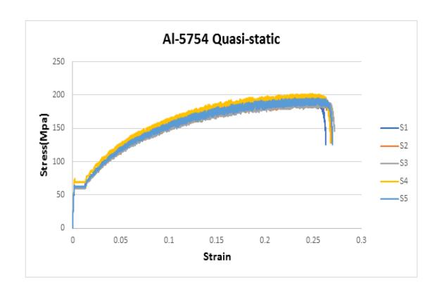
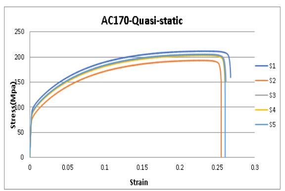
Figure 9 Quasi-static tensile test for 5754. Figure 10 Quasi-static tensile test for AC170.
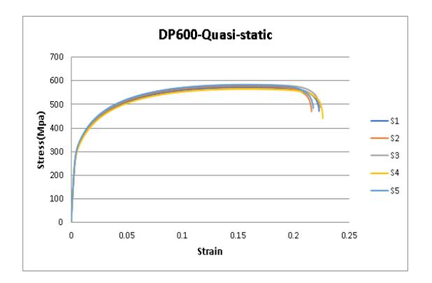
Figure 11 Quasi-static tensile test for DP600. Figure 12 High strain (1 mps) for AC170.
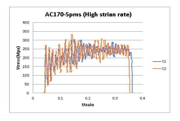
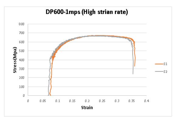
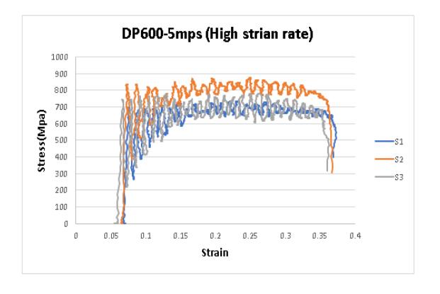
Figure 13 High strain (5 mps) for AC170. Figure 14 High strain (1 mps) for DP600.
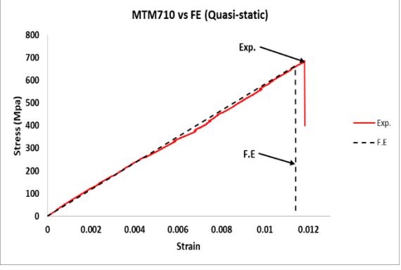
Figure 15 High strain (5 mps) for AC170. Figure 16 Composite material vs FE (quasi-static).
From the analysis of the composite, it could be seen that the stress and strain curves of the predicted results were very close to the values obtained from the experimental tests. It is not easy to make the specimen's geometry precisely the same as that of the simulated one, so there was a difference in values among specimens. These differences are attributed to the specimen's misalignment during cutting, variations in thickness and width and the specimen and distribution in the volume fraction of each sample. The difference between the predicted and experimental results is considered normal experimental variation and seems acceptable. The experimental results and the predicted results are listed in Table 7 below.
| Specimen no. | Tensile strength (MPa) Exp | Tensile strength (MPa) FE | Error % | Young Modulus (GPa) Exp | Young Modulus (GPa) FE | Error % |
|---|---|---|---|---|---|---|
| 1 | 539 | 2.8 | 53.2 | 6.2 | ||
| 2 | 546 | 4 | 47.8 | 0 | ||
| 3 | 529 | 524 | 1 | 47.9 | 49.2 | 0.4 |
| 4 | 535 | 2 | 52.8 | 6 | ||
| 5 | 540 | 3 | 48.8 | 2 |
Table 7 Experimental results of composite material v. FE at quasi-static stress conditions.
The mechanical properties of the metal specimens are listed in Table 8. From the results, it can be noted that the ultimate stress increased with the strain rate.
| - 0- | |||||
|---|---|---|---|---|---|
| Material | Ultimate strength (Mpa) | ||||
| Speed | Static | 1 (m/s) | 5 (m/s) | ||
| DP600 | 573 | 683.5 | 734.5 | ||
| DP600 | 578.2 | 673 | 727.2 | ||
| DP600 | 584.15 | 670 | 780.7 | ||
| AC170 | 205.6 | 251.6 | 335.4 | ||
| AC170 | 203.5 | 225 | 343.6 | ||
| ΔC170 | 205.4 | 252 / | 332.2 | ||
Table 8 Ultimate strength for DP600 and AC170 at different speeds.
The predicted results were validated by experimental tests (Figures 17-24). The finite element results for the composite material showed a significant level of correlation with the experimental results. The simulation results seem well suited for predicting the mechanical properties through the stress-strain curves of the composite structure and the metals. The predicted results of the composite were closely similar to those obtained by the experimental tests the average percentage differences were below 5%, which is quite small. The mechanical properties of both AC170 and DP 600 steel seemed sensitive to the strain rate. The values of the metals showed a noticeable increase in both tensile strength and modulus of elasticity. The modeling approach could predict the behavior of the materials used under different tensile loading conditions, as the test results confirmed. The findings of this study demonstrate similar trends to Lazar et al. [40], particularly in how cell topology, relative density, and loading direction impact the compressive properties of fiber-reinforced structures.
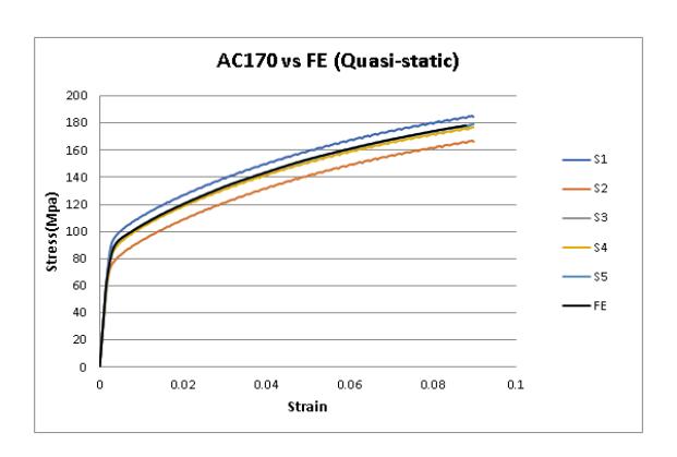
Figure 17 AC170 vs FE (quasi-static).
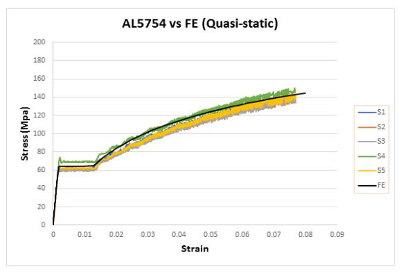
Figure 18 AL 5754 vs FE (quasi-static).
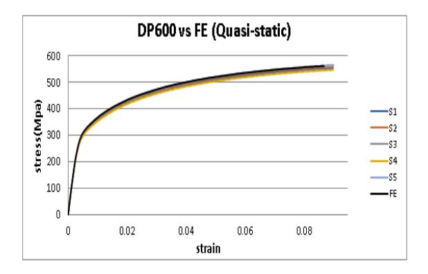
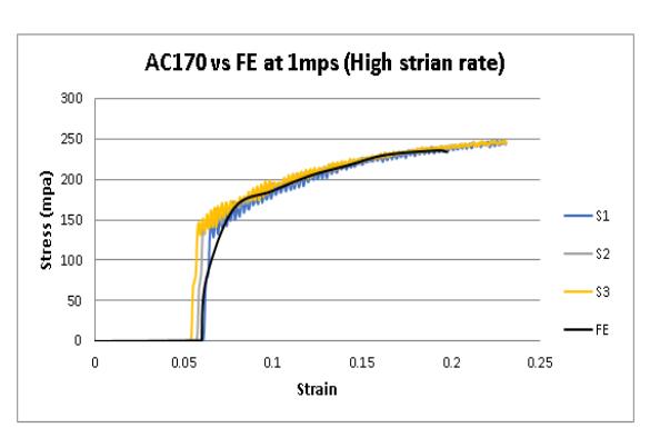
Figure 19 DP600 vs FE (quasi-static). Figure 20 AC170 vs FE (high strain rate).
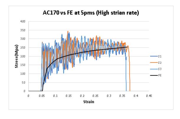
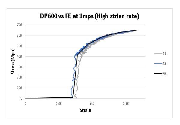
Figure 21 AC170 vs FE (high strain rate). Figure 22 DP600 vs FE (high strain rate).
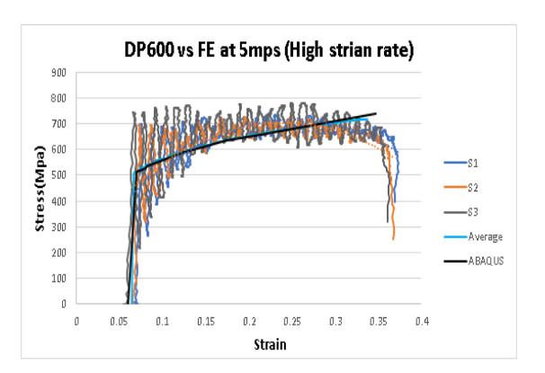
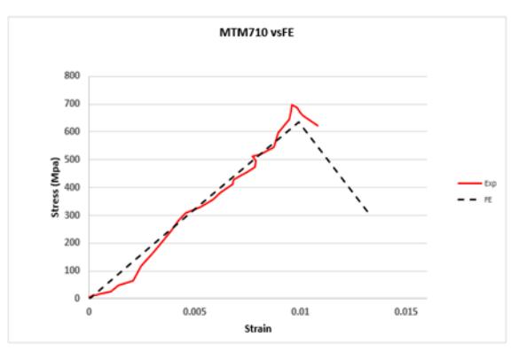
Figure 23 DP600 vs FE (high strain rate). Figure 24 Composite material vs FE (high strain rate).
Figure 25 shows the behavior of the composite samples when subjected to quasi-static and high-strain loading. The figure confirms that the composite material did not have a significant effect on the strain rate level used (10 and 50 −1
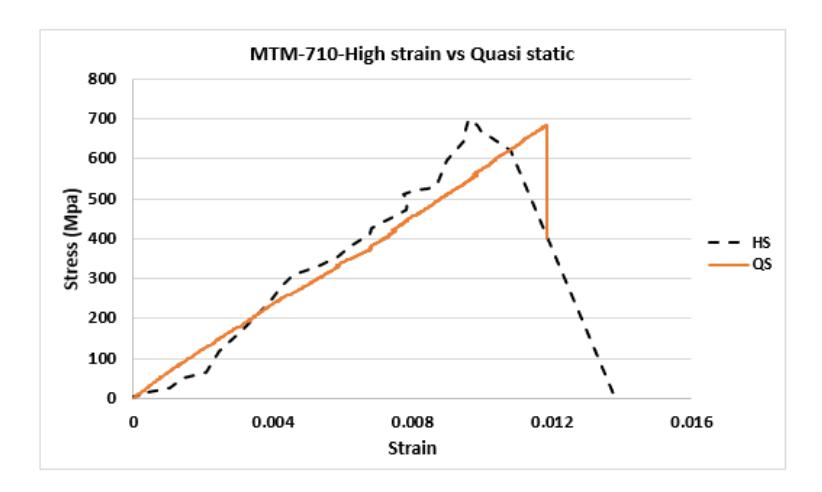
Figure 25 Composite material high strain rate vs quasi-static.
Samer Abdulqadir and Faris Tarlochan [5] presented a Top-Hat Tubular Structure Subjected to Axial Crush. The structures were made of carbon composite prepregs MTM-44 under different impact speeds. The experimental results were used to validate the numerical results of the study.
The study confirmed that the predicted results produced by numerical methods demonstrated a strong agreement with the experimental data (Figure 26), indicating the ability to predict the specimens' failure. The work also demonstrated how unique it is to use these kinds of structures in energy absorption applications.
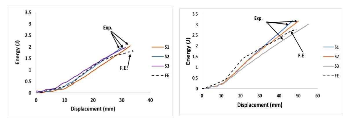
Figure 26 Energy-displacement curve for the top-hat section under crush loading at different speeds.
Another study[6] conducted an experimental study and numerical modeling of a thin-walled top-hat section made of carbon composite prepregs under dynamic and static flexural loading at varying impact speeds. The study validated the experimental results with finite element predictions which confirmed that the predicted results were in good agreement with the experimental results (Figure 27).
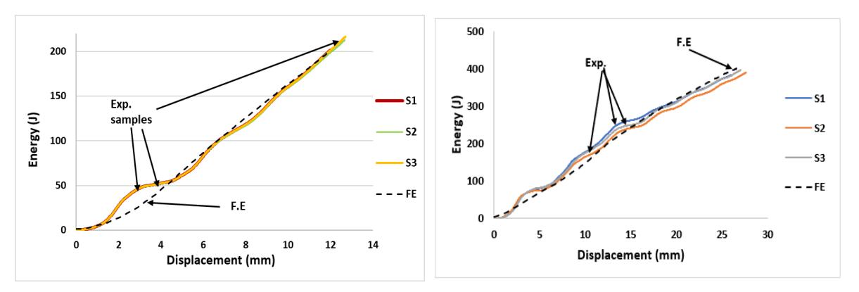
Figure 27 Energy-displacement curve for the top-hat section under flexural loading with different speeds.
Conclusions
A preliminary finite element analysis to model the behavior of a fiber-reinforced carbon/epoxy prepreg composite was presented in this paper. The finite element method was used to predict the material's behavior under quasi-static and high strain rates. The physical and numerical results comparison demonstrated that the modeling approach used for this work could accurately predict the mechanical behavior of a fiber-reinforced composite manufactured using carbon fiber and the commercially available epoxy resin MTM710. The comparison of composite, aluminum, and high-strength steel indicated that the composite can be used as an alternative to aluminum and high-strength steel since it appeared to have almost the same strength as steel and higher strength than aluminum with the advantage of being lightweight and possessing similar mechanical behavior under quasi-static conditions. For a dynamic high strain rate, the tests showed that the metals were influenced by the strain rate and behaved as dependent on the strain. Figures (15-23) show the modeling approach that could predict the mechanical properties; behavior of different materials under quasi-static and high strain rates. The study exhibited interesting considerations regarding selecting materials that FEA can optimize based on mechanical properties, cost, and weight. This will significantly reduce the new product introduction timescale, which is important for the wider use of polymer composites for structural applications, especially within the transportation industry.
Acknowledgments
The Council for the At-Risk Academy financially supported this study (CARA). The authors would like to acknowledge the University of Warwick and Warwick Manufacturing Group (WMG) and the staff for providing full support, equipment, advice, and facilities to complete this research.