
Introduction
With the rapid development of the rail transit industry, the demand for high operating speeds places higher demands on the performance of rail vehicles. The car body, making up a large part of the rail vehicle, accounts for a large proportion of the weight of rail transit equipment. Conducting lightweight research on rail vehicle bodies can greatly reduce the weight of rail transit equipment. By choosing materials that are lightweight but have high strength, such as aluminum alloy, carbon fiber composite materials, and so on, traditional steel structures can be replaced. This reduces the weight of the vehicle while increasing its strength and rigidity.
Yan et al. [1] proposed that China's rail transit industry is relatively backward in the design and application of chemical composite materials and suggested that polymer materials such as carbon fiber can be used for lightweight rail vehicles. Liu et al. [2] verified the feasibility of carbon fiber composite materials in rail vehicles from the aspects of structural material design, vehicle structure design, and car body forming technology. Zhou, Wang et al. [3-4] considered the structural design of a train body from the perspective of carbon fiber composite materials and used the finite element method on the strength, stiffness, and mode of the vehicle structure for verification and analysis. Under the premise of meeting the relevant design requirements, a carbon fiber body is 42% lighter than a traditional aluminum alloy body. Hou et al. [5] expanded upon the technical difficulties of lightweight composite materials in rail transit from the dimensions of system engineering, including structural light weight, safety, comprehensive comfort, and sustainable development. Li et al. [6] conducted lightweight research on rail vehicle bodies, bogies, interior materials, etc. The results showed that lightweight rail trains can
Copyright ©2024 Published by IRCS - ITB J. Eng. Technol. Sci. Vol. 56, No. 3, 2024, 353-366 ISSN: 2337-5779 DOI: 10.5614/j.eng.technol.sci.2024.56.3.4
2Nanjing Metro, No.228 Zhongshan Road, Xuanwu, Nanjing and 210018, China
promote energy-saving, low-carbon, green, and sustainable development of cities while bringing direct economic benefits.
Kang et al. [7] studied the processing parameters of CFRP plate and 5083 aluminum plate and compared the high cyclic fatigue properties of the two. The results showed that CFRP material can replace aluminum sheets to achieve the purpose of weight reduction. Tang et al. [8] studied the feasibility of pultruded glass fiber reinforced polymer GFRP as a lightweight alternative material for railway vehicle bodies. The finite element analysis showed that the design of the composite structure not only meets the mechanical requirements but also reduces the weight of the design by 35.5% compared with the original design using steel plate. Thomas et al. [9] found that magnesium and its alloys have superior mechanical properties at a light weight and proposed that magnesium alloys have great application potential in railway vehicles. Lei et al. [10] analyzed the mechanical properties, processing and casting, manufacturing cost, safety, and other aspects of magnesium alloy and verified that the structural properties of a magnesium alloy car body meet the relevant requirements. The results showed that the weight of a magnesium alloy body can be reduced by 10% compared with an aluminum alloy body.
At present, most of the designed rail vehicle bodies are made of aluminum alloy hollow profiles. However, the arrangement of the internal structure of a hollow profile does not fully consider the running performance of the rail vehicle while its structure often has a large margin. Therefore, many scholars have carried out research on the structural design of the car body. Zheng, Li et al. [11-12] took an aluminum alloy car body structure as the research object and introduced the static stiffness sensitivity analysis method for the structure. While reducing the mass of the car body, the overall stiffness of the structure and the frequency of first-order sag bending are basically not affected. Gao, Yao et al. [13-14] determined the effective design variables through sensitivity analysis and based on the multi-objective optimization theory. Within the safety limits of stiffness and modal characteristics, the goal of reducing the weight of the vehicle body and reducing the noise in the vehicle interior was achieved.
Lee et al. [15] verified the feasibility of magnesium alloy as body material based on the gradient optimization algorithm and a numerical simulation. Magnesium alloy as a body material can reduce the total weight of a locomotive by 2%. Miao et al. [16] proposed a multidisciplinary design optimization method for fatigue life prediction of lightweight car bodies based on finite element theory. Koenig et al. [17] obtained an economical and weight-reducing design scheme for a frame structure through topology optimization, which significantly improved the performance while realizing a lightweight vehicle body. Jiang, Kang et al. [18] put forward corresponding measures for the lightweight design of rail transit vehicles from the aspects of material selection, component design, connection technology, and system function integration.
To sum up, to improve the structural performance of the car body and at the same time obtain a reasonable body structure for rail vehicles, it has become a research hotspot to realize a lightweight design under the condition of ensuring the performance of the car body. By using advanced optimization techniques such as finite element analysis and topology optimization in the design of the car body, the car body structure can be optimized, redundant material can be reduced, and the strength and stiffness of the structure can be improved to achieve a light weight. However, the structure of the rail vehicle body obtained under a single working condition makes it difficult to meet the multiple loads borne by the train in service at the same time, while the vibration resistance of the train body in the service process also needs to be used as an index point.
In this paper, the variable density topology optimization method and the size optimization method based on sensitivity analysis were used to design the rib plate structure of the car body section, to maximize the utilization rate of the materials so as to reduce the weight of the car body structure while meeting the relevant standards of the car body structure, and to improve the structural performance of the rail vehicle body and the overall carrying capacity of the train. Through strength and modal analysis of the rail vehicle body, the bearing and vibration data under actual operating conditions were obtained. The optimized lightweight car body can avoid stress overrun and at the same time ensures that the first-order vertical bending frequency is far away from the bogie nodding frequency, which avoids the problems of resonance in the operation of the rail vehicle, affecting the service life of the train. A light weight of subway vehicles cannot only improve their running speed but also reduce the traction energy consumption and noise pollution caused by trains in operation. It improves the ride stability of the train and prolongs the service life of the vehicle and the line. A light weight of the car body has important practical significance for the development of rail vehicles.
Topology Optimization of the Rail Vehicle Body Cross-Section
Method for Topology Optimization of the Rail Vehicle Body Cross-Section Structure
The essence of topology optimization of the rail vehicle body cross-section structure is to obtain the optimal force transmission path of the car body structure under load by determining the presence or absence of cross-section materials. Its mathematical model can be expressed as in Eq. (1):
Find \[\rho = (\rho_1, \rho_2, \cdots, \rho_N)^T\]
\[\min C(\rho) = F^T U\]
s.t. \[\begin{cases} A \leq f A_0 \\ F = K U \\ \rho_i \in [0,1] (i = 1,2,\cdots, N) \end{cases}\]
(1)
where \(\rho_i\) is the design variable, T denotes the relative density of the cells; N is the total number of units; K is the total stiffness matrix of the car body section; U is the displacement vector of the cross-sectional structure; F is the vector of the external force on the cross-section; A is the area of the optimized rear body section; \(A_0\) is the original area of the body section; f is the area constraint parameter; f is the upper limit of the optimized volume.
In this paper, the cross-section of the roof and side wall of the rail vehicle was selected as the optimization object. The optimization results of the rail vehicle body under operating conditions could be obtained based on the above model. However, the roof and side walls of rail vehicles have different performance requirements due to wind load during vehicle operation, so this paper obtained a reasonable layout of the cross-sectional structure of the rail vehicle body at the same wind speed and different wind directions. The topology optimization was carried out with the moment of inertia and the cross-sectional area of the rail vehicle body section as constraints, while the stiffness of the rail vehicle body section was taken as the goal. In order to solve the singular optimization results caused by different working loads, the compromise programming method was used to modify the objective function of the topology optimization described in Eq. (2):
\[\min_{\rho = (\rho_1, \rho_2, \dots, \rho_N)^T} C(\rho) = \left\{ \sum_{k=1}^m \omega_k^q \left[ \frac{C_k(\rho) - C_k^{\min}}{C_k^{\max} - C_k^{\min}} \right]^q \right\}^{\frac{1}{q}}\] (2)
where m is the number of load cases set; \(w_k\) is the weight of the k-th case, the sum of the weights of all working conditions must be 1, in this study, the same weight was taken for all working conditions; q is a penalty factor, \(q \ge 2\); \(C_k(x)\) is the compliance objective function of the k-th case; \(C_k^{min}\) is the minimum value of the objective function of the k-th working case; and \(C_k^{max}\) is the maximum value of the objective function of the k-th case.
Topology Optimization of Rail Vehicle Body Cross-Section Structure under Single Wind Load Condition
Under the condition of lateral wind pressure, that is, when the external force on the side of the rail vehicle body is only the cross wind during train operation, the static stiffness of the roof and wall section of the rail vehicle body was optimized to obtain the best force transmission structure of the rail vehicle body section structure under this working condition. Figure 1 shows the internal rib structure of the selected rail vehicle body cross-section optimization object. The rib structure is mainly concentrated in the upper and lower side beam areas of the side wall. In order to compare with the results after the subsequent optimization, the moment of inertia in the plane of the cross-section was first analyzed. The results before optimization are shown in Table 1. Under the condition of single lateral wind pressure, the side of the rail vehicle body is only affected by the cross wind during operation. The wind load \(q_w\) is evenly applied to the side of the rail vehicle body, the angle with the vertical direction of the rail vehicle body is \(\alpha\), and the air conditioning load \(q_a\) is distributed on the roof.
Cross-section structure diagram of the vehicle body.
Table1 Inertia moment data in the plane of the vehicle body section before optimization.
| Direction of action of moment of inertia | Moment of inertia/mm4 |
|---|---|
| X coordinate axis | 2.013 × 10¹¹ |
| Y coordinate axis | 8.471 × 10¹⁰ |
| X direction shaft | 3.451 × 10¹⁰ |
| Y direction shaft | 8.471 × 10¹⁰ |
The established finite element model for structural topology optimization is shown in Figure 2. The inner and outer masking plates of the rail vehicle body section were set as non-design areas and the rib plate area was simplified into a closed surface structure and set as the design area, as shown in Figure 3.
FEA model of vehicle body section. FEA model of vehicle body section.
In order to prove the necessity of multi-condition optimization of the rail vehicle body structure, in this paper, firstly, under wind load angles of α 15° and 60°, the determined vehicle body interface was optimized for a single target. The optimization results of the cross-section of the rail vehicle body obtained after using the OptiStruct
module in the HyperWorks software are shown in Figure 4. The density threshold range of the elements in the optimization results was 0 to 1; the different colors in the optimization result contour represent different relative densities, and the transition from blue to red represents the transition from 0 to 1 relative density. An area with a high relative density indicates that it is subjected to a large load and should be retained. An area with a low relative density indicates that the load is low and belongs to the material removal area, from which the optimal force transmission path of the cross-section structure can be obtained.
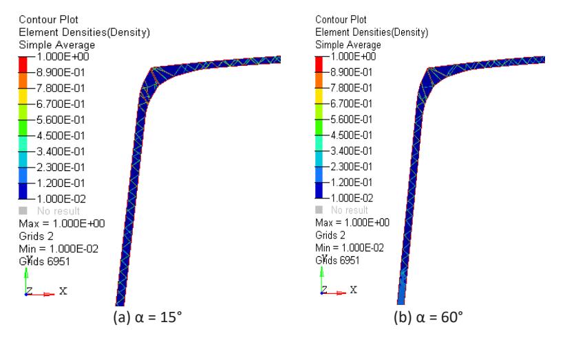
Topology optimization results of cross-sectional structure of rail vehicle body under single working conditions.
By comparing the optimization results under the conditions of 15° and 60° wind load action angles, it can be seen that when the material removal rate is the same, the rib structure of the side wall gradually decreases. At 60°, the force on the side wall part is not large and the inner and outer plate structures of the side wall in this area mainly play a positioning role, while the lower part bears relatively large loads so that a dense rib plate structure appears. Because the topology optimization results are greatly affected by loads and constraints under different working conditions, the optimal force transmission path is affected accordingly and its stiffness performance is also different. Therefore, topology optimization of the cross-section structure of the rail vehicle body under a single working condition cannot meet the requirements of multiple working conditions for the performance of the rail vehicle body at the same time. This means that the acquisition of the optimal force transmission path of the cross-section of the rail vehicle body needs to consider the factors of multiple working conditions.
Optimization of Multi-Working Conditions of Cross-Section of Rail Vehicle Body Under Wind Load
Topology Optimization of Multi-Condition Structure of Rail Vehicle Body Cross-Section
By optimizing the stiffness of the roof and side wall sections under a single working condition, the flexibility values of the roof and side wall before and after optimization were obtained. In order to maximize the bearing capacity of the structure, the minimum flexibility (maximum total potential energy or minimum strain energy) of the structure under various loads was taken as the objective function under the corresponding load and the overall volume and moment of inertia of the rail vehicle body section structure were taken as the constraints under stiffness optimization. Based on the weighted compromise programming method, the multi-objective function optimization problem under multiple working conditions was transformed into a single-objective function optimization problem. In this paper, wind load angles of 15°, 30°, 45°, and 60° were selected as working conditions in the subsequent optimization process. Combined with Eq. (2), a mathematical model of topology optimization of the cross-section structure of the rail vehicle body under multiple working conditions was established and the layout results of the cross-section rib plate structure of the rail vehicle body under the action of multiple working conditions were obtained as shown in Figure 5.
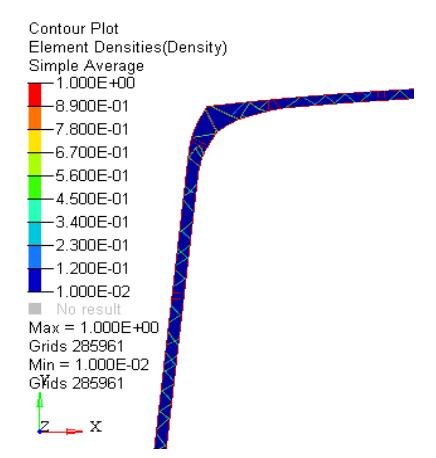
Topology optimization results of multi-working condition of vehicle body cross-sectional structure.
By comparing with the single-case optimization results in Figure 4, the multi-condition topology optimization results of the cross-section structure of the rail vehicle body become clearer and more explicit. The singlecondition optimization only considers the performance of the rail vehicle body section under a specific working condition, while the multi-condition optimization establishes a more accurate model. Considering the influence of different loads on the performance of the rail vehicle body from the perspective of multiple wind loads, it can consider the performance requirements of the system under various typical working conditions, so that the calculation results are more realistic, thereby improving the accuracy and reliability of the optimization.
Cross-Section Reconstruction Based on Optimization Results
Based on the topology optimization results of the rail vehicle body cross-section structure under multiple working conditions shown in Figure 5, the reconstruction results of the rail vehicle body cross-section structure were obtained as shown in Figure 6. The mass of the railway vehicle body section stiffened plate was 0.585 t. The weight loss rate was 4.47% compared to before optimization. The moment of inertia in the cross-section of the rail vehicle body after optimization is shown in Table 2.
Table 2 In-plane moment of inertia data for body sections after optimization.
| Direction of action of moment of inertia | Moment of inertia/mm4 | |
|---|---|---|
| X coordinate axis | 1.814 × 10¹¹ | |
| Y coordinate axis | 7.411 × 10¹⁰ | |
| X direction shaft | 2.891 × 10¹⁰ | |
| Y direction shaft | 7.411 × 10¹⁰ | |
Results of reconstruction of the cross-sectional structure of rail vehicle body.
Compared with the stiffness optimization results under a single working condition, the stiffness optimization results obtained under multiple working conditions comprehensively considered the bearing characteristics of the cross-section structure of the rail vehicle body under different load conditions and the rib plate layout distribution of the cross-section was more uniform. Compared with before optimization, the moment of inertia of the body section decreased slightly. After the optimization, the structure of the straight rib plate at the connection position between the original side wall and the roof was changed to an approximately continuous triangular diagonal rib plate structure, which improves the stability of the structure. The layout of the ribs is relatively uniform and the utilization rate of materials was also improved.
Performance Analysis of Rail Vehicle Body with Reconstructed Cross-Section Features
According to the requirements of the design load conditions in the relevant design standards of EN12663:2010 – Railway applications – Structural requirements for railway vehicle bodies [19], performance analysis of the rail vehicle body structure after multi-condition optimization was carried out under overcrowding compression conditions, overcrowding conditions, and maximum operating load conditions. The vertical displacement results of the rail vehicle body under different working conditions were obtained as shown in Figure 7. As shown in Figure 7(a), the maximum vertical displacement of the body unit was 6.58 mm under the condition of overcrowding compression. Under this condition, the rail vehicle body is affected by its own gravity and longitudinal compressive load, and the local stress values of the slow weld of the pillow, the door angle of the passenger compartment, the window angle, and the end beam of the rail vehicle body were larger and the overall force is obvious. When the force flow at the coupler is transferred to the weld between the sleeper beam and the side beam, the abrupt change in the cross-sectional area leads to a local high stress. Due to the change of the cross-section rib plate structure, the roof also bore greater stress and the phenomenon of stress concentration of the rail vehicle body structure has been improved to a certain extent.
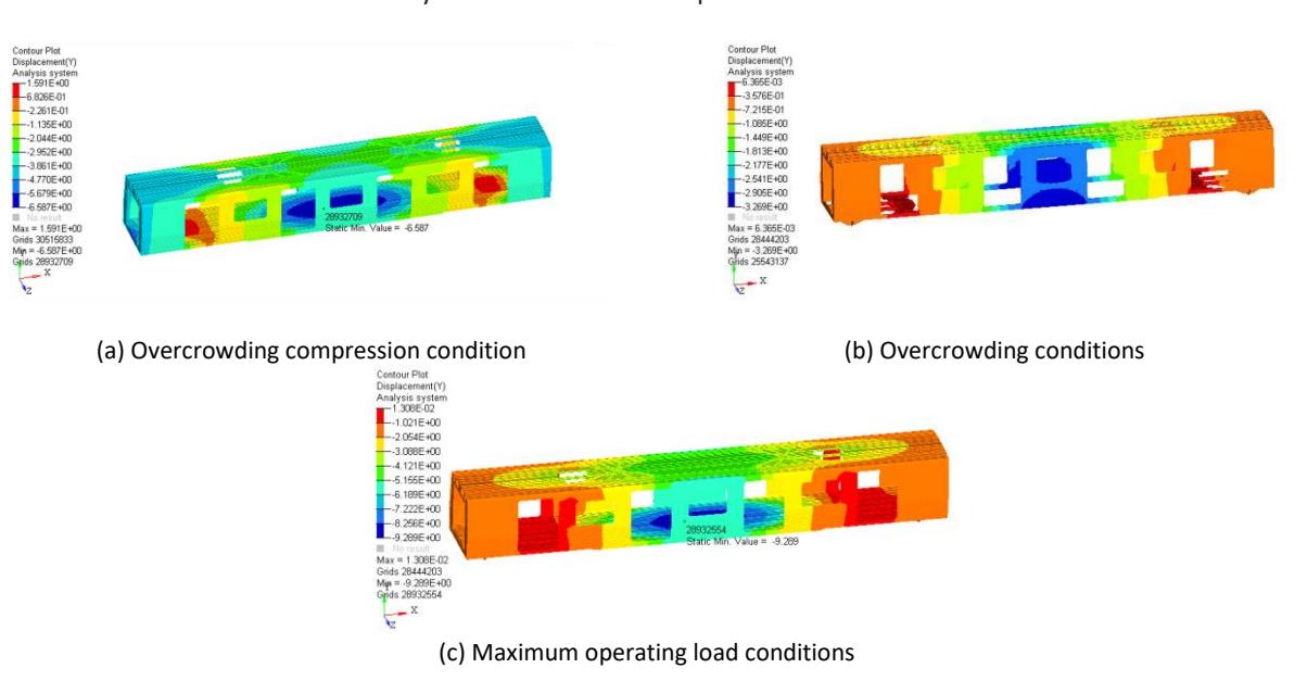
Results of vertical displacement of the rail vehicle body under different working conditions.
The vertical displacement of the rail vehicle body structure under the condition of over-working is shown in Figure 7(b). The vertical displacement of the center of the underframe side beam was 3.26 mm under the condition of overcrowding. The considerable bending stiffness of the rail vehicle body under this condition was 1.41 × 10⁹ N/m2 , which meets the stiffness requirements of the rail vehicle body. The vertical displacement of the rail vehicle body under the maximum operating load condition is shown in Figure 7(c) and the vertical displacement of the rail vehicle body was 9.28 mm when the rib plate between the side wall and the roof of the rail vehicle body was rearranged, which was reduced compared with the pre-optimization displacement, indicating that the stiffness of the rail vehicle body was improved under this condition.
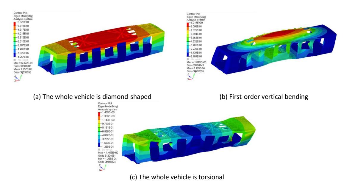
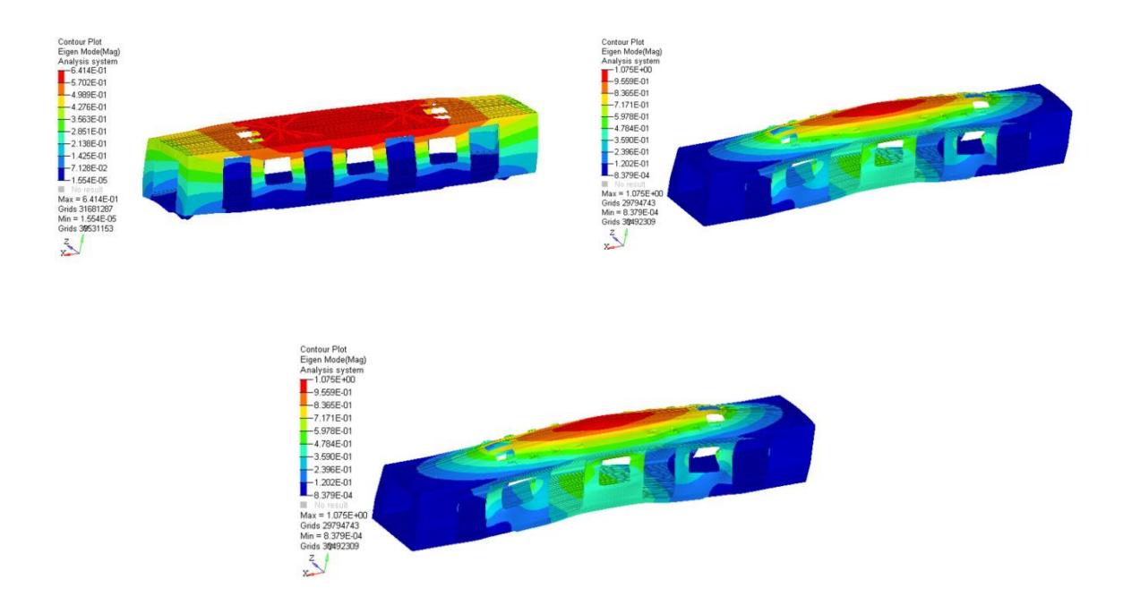
The modal analysis of the body structure after size optimization showed three mode shapes of the whole vehicle, that is, diamond, first-order sag bending, and first-order torsion, as shown in Figure 8.
Optimized modal analysis results of the rear rail vehicle body structure.
After optimization, the rhombic mode frequency of the rail vehicle body was 7.1 Hz, the first-order vertical bending mode frequency was 14.7Hz, and the first-order torsional mode frequency was 19.1Hz. According to EN12663:2010 – Railway applications – Structural requirements for railway vehicle bodies, the rail vehicle body structure should avoid the natural vibration frequency of the bogie. In general, the first-order vertical bending modal frequency of the rail vehicle body structure is required to be greater than 10 Hz and the first-order vertical bending modal frequency of the optimized car body is 14.7Hz. Therefore, the optimization results met the requirements of the standard to avoid the natural frequency of the bogie.
Optimization of the Structure and Size of the Rail Vehicle Body
Sensitivity Analysis for Vehicle Body Size Optimization
Due to the complexity of the rail vehicle body structure, the blind selection of design variables when optimizing the rail vehicle body structure will lead to failure of the optimized rail vehicle body structure performance to meet the design requirements and too many design variables will make the calculation not converge. Therefore, a sensitivity analysis for body size optimization is particularly important. In general, the finite difference method is used to analyze the sensitivity of a structure. The partial derivative of the response to the variable parameters is shown in Eq. (3):
\[\frac{\partial [K]}{\partial x_i} \{U\} + [K] \frac{\partial \{U\}}{\partial x_i} = \frac{\partial \{P\}}{\partial x_i}\] (3)
where is the size-optimized design variable. Then, the partial derivative of the displacement vector U is:
\[\frac{\partial \{U\}}{\partial x_i} = [K]^{-1} \left( \frac{\partial \{P\}}{\partial x_i} - \frac{\partial [K]}{\partial x_i} \{U\} \right) \tag{4}\] where {}/ is the sensitivity of the structural displacement to design variable . From Eq. (4), it can be seen that the calculation of the displacement sensitivity is transformed into a problem of the derivative of the value of the stiffness matrix [] against the variable , and the derivative of the load matrix [] from the variable can also be obtained. This translates to [], [] as the derivative of variable :
\[\frac{\partial [K]}{\partial x_i} = \frac{[K](X^{i+}) - [K](X^{i-})}{2\Delta x_i} \tag{5}\]
\[\frac{\partial\{P\}}{\partial x_i} = \frac{\{P\}(X^{i+}) - \{P\}(X^{i^-})}{2\Delta x_i} \tag{6}\]
Substituting Eqs. (5) and (6) into Eq. (4) gives the displacement sensitivity, {}/ . After calculating the displacement sensitivity, the partial derivative of the stress {} to design variable is obtained, which is the stress sensitivity of the structure. Its formula is:
\(\{\sigma\}^e = \{D\}\{B\}\{U\}^e = \{S\}\{U\}^e \tag{7}\)
where \(\{\sigma\}^e\) is denoted as the stress of the element; \(\{D\}\) is the relationship between stress and strain; \(\{B\}\) is the connection between strain and displacement; \(\{S\}\) should be the matrix; \(\{U\}^e\) is the displacement array of the element nodes. Finding the partial derivative of Eq. (7) for the design variable \(x_i\) gives the partial derivative of the element stress \(\{\sigma\}^e\) to \(x_i\) as:
\[\frac{\partial \{S\}}{\partial x_i} = \frac{\{S\}(X^{i+}) - \{S\}(X^{i-})}{2\Delta x_i} \tag{8}\]
After obtaining the stress sensitivity and displacement sensitivity, the relationship between the displacement and stress of the element is calculated as follows:
\[\begin{cases} \sigma_{k+1} = \sigma_k + \partial_{\sigma}/\partial x_i^k (x_i^{k+1} - x_i^k) \\\nu_{k+1} = \sigma_k + \partial_{u}/\partial x_i^k (x_i^{k+1} - x_i^k) \end{cases} \tag{9}\]
Sensitivity Analysis Results
Due to the large number of working conditions that needed to be calculated, the overcrowding compression condition was the most severe stress condition and the stress constraint was applied to the corresponding position under this working condition to analyze the sensitivity of the rail vehicle body structure. According to the stiffness evaluation standard of the rail vehicle body, the displacement constraint is applied to the middle position of the side beam of the rail vehicle body underframe under the condition of overloading. The maximum displacement of the rail vehicle body structure is controlled under the maximum operating condition. Taking the minimum weight of the car body as the objective function, the thickness of 30 components in the underframe structure, such as the underframe side beam, floor profile, underframe impact seat, and roof profile, was selected as the design variable for the sensitivity analysis. Table 3 lists the initial values and value ranges of variables.
Table 3 The initial value and value range of the vehicle body size optimization variable.
| Variable serial number | Initial value/mm | Lower limit/mm | Upper limit/mm |
|---|---|---|---|
| 1 | 6 | 4.1 | 8.1 |
| 2 | 10 | 6.5 | 13.5 |
| 3 | 5 | 3.5 | 7.5 |
| 4 | 11 | 7.5 | 14.5 |
| 5 | 5 | 3.5 | 7.5 |
| 6 | 2.5 | 1.4 | 3.8 |
| 7 | 2.5 | 1.4 | 3.8 |
| 8 | 2.5 | 1.4 | 3.8 |
| 9 | 2.5 | 1.4 | 3.8 |
| 10 | 2.5 | 1.4 | 3.8 |
| 11 | 2.5 | 1.4 | 3.8 |
| 12 | 2.5 | 1.4 | 3.8 |
| 13 | 2.5 | 1.4 | 3.8 |
| 14 | 2.5 | 1.4 | 3.8 |
| 15 | 2.5 | 1.4 | 3.8 |
| 16 | 2.5 | 1.4 | 3.8 |
| 17 | 2.5 | 1.4 | 3.8 |
| 18 | 2.5 | 1.4 | 3.8 |
| 19 | 2.5 | 1.4 | 3.8 |
| 20 | 3.5 | 2.2 | 5.5 |
| 21 | 3.5 | 2.2 | 5.5 |
| 22 | 3.5 | 2.2 | 5.5 |
| 23 | 3.5 | 2.2 | 5.5 |
| 24 | 3.5 | 2.2 | 5.5 |
| 25 | 3.5 | 2.2 | 5.5 |
| 26 | 3.5 | 2.2 | 5.5 |
| 27 | 4.0 | 2.5 | 6.5 |
| 28 | 15 | 10 | 20 |
| 29 | 2.8 | 1.5 | 3.5 |
| 30 | 3.0 | 1.5 | 3.5 |
The materials of the rail vehicle body consisted mainly of 6005A-T6 and 6082-T6,6000 series aluminum alloys, which belong to medium strength aluminum alloys. In order to improve the calculation accuracy and efficiency, the car body model was simplified reasonably. Due to the large size of the car body, the chamfer, fillet and round hole generated by the manufacturing process requirements can be omitted or processed as a right angle without affecting the strength calculation of the car body. When the non-load-bearing parts are applied to the load, they can be omitted because they have little influence on the strength and stiffness calculation of the rail vehicle body. For the shoulder, concave table, and various hole-like structures at the installation of the car body equipment, in order not to affect the overall strength of the car body, a smooth processing method was adopted. The material performance parameters of the rail vehicle body are shown in Table 4.
| Material type | Use place | Elastic modulus/GPa | Poisson ratio | Yield strength | ||
|---|---|---|---|---|---|---|
| Thickness of weldment/mm | Weld bead | |||||
| Aluminum floor, underframe | e≤5 | 125 | ||||
| 6005A-T6 | side beam, end beam, pillow beam, side door stand columns, side wall panels, roof plate ( including flat top ), roof edge beam, end wallboard, end door column, end beams and plates on doors wood | 70 | 0.33 | 5| 200 | 115 | |
| Coupler mounting seat, | e≤5 | 260 | ||||
| 6082-T6 | traction beam structure, bogie center pin mounting seat, end late | 70 | 0.33 | 5| 250 | 125 | |
Table 4 Performance parameters of metro body materials.
The appropriate part can be selected for optimization according to the sensitivity degree of each part, which reduces the amount of calculation and improves work efficiency. Therefore, when calculating the stress sensitivity and displacement sensitivity, the part of the rail vehicle body that is close to the yield limit of the material and the part that is the largest part of the car body deformation should be constrained to solve the sensitivity. When calculating the stress sensitivity, the area where the stress value is close to the yield limit is selected, such as the underframe traction beam, the door angle, the door angle under the end wall, etc. When calculating the displacement sensitivity, the middle position and the maximum displacement of the side beam of the underframe of the car body are selected according to the standard for constraint. The unit selection position and unit number are shown in Table 5.
| Select the structural location | Unit number |
|---|---|
| End wall under the door corner | 20767652 |
| Bottom frame edge beam connection | 18810275 |
| Underframe bottom plate | 19384057 |
| Side wall corner | 20691802 |
| Underframe side beam | 28413267 |
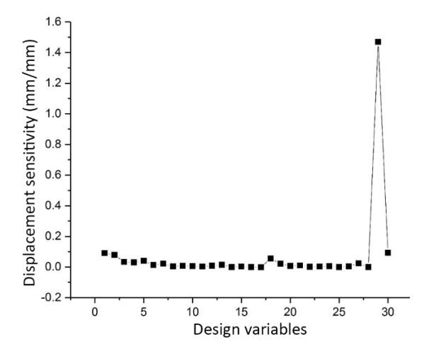
As shown in Figure 9, the absolute value of sensitivity value of the stress at the junction of the underframe side beam to the serial numbers 1, 2, 3, 4, 29, and 30 was obtained by sensitivity calculation. The absolute value of the sensitivity value of the underframe floor to the serial number 1, 2, 3, 4, 27, 29 was larger, the stress at the window angle of the rail vehicle body side wall structure was greater than the absolute value of the sensitivity value of serial number 1, 2, 3, 4, 5, 27, 29, and the absolute value of the sensitivity value of the stress at the underframe side beam of the rail vehicle body structure was larger. When the sensitivity is greater, the change in the size of the design variable has a more obvious impact on the stress value of the rail vehicle body structure. When carrying out the displacement sensitivity calculation, the middle position of the side beam of the rail vehicle body underframe was selected according to the standard to be constrained. After the displacement sensitivity calculation, the displacement change of the side beam of the rail vehicle body underframe was more sensitive to the design variables 1, 2, 18, 29, 30. The displacement sensitivity line drawn is shown in Figure 10.
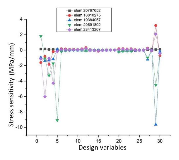
The sensitivity of the design variable to stress.
The sensitivity of the design variable to displacement.
Through the above calculation of the sensitivity of the rail vehicle body, the optimization design has to ensure the static strength and stiffness of the rail vehicle body as far as possible. Under the same condition, the chassis structure was optimized to reduce the quality of the chassis to achieve the purpose of lightweighting the train.
Body Size Optimization and Result Analysis
Under the condition of overworking conditions, the stress, displacement, and first-order vertical bending frequency of the rail vehicle body structure were taken as constraints and the minimum mass of the car body structure was taken as the objective function to optimize the size of the 21 groups of plates of the underframe. After four iterative calculations, the mass of the optimized front underframe components was 3.51 t, the optimized component mass was 2.74 t, the weight reduction ratio was 21.6% The optimal parameter combination of the lightweight design of the vehicle body is shown in Table 6.
Table 6 Variable position and corresponding dimension parameters.
Variable
| Variable serial number | Initial value/mm | Lower limit/mm | Upper limit/mm | Size after iteration/ mm |
|---|---|---|---|---|
| 1 | 2.5 | 1.4 | 3.8 | 1.4 |
| 2 | 2.5 | 1.4 | 3.8 | 1.6 |
| 3 | 2.5 | 1.4 | 3.8 | 1.6 |
| 4 | 2.5 | 1.4 | 3.8 | 1.5 |
| 5 | 2.5 | 1.4 | 3.8 | 1.4 |
| 6 | 2.5 | 1.4 | 3.8 | 1.4 |
| 7 | 2.5 | 1.4 | 3.8 | 1.5 |
| 8 | 2.5 | 1.4 | 3.8 | 1.5 |
| 9 | 2.5 | 1.4 | 3.8 | 1.4 |
| 10 | 2.5 | 1.4 | 3.8 | 1.4 |
| 11 | 2.5 | 1.4 | 3.8 | 1.4 |
| 12 | 2.5 | 1.4 | 3.8 | 1.4 |
| 13 | 2.5 | 1.4 | 3.8 | 1.4 |
| 14 | 2.5 | 1.4 | 3.8 | 1.4 |
| 15 | 3.5 | 2.2 | 5.5 | 2.2 |
| 16 | 3.5 | 2.2 | 5.5 | 2.2 |
| 17 | 3.5 | 2.2 | 5.5 | 2.2 |
| 18 | 3.5 | 2.2 | 5.5 | 2.2 |
| 19 | 3.5 | 2.2 | 5.5 | 2.2 |
| 20 | 3.5 | 2.2 | 5.5 | 3.5 |
| 21 | 3.5 | 2.2 | 5.5 | 2.2 |
Topology Optimization and Size Optimization Vehicle Body Performance Analysis
As shown in Figure 11 (a), under the condition of overcrowding, the maximum stress value of the rail vehicle body structure was 43.5 MPa, which appeared at the welding place of the reinforcing plate of the underframe sleeper beam. Figure 11 (b) is the displacement contour diagram of the rail vehicle body structure under the condition of overcrowding conditions. The vertical displacement at the lower side beam of the underframe was 3.39 mm and the considerable bending stiffness of the rail vehicle body structure could be obtained, which was 1.35 × 10⁹ N/m2 , which meets the structural stiffness requirements.
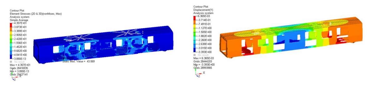
(a) Stress contour diagram (b) Dynamic displacement cloud diagram
Analysis of the structural performance of the vehicle body under the condition of overcrowding.
Figure 12(a) shows the maximum operating load under this condition, in which the maximum stress of the rail vehicle body unit was 80.0 MPa, and the maximum stress occurred at the upper door angle, where the stress value increased slightly compared with before optimization. The maximum equivalent stress of each main component of the rail vehicle body increased slightly, but it was less than the allowable stress of the material. The vertical displacement of the rail vehicle body is shown in Figure 12(b). Under the action of the maximum operating condition, it can be seen from the displacement contour diagram of the whole vehicle that the maximum displacement in the vertical direction of the vehicle was 10.97 mm, which is slightly increased compared with before optimization but still meets the requirement of less than 12.6mm.
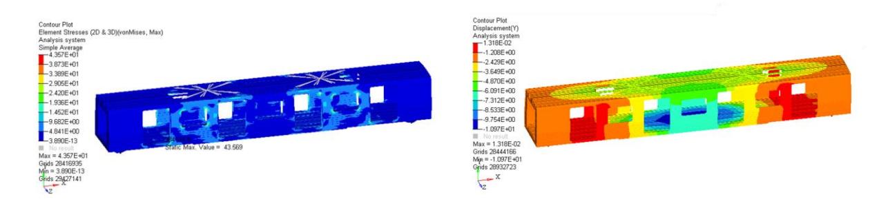
Analysis of structural performance of vehicle body under maximum operating load conditions.
The modal analysis of the body structure after size optimization showed three mode shapes of the whole vehicle, that is, diamond, first-order vertical bending, and first-order torsion, as shown in Figure 13. After optimization, the rhombic mode frequency of the rail vehicle body was 7.13 Hz, the first-order vertical bending mode frequency was 14.8Hz, and the first-order torsional mode frequency was 19.34Hz, which is increased while reducing the weight.
(a) Stress contour diagram (b) Dynamic displacement cloud diagram
Modal analysis results of the rail vehicle body structure after size optimization.
Conclusions
In this study, the intermediate car body of a certain type of aluminum alloy rail vehicle was taken as the research object. The topology optimization method was used on the cross-section structure of the rail vehicle body. It was found that under the action of various working conditions, the rail vehicle body displayed the phenomenon of local stress concentration, which mainly appeared in the window corner, passenger compartment door angle, end wall door corner, and the welding place with the pillow slow structure, which had good consistency compared with the results of the general rail vehicle body static strength test. However, based on the weighted compromise programming method, considering different wind load conditions, the topology of the roof and side wall cross-section structures was optimized and finally a new cross-section rib plate layout was obtained. The mass of the cross-section rib plate was 0.585 t and the weight reduction ratio was 4.47% compared with that before optimization. Under the premise of satisfying the requirements of mode, stiffness, and strength, the moment of inertia of the cross-sectional graphic of the optimized rail vehicle body on the coordinate axis was slightly reduced compared with the previous one. Based on the sensitivity analysis theory, the material utilization rate and stiffness of the new structure of the rail vehicle body were improved, the weight of the optimized rail vehicle body was reduced by 0.77 t, the weight reduction ratio was 21.6%, and the strength, stiffness, and modal frequency of the rail vehicle body met the design requirements, which realized the purpose of lightweighting the rail vehicle body.
Acknowledgements
This research was funded by National Natural Science Foundation of China (52375169), Liaoning Province Science and Technology Program(2022JH2/101300228), Liaoning Province Doctoral Research Foundation Project (2022-BS-260), Liaoning Provincial Department of Education Scientific Research Project (LJKZ0479) and Liaoning Provincial Department of Transportation Research Project (202148).
Compliance with Ethics Guidelines
The authors declare that they have no conflict of interest or financial conflicts to disclose.
This article does not contain any studies with human or animal subjects performed by any of the authors.