
Introduction
Wind energy extraction capabilities and noise emissions are essential considerations in the design of a wind turbine. Much effort has been made to increase the capability of wind turbines to produce power. Airfoil selection and redesign have been carried out to increase profile efficiency and reduce noise emissions [1-4]. Horizontal shaft wind turbine blades have been modified to increase the annual power and energy production [5-7]. Diffuser augmentation on the horizontal-axis wind turbine rotor is intended to improve the airflow that the rotor is exposed, so that the turbine efficiency is higher than without diffuser support [8-11]. The present article focuses on the effect of tip blade modification on aerodynamic rotor performance and its generated noise. The modified tip blade is limited to two turns of the swept blade and an anhedral angle. The tips were changed to modify the tip vortex shedding, which influences blade performance and noise generation.
Noise is a by-product of wind power generation. This noise needs to be controlled for the safety and comfort of humans and the surrounding environment. Wind turbine user countries set noise limits based on operating time, land use, and wind speed. For residential areas, the maximum noise is limited to 40 dB(A) [12]. The noise generated by wind turbines is a broadband type that contains a wide frequency band without large spectral peaks [13]. Low-frequency sound can spread farther than high-frequency sound through the atmosphere [14, 15], so low-frequency sound with high noise levels deserves attention in the design of wind turbine blades.
Wind turbine noise is produced by vortices in the atmosphere and vortices released by the wind turbine blades. Large vortices yield low-frequency noise, while small vortices produce high-frequency noise [16]. The production of vortices by wind turbine blades has a mechanism similar to that of airplane wings and helicopter propellers. Adding a winglet on
the wing can reduce the size of the tip vortex, thereby reducing drag and saving fuel consumption [17]. The sweep on a blade has a function similarly to the sweep on a delta wing. Delta wings with a high swepep angle or low aspect ratio can generate rolled-up vortices [18, 19]. Meanwhile, modification of the tip of helicopter propeller blades is used to reduce noise by breaking the vortex at the end into a smaller size [20]. In horizontal axis wind turbines, blade tip shape modification involving sweep, winglet, and dihedral angles is focused on improving rotor performance [21], while blade tip modification meant to reduce noise requires further study.
This article presents an investigation of the effects of improved wind turbine designs on aerodynamic performance and noise emission. The aerodynamic performance and sound pressure level produced by small wind turbines were characterized based on experimental data. Three blade models were tested in the experiment. A blade following the Schmitz distribution for chord length and twist angle were used as the basic planform and the two other samples were blades with tip modification of the basic blade. The aerodynamic performances were tested using the IEC 61400-12-1 standard method, and the noise was measured based on the IEC 61400-11 standard.
Methods
Samples
The wind turbine designs in this experiment were based on the field conditions of the test site, with an annual average wind speed (,) of 4.5 m/s. The wind speed for rated output power ideally ranges from 1.5 to 2 times the average wind speed [22]. In this study, three types of blades were tested, i.e., a basic blade and two modified blades. The basic blade rotor had straight blades designed for rated wind speeds (,) of 9 m/s. The number of blades () was three. The blades had a tip speed ratio (λD) of 5.24, which is the lowest tip speed ratio design for a rotor with three blades [23]. This ratio makes the blades wide and produces airfoil sections with high angles of attack at the start, therefore, the rotor had a high rate of torque increase. The basic blade and modified blade 1 were designed to build a wind turbine rotor with a radius () of 1.05 m, while the rotor with modified blade 2 had a radius of 1.4 m. Airfoil NACA 4412 was chosen as the cross-section because it has a high gliding ratio.
The distribution of chord length () and pitch angle () were designed following the Schmitz distribution, calculated using Eqs. (1) and (2) [24]. The designed lift coefficient (,) and the angle of attack () were determined based on the Reynolds number (), calculated from the relative wind speed ( ) at the rated speed, where the axial interference factor () was determined at the ideal value of 1/3. The distribution of both the length of the chords and the pitch angles are shown in Figure 1(a).
Modified blade 1 was designed based on the basic blade design, where, at a radial distance () between 0.9 and , the blade shape was modified to have a double sweep and an anhedral angle. The first turn had an angle of 12°, while the second turn had an angle of 61°. The anhedral angle was formed from 0.9 with an angle of 15°. The distribution of the chord lengths and the pitch angles are shown in Figure 1(a), and the detailed geometries are presented in Figure 1(b). The modified blade 2 design was also based on that of the basic blade. The blade tip had two turns. The first turn had an angle of 32°, while the second turn had an angle of 72°. The blade tip had an anhedral angle of 15°. The detailed geometries of the blades are presented in Figures 1(a) and 1(c).
The rotors were analyzed by the open-source software Q-Blade to predict their maximum coefficient of power. The rotor with basic blades had a maximum coefficient of power of 0.474, the rotor with modified blade 1 had a maximum coefficient of power of 0.475, and the rotor with modified blade 2 had a maximum coefficient of power of 0.484.
\[c(r) = \frac{1}{B} \frac{16\pi r}{c_{L,D}} \sin^2 \left\{ \frac{1}{3} \arctan \left( \frac{R}{\lambda_D r} \right) \right\}\] (1)
\[\beta(r) = \frac{2}{3} \arctan \frac{R}{\lambda_D r} - \alpha_D \tag{2}\]
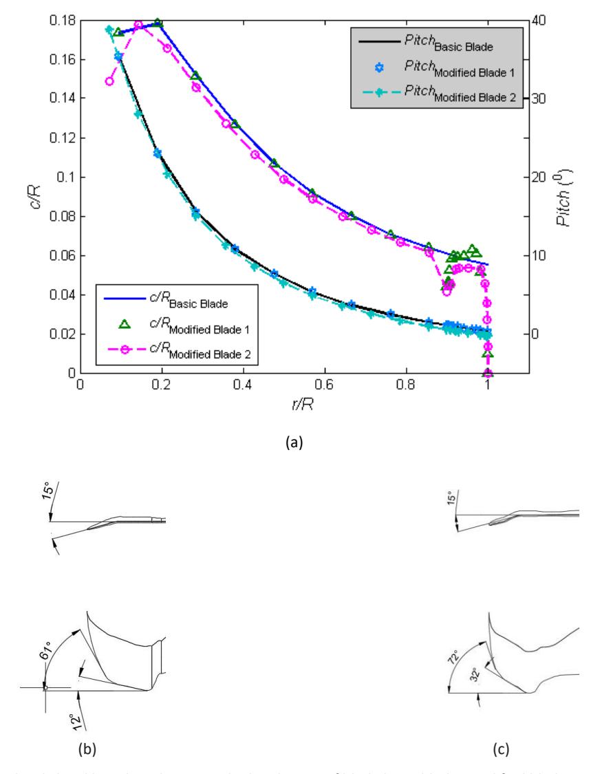
Figure 1 (a) Normalized chord length and twist angle distribution of blade basic blade, modified blade 1, and modified blade 2; (b) tip of modified blade 1; (c) tip of modified blade 2.
Aerodynamic Performance Measurement
The test method for measuring aerodynamic performance was based on the IEC 61400-12-1 [25]. The turbines were attached to a 12-volt DC generator system. The generator had a rated power of 400 watts. The rotor was mounted onto a tower with an elevation of 10 meters. The distance from the meteorological mast (a) to the wind turbine was about 8 m (Figure 2). The mast had the same height as the rotor. The power generated by the turbine was directed to a dummy load system, consisting of a series of light bulbs whose input voltage was regulated using a relay system. The data containing time, generator voltage, generated electric current, power, temperature, humidity, air pressure, and wind speed were recorded on an SD card every three seconds. The bins method determined the power curve with a bin speed of 0.5 m/s for every data set by Eqs. (3) and (4). The rotors' performance was measured on the shoreline at the geographic position of 7°59'20.8'S, 110°13'16.2'E. The sum of recorded data was more than 500 points to cover all ranges of wind speeds in the field and the trends of the measured parameters.
\[V_i = \frac{1}{N} \sum_{j=1}^{N} V_{n,i,j} \tag{3}\]
\[P_i = \frac{1}{N} \sum_{j=1}^{N} P_{n,i,j} \tag{4}\]
Noise Measurement
Noise measurements were conducted simultaneously with the power measurements. The instrument setup and data processing of the measurements were based on IEC 61400-11 standard [26]. The turbine and environmental noise were captured using a microphone with an effective specification range of 10,000 Hz. The microphone was placed on a plywood board with a thickness of 12 mm and then placed on the ground. The distance between the tower and the microphone (b) was about 11 m behind the tested turbine (Figure 2). Noise data was recorded every three seconds on a micro SD at each 1/3 octave center frequency from 12.5 Hz to 10,000 Hz. Each data point was the average value of the noise measurement results in one minute at the related center frequency of 1/3 octave. Measurements were made within ±0.5 at each integer wind speed. The measurement data at each integer wind speed was approximated using polynomial regression of order 4 in the form of equation 4 + 3 + 2 + + , where is the associated frequency [14]. The background noise corrected rotor noise ( ) was calculated from the measurement results of background noise () and rotor noise (+) using Eq. (5). The function value of the polynomial is the A-weighted sound pressure level (SPL) value used to determine the background noise corrected SPL (,,). Then, apparent sound (,) was determined using Eq. [6]. 1 in the equation is the distance from the rotor center to the microphone and 0 is a reference area of 1 m2 .
\[L_{s} = 10lg \left( 10^{(0.1L_{s+n})} - 10^{(0.1L_{n})} \right) (5)\] \[L_{WA,k} = L_{Aeq,c,k} - 6 + 10lg \left( \frac{4\pi R_{1}^{2}}{S_{0}} \right)\] (6)
Figure 2 Experimental setup of power generation and noise measurements: (1) wind speed sensor and wind direction sensor; (2) wind turbine rotor, power generator, dummy load, and relay; (3) microphone; (4) data logger, voltage meter, ampere meter, temperature sensor, humidity sensor, and air pressure sensor.
Results and Discussion
Aerodynamic Performance
The performance measurement results of the turbines with the basic blade, modified blade 1, and modified blade 2 are shown graphically in Figures 3 to 5. The figures show the effect of modification of modified blade 1 and modified blade 2 on the performance of the rotors. The dashed blue lines in Figures 3(a), 4(a), and 5(a) represent the theoretical power that could be produced by the rotors, while the continuous magenta lines depict the fitted data with a third-order polynomial. Vertical green lines in Figures 3(b) and (d) to 5(b) and (d) indicate the designed tip speed ratios.
The power generation characteristics of the basic blade rotor are represented in Figure 3(a). The rotor produced less power than the theoretical power at a wind speed above 2.5 m/s, whereas below this speed, the power generated was greater than the theoretical value. This discrepancy can be attributed to the inertia of the rotor rotating at high speed. As the wind speed increases, the produced power deviates further from the theoretical value. At a wind speed of 9 m/s, the basic blade rotor is capable of producing power ranging from 150 to 200 watts (Figure 3(a)). Meanwhile, the modified blade 1 rotor could only produce power ranging from 100 to 150 watts (Figures 4(a)). The rotor with modified
blade 2 could produce higher power than the other two rotors, ranging from 200 to 250 watts (Figures 4(a)), as it had a larger sweep area than the others. Using modified blade 1 resulted in a 23% power decrease and using modified blade 2 resulted in an 80% power increase at wind speeds above 5 m/s. These finding align with the results of a research on wind turbines in wind tunnels, where a blade designed at a tip speed ratio of 4.7 had decreased power production when the blade tip sweep was at an angle of less than 30°, and an anhedral angle of 15° was added [27]. Although it did not indicate whether the modification involved a high-angle sweep, the power production increased significantly.
The rotational characteristics in terms of the tip speed ratio at various wind speeds for the basic blade are shown in Figure 3(b). The vertical line in the graph indicates the design value of 5.24 for the tip speed ratio. The data to the left of the line indicate that the rotor rotated at a speed lower than the designed speed, while the data to the right indicate rotor speeds higher than the designed speed. The basic blade needed a wind speed of about 4 m/s to start rotating, as the rotor had no data under the speed to the left of the designed tip speed ratio. This is common for small wind turbines, as they lack a pitch control mechanism. At low wind speeds, the blades experience a low Reynolds number, resulting in a reduced lift force. After starting, the turbine can rotate at wind speed below the designed tip speed ratio. Under these circumstances, the rotor rotation creates a relative wind speed vector at an angle of attack that generates higher lift compared to when the rotor is starting, thereby reducing stall condition on the blade surface. In this condition, the inertia of the rotor plays a role in maintaining rotation at low wind speeds. At wind speeds above 7 m/s, the rotor could not reach the designed tip speed ratio. The slower rotor speed indicates the formation of stalls on the surface of the blade, resulting in inefficient conversion of wind energy at these wind speeds. As shown in Figure 3(c), the higher the wind speed, the lower the coefficient of power. The basic blade resulted in a coefficient of performance ranging from 0.05 to 0.25 at the designed tip speed ratio (Figure 3(d)). This value is typically the maximum coefficient of power observed in small wind turbines, which usually ranges from 0.2 to 0.3 [22]. The designed tip ratios achieved by the rotor when wind speeds were between 4 m/s and 7 m/s are presented in Figure 3(b).
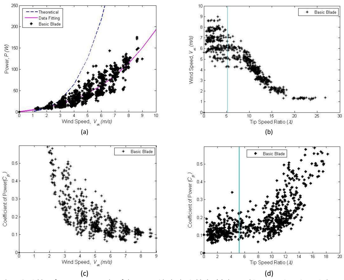
Figure 3 Field performance test results of the rotor with the basic blade: (a) the resulting power in various wind speeds; (b) rotational behavior of the rotor in various wind speeds; (c) coefficient of power of the rotor as a function of wind speed; (d) coefficient of power of the rotor as a function of tip speed ratio.
The aerodynamic performance of modified blade 1 are shown in Figures 4(a) to 4(d). The rotor with modified blade 1 initiated rotation at a wind speed of approximately 3 m/s, as shown in Figure 4(b), where tip speed ratios approaching zero were observed. This shows that this blade had better starting behavior than the basic blade. The blade could sustain rotor operation up to wind speeds of 9 m/s, approaching the designed tip speed ratio. However, it tended to slow down, as evidenced by the data collected to the left of the designed tip speed ratio (Figure 4(b)), indicating stall formation on the blade surface. The decreased tip ratio led to a decline in coefficient of performance at higher wind speeds (Figure 4(c)). The blade tended to produce a coefficient of performance ranging from 0.05 to 0.20 at a designed tip speed ratio that is lower than that produced by the basic blade (Figure 4(d).
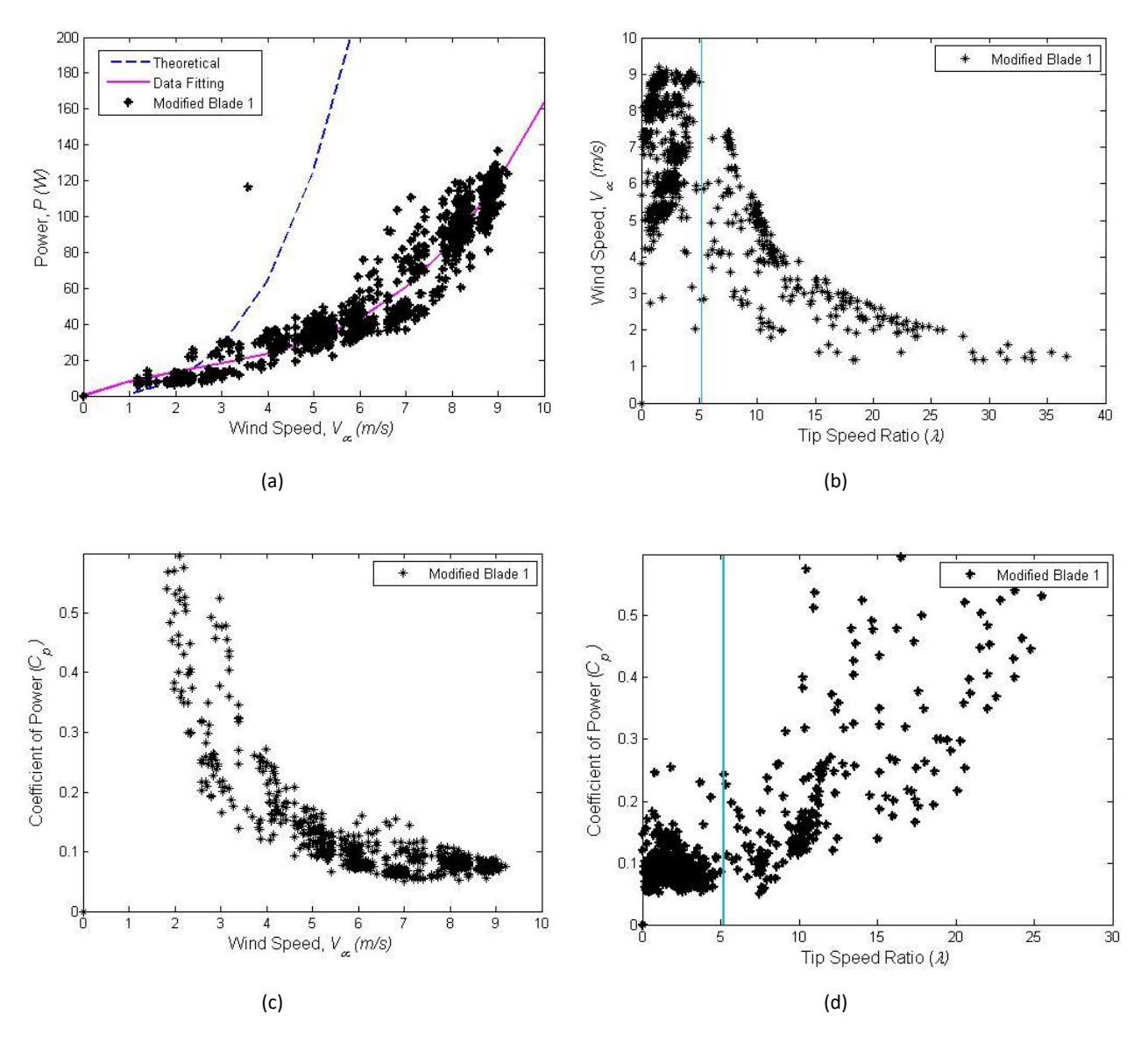
Figure 4 Field performance test results of rotor with modified blade 1: (a) the resulting power at various wind speeds; (b) rotational behavior of the rotor at various wind speeds; (c) coefficient of power of the rotor as a function of wind speed; (d) coefficient of power of the rotor as a function of tip speed ratio.
The aerodynamic performance of modified blade 2 is depicted in Figures 5(a) to 5(d). The blade could initiate rotation at a wind speed of about 1 m/s. This is lower than the wind speed that was needed for the rotor with modified blade 1 to start. This shows that modified blade 2 has better starting behavior than the basic blade and modified blade 1. The inertia of modified blade 2 influenced the rotational speed and power production at wind speeds lower than 3 m/s, as it produced power higher than its theoretical value. The blade could operate effectively at wind speeds exceeding 10 m/s and at approximately the designed tip speed ratio (Figure 5(b)), indicating reduced stall formation compared to the basic blade. This occurred even at higher tip speed ratios than those specified in its design. Even at higher wind speeds, the rotor produced a lower coefficient of power (Figure 5(c)). The rotor could generate a coefficient of power ranging from 0.05 to 0.15, lower than that of the basic blade, while maintaining the designed tip speed ratio (Figure 5(d)). The designed tip ratio achieved by the rotor when wind speeds were between 5 m/s to 8 m/s are shown in (Figure 3(b)).
The sweep geometry in fluid flow can generate rolled-up vortices at the right and left edges, which create a stall delay. The aerodynamic performance difference observed from the tip modification of the blades and their angles is attributed to the behavior of fluid flow past the swept tips. The high sweep angle at the tip of modified blade 2 had the strongest effect on starting the rotor, followed by modified blade 1 and the basic blade. Additionally, this geometry helps the rotor to operate at the designed tip speed ratio during higher wind speeds.
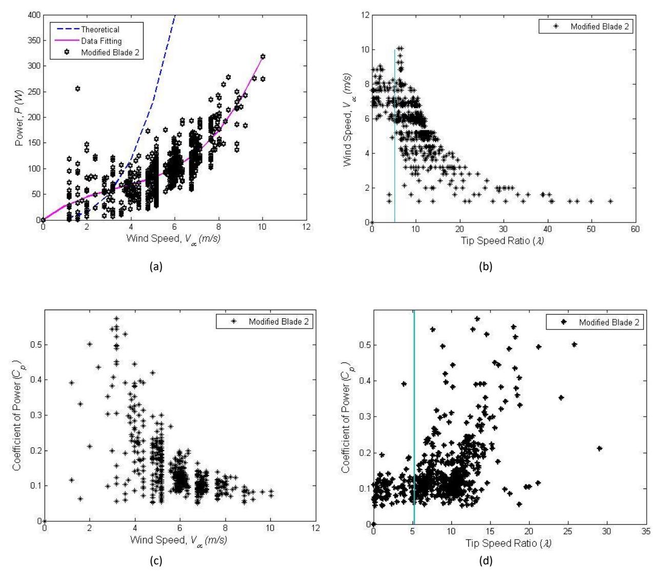
Figure 5 Field performance test results of the rotor with modified blade 2: (a) the resulting power of the rotor at various wind speeds; (b) rotational behavior of the rotor at various wind speeds; (c) coefficient of power of the rotor as a function of wind speed; (d) coefficient of power of the rotor as a function of tip speed ratio.
Noise Characteristic
The noise measurement results for the background, the basic blade rotor, the modified blade 1 rotor, and the modified blade 2 rotor are presented in Figures 6 to 8. Table 1 lists the constant values for each type of measurement. The 2 values of the background decreased slightly with the basic blade rotor installed in the airflow. This shows that the blade design using a of 5.24 resulted in a stable output. This stability was slightly increased for modified blade 1 at integer wind speeds of 6 and 8 m/s but decreased at integer wind speeds of 7, 9, and 10 m/s. The modified blade 2 rotor had the lowest 2 at integer wind speeds higher than 7 m/s, as the rotor produced the most scattered noise data.
| Integer wind speed (m/s) | a | b | С | d | е | \(R^2\) |
|---|---|---|---|---|---|---|
| Background | ||||||
| 6 | 4e-14 | -9e-10 | 7e-6 | -0.0221 | 55.582 | 0.9311 |
| 7 | 4e-14 | -1e-9 | 8e-6 | -0.0240 | 55.699 | 0.9285 |
| 8 | 5e-14 | -1e-9 | 8e-6 | -0.0256 | 55.738 | 0.9367 |
| 9 | 4e-14 | -1e-9 | 8e-6 | -0.0237 | 55.411 | 0.9213 |
| 10 | 3e-14 | -8e-10 | 7e-6 | -0.0224 | 55.335 | 0.9240 |
| Basic blade | ||||||
| 6 | 3e-14 | -8e-10 | 6e-6 | -0.0199 | 54.783 | 0.9280 |
| 7 | 3e-14 | -8e-9 | 6e-6 | -0.0205 | 54.737 | 0.9314 |
| 8 | 3e-14 | -8e-10 | 6e-6 | -0.0187 | 54.085 | 0.8454 |
| 9 | 3e-14 | -8e-10 | 6e-6 | -0.0208 | 54.924 | 0.9242 |
| 10 | 3e-14 | -8E-10 | 6e-6 | -0.0216 | 55.104 | 0.9190 |
| Modified blade 1 | ||||||
| 6 | 4e-14 | -1e-9 | 7e-6 | -0.0196 | 51.094 | 0.9378 |
| 7 | 2e-14 | -6e-10 | 6e-6 | -0.0199 | 53.670 | 0.8918 |
| 8 | 2e-14 | -5e-10 | 5e-6 | -0.0187 | 53.951 | 0.8936 |
| 9 | 4e-14 | -1e-9 | 7e-6 | -0.0193 | 52.459 | 0.8095 |
| 10 | 1e-13 | -2e-0 | 1e-5 | -0.0246 | 53.658 | 0.9161 |
| Modified blade 2 | ||||||
| 7 | -7e-14 | 1e-9 | -6e-6 | 0.0115 | 47.392 | 0.9786 |
| 8 | -6e-14 | 9e-10 | -4e-6 | 0.0065 | 48.369 | 0.7647 |
| 9 | -7e-14 | 1e-9 | -5e-6 | 0.0072 | 48.188 | 0.7350 |
| 10 | -6e-14 | 8e-10 | -3e-6 | 0.0050 | 49.993 | 0.7833 |
Table 1 Polynomial constants of noise data measurements.
Installing the rotor in the field caused the background noise to change. Installation of the basic blade rotor resulted in a slight decrease in SPL at low to medium frequencies, while at high frequencies, SPL increased slightly (Figures 6(a) to 6(d)). At an integer wind speed of 10 m/s, the basic blade did not produce a significant change in SPL (Figure 6 (e)). Installation of the modified blade 1 rotor led to a larger SPL change than the basic blade rotor (Figures 7(a) to 7(e)). The tip modification of the modified blade 2 rotor resulted in different noise production characteristics from the basic blade and modified blade 1 rotors. Modified blade 2 produced less noise than the basic blade and modified blade 1 at frequencies below 200 Hz and produced higher noise at frequencies above 200 Hz to 10,000 Hz (Figures 8(a) to 8(d)). Figure 9 shows the difference in noise production from the basic blade, modified blade 1, and modified blade 2 in the form of the background noise corrected SPL (\(L_{Aeq.c.8}\)) and apparent sound (\(L_{WA.8}\))) at an integer speed of 8 m/s. Background corrected noise at frequencies below 30 Hz followed the background noise, while for frequencies above 30 Hz, it followed a background correction mechanism and the determination of the apparent sound value. The differences showed that the modification of the blade tip affected the airflow on the blade surface. Modified blade 2 decreased the SPL in the low-frequency range while increasing it in the high-frequency range. Although the modified blade 2 rotor had the highest power production, it also generated higher noise than the basic blade rotor at frequencies higher than 200 Hz
The alteration in noise level pattern due to blade planform modification is a significant result of this study. Noise absorption by the atmosphere is not only influenced by inverse square loss term but also by relative humidity and sound frequency. The higher the relative humidity, the lower the attenuation constant; conversely, the higher the frequency, the higher the attenuation constant [28]. The combination of a high angle of complex sweep and the anhedral angle of modified blade 2 resulted in higher power production compared to both the basic blade and modified blade 1. Nevertheless, modified blade 2 produced more noise than the other two at frequencies higher than 200 Hz. The change in noise production is a consequence of utilizing the modified blade 2 tip. Despite the higher noise levels, the benefit of the modified blade 2 lies in the fact that the majority of the noise is at high frequencies, and this high-frequency noise is expected to be significantly absorbed by the atmosphere.
In previous studies, the sweep angle, the anhedral angle, and a right winglet improved the performance of wind turbine blades [5]. These modifications can also reduce the size of the tip vortex of an aircraft wing and split the tip vortex of a helicopter propeller [20]. In this study, tip modification provided an effect similar to that of a helicopter propeller, reducing the size of the tip vortex as indicated by noise in high frequency ranges.
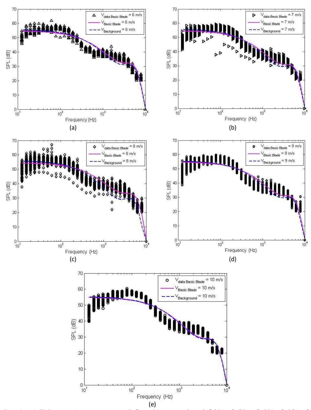
Figure 6 Basic blade rotor noise measurement results for each integer wind speed of: (a) 6 m/s, (b) 7 m/s, (c) 8 m/s, (d) 9 m/s, and (e) 10 m/s.
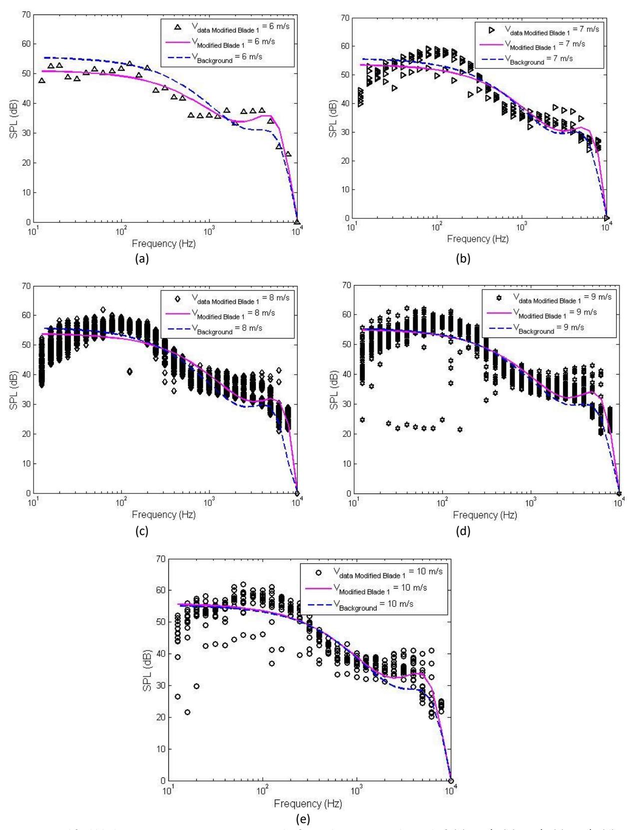
Figure 7 Modified blade 1 rotor noise measurement results for each integer wind speed of: (a) 6 m/s, (b) 7 m/s, (c) 8 m/s, (d) 9 m/s, and (e) 10 m/s.
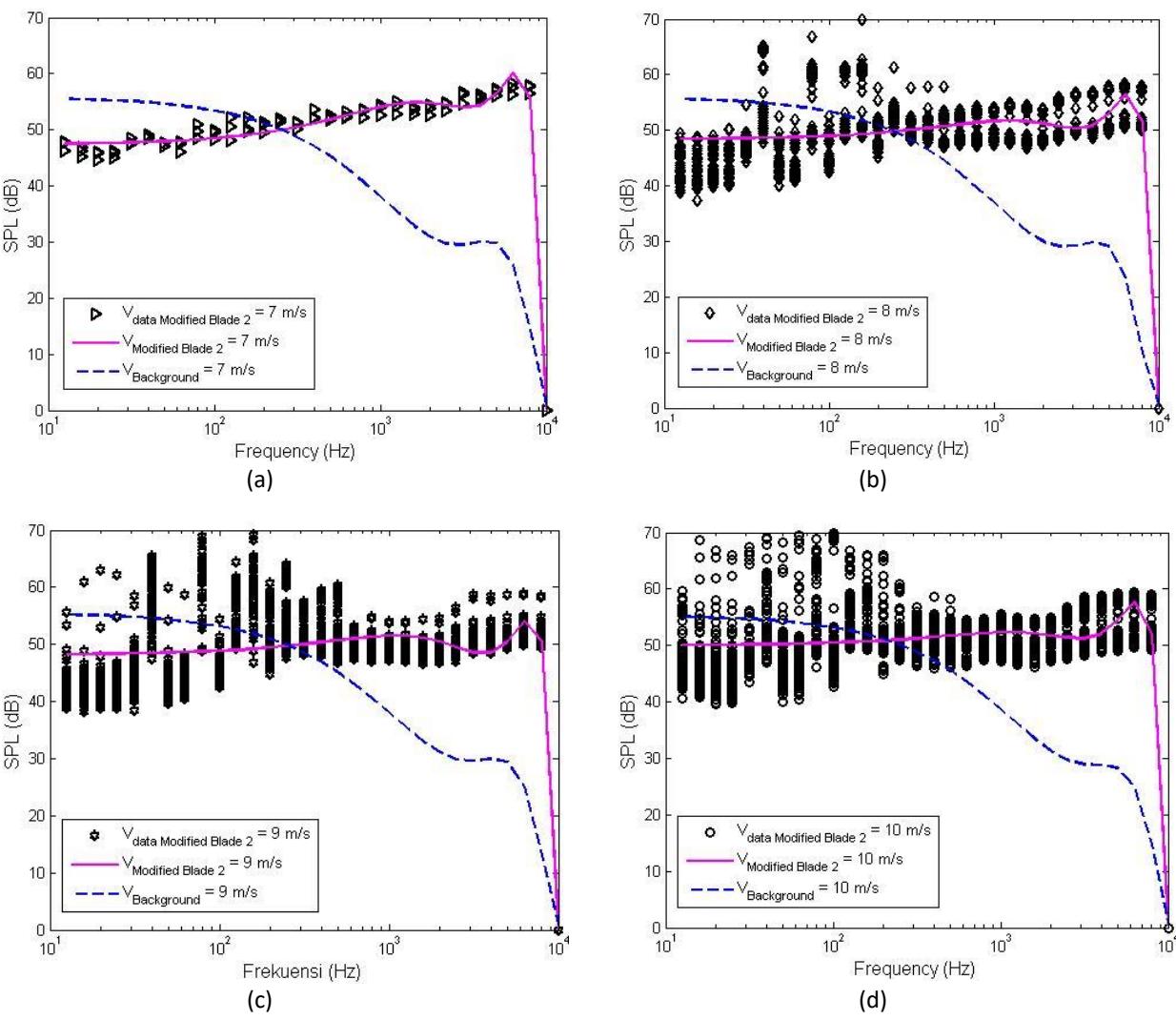
Figure 8 Modified blade 2 rotor noise measurement results for each integer wind speed of: (a) 7 m/s, (b) 8 m/s, (c) 9 m/s, and (d) 10 m/s.
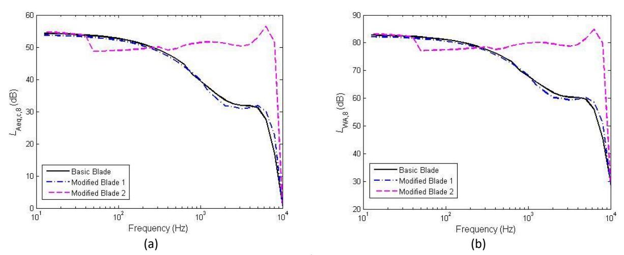
Figure 9 Sound level at an integer wind speed of 8 m/s: (a) background corrected sound, and (b) apparent sound.
Conclusion
An experiment was conducted to study the aerodynamic performance and noise levels of three small-scale horizontal axis wind turbines. The rotor blades were modified to have a double sweep and an anhedral angle and were tested in field environmental conditions.
In conclusion, rotor blades with a high-angle tip sweep require lower wind speed to start and can maintain the rotor operating at the designed tip speed ratio at higher wind speeds. However, they have a lower maximum coefficient of power compared to blades with a low-angle sweep and basic blades.
Blades with a high-angle sweep also reduce noise at low frequencies, which can travel far through the atmosphere. However, this reduction in low-frequency noise is accompanied by an increase in noise at high frequencies. Noise at high frequencies is more easily absorbed by the atmosphere, preventing its propagation over longer distances.
Compliance with ethics guidelines
The authors declare that they have no conflict of interest or financial conflicts to disclose.
This article does not contain any studies with human or animal subjects performed by any of the authors.