
Introduction
Cutting tools are used in various operations, such as drilling, milling, turning, grinding, and so on. The speed of the cutting tool depends on its level of efficiency. A high-quality cutting tool has high yield strength at cutting temperature, high fracture toughness, high wear resistance, high fatigue resistance, high heat conductivity, and good oxidation resistance. Several different materials are used for cutting tools employed in industry, such as high-speed steel (HSS), ceramics, and cemented carbides. Ceramic tools are fundamental to high-speed cutting (HSC) materials because they have three to ten times more resistance than sintered carbide materials and can also operate at several times their highest cutting speed [1]. The number of industries that use cemented carbide cutting tools is growing because of its high hardness and cost savings when compared with ceramic or diamond cutting tools [2]. Cemented carbide cutting tools have a very high level of hardness, which allows them to operate at temperatures as high as 1,000 ℃ [3]. In addition, they can operate at a cutting speed range between 60 and 200 m/min.
Each cutting tool material also has specific characteristics, such as hardness, strength, melting point, and chemical inertness at high cutting temperatures [4]. To smoothen the cutting process, the hardness of the cutting tool material should be at least 1.5 times the hardness of the working material [5]. Due to their exceptional wear resistance and high strength and hardness, cemented carbides are often used for tools for cutting, forming, mining, and structural elements. According to [6], grain formation and defects affect the mechanical properties of cemented carbides. The bending strength increases as the size of the defect decreases, the fracture strength increases as the mean free path in the binding phase increases, and the hardness increases as the contiguity increases. The introduction of coating processes using hard coatings such as TiC, TiN, Ti (C, N) on the surface of the cemented carbide further improves the performance of the cutting tool. Coated CVD coatings such as Al2O3, Ti(C,N) and (Ti,Al) have proven highly effective for use in applications where high oxidation and wear resistance, and low shear coefficients are required [7]. Cemented carbides based on tungsten carbide and cobalt are commonly produced by a powder metallurgy route such as liquid phase sintering. Cobalt is the most used metal as the binder, followed by nickel and iron. The incredible wettability of cobalt to cemented carbide, as well as its superior mechanical properties, are the basis for its use. Until the temperature
reaches 417 ℃, pure cobalt will be stable in hexagonal modifications, but at higher temperatures, cubic modifications exist [7]. Structures of high-temperature cubic modifications are maintained during sintering, when the fasteners become solid.
The amount of wear rate of cemented carbides depends on the cutting temperature, which is an important factor that influences the types of wear that occur. Several studies have shown that the wear form of cemented carbide tools is a mixture of abrasive wear and adhesive wear when the general heat is below 700 ℃, and changes to diffusive wear when the temperature exceeds 700 ℃ [8]. To improve certain desired qualities, suitable coatings can be placed on the cutting tool. Coated tools will not allow rapid sharpening by grinding when the edges have worn out after a long period of use. Cemented carbide cutting tools are very durable and can withstand cutting processes at high speeds. Cemented carbide cutting tools can maintain their hardness at temperatures as high as 1,000 ℃ [5]. For rough cuts, cutting tools containing high cobalt are used, while for finishing operations, cutting tools containing low cobalt are used.
Many studies in this field focused on room temperature in investigating the dry wear behavior that occurs in cutters (Table 1). Only a few studies focused on temperatures of 100 ℃ to 300 ℃ [9]. The present study investigated the behavior of dry wear in cutting tools in an elevated temperature range. The investigations were performed on discs made of stainless steel and mild steel, known to be materials that have good machinability. The machinability of a material as a function of five variables: hardness, abrasiveness, thermal conductivity, ductility, and strain hardening. Various studies have used cemented carbide in a pin-on-disc experiments as cutting tool material [10]. Nevertheless, studies on pins used on stainless steel workpieces and mild steel workpieces are very limited [11].
| Investigator | Cutting tools | Work material | Load (N) Temperature (˚C) | Velocity | ||
|---|---|---|---|---|---|---|
| WC A, WC B, | Mild steel | 1 | ||||
| [11] | WC C | Stainless steel | 5 | - | - | |
| [19] | WC-13Ni (block) | GCr15 (bearing steel) | 98 | - | 0.47 m/s | |
| [17] | WC-6Co (ball) | - | 40 | 23 ± 2 | 0.1 m/s | |
| 60 | ||||||
| [14] | WC-6Co | WC-10Co (flat) | 25 | 23 ± 1 ℃ | 0.45 m/s | |
| WC-12Co (flat) | 100 | |||||
| [8] | WC-Co (block) | GCr15 (ball) | 40 | 25 ℃ | 0.08 m/s | |
| 90 m/min | ||||||
| [8] | WC | Ti6Al4V | - | - | 120 m/min | |
| 150 m/min | ||||||
| [18] | FGCCT5 | 40Cr | - | - | 70 m/min – 350 m/min | |
| YT15 | ||||||
Table 1 Dry wear tests with the pin-on-disc concept.
Considering that abrasive wear is typically observed when a hard material interacts with a softer material like lowcarbon steel [12], the paper suggests establishing a correlation between the conventional machinability test acquired through dry turning and the abrasiveness determined via pin-on-disc tests. In this setup, a carbide pin simulates the cutting tool, while stainless and mild steel discs serve as the workpieces. For instance, in stainless steels, the dominant factors are ductility, thermal conductivity, and strain hardening, whereas in low-to-medium carbon steels, hardness, and abrasiveness exert the primary influence [13]. Therefore, knowledge of the mechanical properties of cemented carbide tools as well as optimal experimental production techniques are critical and need to be carefully studied to obtain good experimental results and effectively avoid wasting experimental materials. The main purpose of this study was to determine the wear behavior of cemented carbide pins through weight loss and microstructure changes when subjected to different temperatures and loads on the tests of stainless steel discs and mild steel discs.
Materials and Methodology
Various dry wear behaviors have been introduced to study wear on a substance. One of these is a test using a pin-ondisc tribometer. The pins used are made of cemented carbide consisting of 93% WC, 6% Co, and 1% other carbides. The diameter of the pin is 10 mm, the length is 30 mm, it is uncoated, and the surface roughness is 150 nm Ra at each end of the pin. Asfor the disc components, they are made of stainless steel and mild steel, respectively. Both discs are round, have a thickness of 6 mm, and are 120 mm in diameter, so the wear test in this study was carried out as shown in Figure 1. The discs were also used to carry out a Rockwell B hardness test and metallographic analysis to see changes to their microstructure when subjected to different temperatures and loads. The pins were weighed (before and after the test)
using a Sartorious basic weight scale. Each cemented carbide pin was attached to a pin-on-disc machine, and encountered a disc.
The pin distance from the center point of the disc was set at a distance of 30 mm, the test speed was 1.5 m/s (230 rpm), and the experimental time was set at 1,800 seconds for each pin. Before the test was conducted, each pin was heated in a furnace at temperatures of 200 ℃ and 300 ℃ and then left to cool until it reached room temperature. Next, each pin was attached to the pin-on-disc, and given loads of 50 N, 100 N, and 150 N. After the experiment, the pins were examined to see the weight loss, the friction coefficient was obtained, and the microstructure changes were studied using a scanning electron microscope (SEM), model TM-1000. According to [4], the average normal stress (σ), average shear stress (τ), and average coefficient of friction (CoF) acting on the surface of the pin and disc can be calculated. In addition, Table 1 shows examples of pin-on-disc trials done in some previous studies on dry wear related to cemented carbide pins.
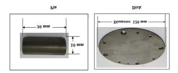
Pin (cemented carbide) and disc (stainless steel/mild steel) dimensions for dry wear testing.
Modelling Using Finite Element Method
In addition to the pin-on-disc experiments, a dry wear simulation of cemented carbide pins was also performed, using the finite element method with the ANSYS software, to obtain the contact stress field, which is the main function in the calculation of wear on pins and discs. In order to automatically create loads and constraints and build a finite element model, a wear law was integrated with time using the Euler method. The following discrete wear models assumed that the system parameters were constant and contributed to the depth of wear on each node for each step of the wear simulation.
The boundary conditions of the model were the setting points at one end of the pin that will not shift with the surface of the disc, as shown in Figure 2(a), and the joint rotation, with an angle of 10°, as shown in Figure 2(b). This analysis was needed to find the von Mises stress and the displacement that occurs in the pin and disc models. The properties of the materials for this simulation are shown in Table 2. The simulation was repeated using a mild steel disc.

The border state of the pin-on-disc model: (a) the fixing point at the end of the pin; (b) 10° angle joint rotation.
| Material | Characteristic | Value | |
|---|---|---|---|
| Cemented Carbide Pin | Density | 13,000 kgm3 | |
| Coefficient of thermal expansion | 6.7 × 10⁻⁶℃ −1 | ||
| Young modulus | 4.7 × 10¹¹ Pa | ||
| Poisson ratio | 0.23 | ||
| Yield strength | 1.3 × 10⁹ Pa | ||
| Ultimate tensile strength | 3.2 × 10⁹ Pa | ||
| Stainless Steel Disc | Density | 7,750 kgm3 | |
| Coefficient of thermal expansion | 1.7 × 10⁻⁵℃−1 | ||
| Young modulus | 1.93 × 10¹¹ Pa | ||
| Poisson ratio | 0.31 | ||
| Yield strength | 2.07 × 10⁸ Pa | ||
| Ultimate tensile strength | 5.86 × 10⁸ Pa | ||
| Mild Steel Disc | Density | 7,850 kgm3 | |
| Coefficient of thermal expansion | 1.2 × 10⁻⁵℃−1 | ||
| Young modulus | 2.0 × 10¹¹ Pa | ||
| Poisson ratio | 0.303 | ||
| Yield strength | 2.5 × 10⁸ Pa | ||
| Ultimate tensile strength | 4.75 × 10⁸ Pa | ||
Table 2 Dry material properties for dry wear simulation based on the literature.
Results and Discussion
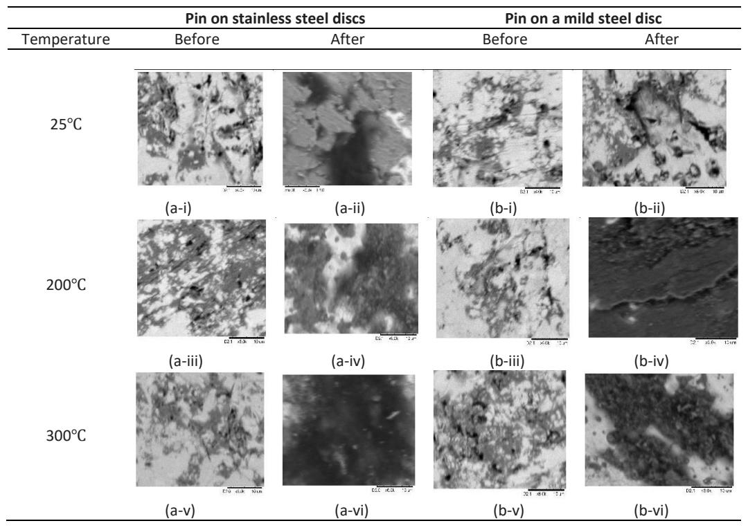
After the experiments on the cemented carbide pins were completed, the microstructure of the samples was examined using SEM, and weight loss and friction coefficients were also determined to see the changes that occurred as a result of the case of temperature and load. A micro-image of the cemented carbide pin structure on a stainless steel disc and mild steel disc is shown in Figure 3 at a load of 50 N with temperatures of 25 ℃, 200 ℃, and 300 ℃. Figure 4 shows a 100-N load-imposed pin microstructure, while Figure 5 shows the change in the microstructure of a 150-N load-imposed pin in the same temperature range. Based on Figures 3 to 5, it is clear that the higher the temperature, the more compact and close the arrangement of the particles in the cemented carbide for both pins in the stainless steel and mild steel discs. This is in line with the study done by [14].
| Pin on stainless steel discs | Pin on a mild steel disc | |||||
|---|---|---|---|---|---|---|
| Temperature | Before | After | Before | After | ||
| 25℃ | ||||||
| 200℃ | (a-i) | (a-ii) | (b-i) | (b-ii) | ||
| 300℃ | (a-iii) | (a-iv) | (b-iii) | (b-iv) | ||
| (a-v) | (a-vi) | (b-v) | (b-vi) | |||
Pin on stainless steel discs Pin on a mild steel disc Temperature Before After Before After 25℃ 200℃ (a-i) (a-ii) (b-i) (b-ii) (a-iii) (a-iv) (b-iii) (b-iv) 300℃ (a-v) (a-vi) (b-v) (b-vi)
Effect of temperature on pin microstructure of cemented carbide at a load of 50 N.
Effect of temperature on pin microstructure of cemented Carbide at a load of 100 N.
Effect of temperature on pin microstructure of cemented Carbide at a load of 150 N.
The test results also showed that increasing the temperature can increase friction because shifting surfaces expand and create thinner contact areas, leading to higher contact and shear stresses. At high temperatures, surfaces can undergo heat softening and plastic deformation, which can cause increased wear. The weight loss of the pin can be measured through the weight loss value, as shown in Tables 3 to 5. Table 3 shows that because of the friction on the stainless steel discs, there was an increase in weight loss of the cemented carbide pins from 0.0015 g at a temperature of 25 ℃, to 0.022 g at a temperature of 200 ℃, and 0.043 g at a temperature of 300 ℃, with a load of 50 N. As for the friction on the mild steel discs, the weight loss of the pins ranged from 0.0004 g at 25 \(^{\circ}\)C, to 0.0211 g at 200 \(^{\circ}\)C, and 0.0333 g at 150 \(^{\circ}\)C. The highest percentage loss value was seen at 300 \(^{\circ}\)C and a load of 150 N when the cemented carbide pin was in contact with a stainless-steel disc, at 0.55%.
Table 3 Effect of temperature on weight of cemented carbide pins at a load of 50 N.
| On stainless steel disc | On a mild steel disc | |||||
|---|---|---|---|---|---|---|
| Temperature | Retore Atter ' | Loss of pin weight (g) | Before | After | Loss of pin weight (g) | |
| 25 °C | 14.1928 | 14.1913 | 0.0015 | 14.1490 | 14.1486 | 0.0004 |
| 200 °C | 14.2719 | 14.2498 | 0.0220 | 14.1582 | 14.1371 | 0.0211 |
| 300 °C | 14.2841 | 14.2411 | 0.0430 | 14.2075 | 14.1742 | 0.0333 |
Table 4 Effect of temperature on weight of cemented carbide pins at a load of 100 N.
| On stainless steel disc | On a mild steel disc | |||||
|---|---|---|---|---|---|---|
| Temperature Before After | Loss of pin weight (g) | Before | After | Loss of pin weight (g) | ||
| 25 °C | 14.2795 | 14.2703 | 0.0092 | 14.1395 | 14.1392 | 0.0003 |
| 200 °C | 14.1916 | 14.1808 | 0.0108 | 14.2692 | 14.2590 | 0.0102 |
| 300 °C | 14.3645 | 14.3365 | 0.0280 | 14.2640 | 14.2408 | 0.0232 |
Table 5 Effect of temperature on weight of cemented carbide pins at a load of 150 N.
| On stainless steel disc | On a mild steel disc | |||||
|---|---|---|---|---|---|---|
| Temperature | Before | After | Loss of pin weight (g) | Before | After | Loss of pin weight (g) |
| 25 °C | 14.2795 | 14.2703 | 0.0092 | 14.1395 | 14.1392 | 0.0003 |
| 25 °C | 14.2285 | 14.2188 | 0.0097 | 14.1955 | 14.1951 | 0.0004 |
| 200 °C | 14.3195 | 14.2775 | 0.0420 | 14.2555 | 14.2055 | 0.0500 |
| 300 °C | 14.3595 | 14.2805 | 0.0790 | 14.2888 | 14.2331 | 0.0557 |
The load applied to the pin and disc can affect the amount of friction and wear produced. An increased load will generally lead to increased friction, as increased pressure on the surface will cause the surface of the pin and disc to deform more and lead to abrasive and adhesive wear. On the other hand, a decrease in load will result in lower friction. However, it is important to note that the relationship between load and friction is not always parallel and can depend on other factors, such as surface roughness, temperature, and the properties of the materials used. In stainless steels, the dominant factors are ductility, thermal conductivity, and strain hardening, whereas in low-to-medium carbon steels, hardness, and abrasiveness exert the primary influence.
Because these tests did not use any lubricant, the pin surfaces and discs were in direct contact with each other, which led to increased friction and higher wear compared to experiments in which lubricants were used. Therefore, load and temperature conditions should be closely monitored and controlled to ensure that the results of the pin-on-disc experiment without lubricant obtained accurately represent the real-world situation. In addition, an increase in temperature can also result in a decrease in CoF. This is because an increase in temperature causes changes in the physical and mechanical properties of the surface in contact, such as surface roughness, hardness, and adhesion. For example, higher temperatures can lead to the softening of the material and changes in the size and distribution of asperities on the surface, resulting in a decrease in CoF. According to [15], under sliding wear conditions, researchers have also attributed the reduction in wear and CoF observed at high temperatures to the formation of Fe<sub>3</sub>O<sub>4</sub>, which is thought to adhere more strongly to the surface and act better as a solid lubricant. [16] reported the formation of a 'glaze' in the worn contact. This is often described as a smoothly burnished layer forming on top of a compacted oxide layer. Similar behavior has been widely reported in the literature relating to sliding wear at high temperatures.
Figure 6 shows the CoF graph against time for the stainless steel and mild steel discs. The load imposed at room temperature was 150 N, the velocity 230 rpm, the distance 30 mm in diameter, the time 1,800 seconds. Based on Figure 6, it was found that the CoF of both cemented carbide pins increased dramatically at the beginning of the experiment until it reached its maximum value. After that, the CoF value decreased before it became constant until the end of the experiment. It was found that the CoF for cemented carbide pins was higher, in the range of 0.5 to 0.6, while for the stainless steel disc it was in the range of 0.15 to 0.27. This is because the surface roughness and hardness of stainless steel discs is higher compared to mild steel discs.
The increase in CoF with load can be attributed to various factors, such as an increase in contact pressure between the surfaces, which leads to an increase in the adhesive force and the extent of surface deformation. In some cases, the relationship between the coefficient of friction and the load can be non-linear, that is, with an increase in CoF at low loads and reduced higher loads. This can be caused by changes in the mechanics of the relationship, such as the transition from partial to full contact or the beginning of the ploughing, which can lead to a change in the behavior of friction.
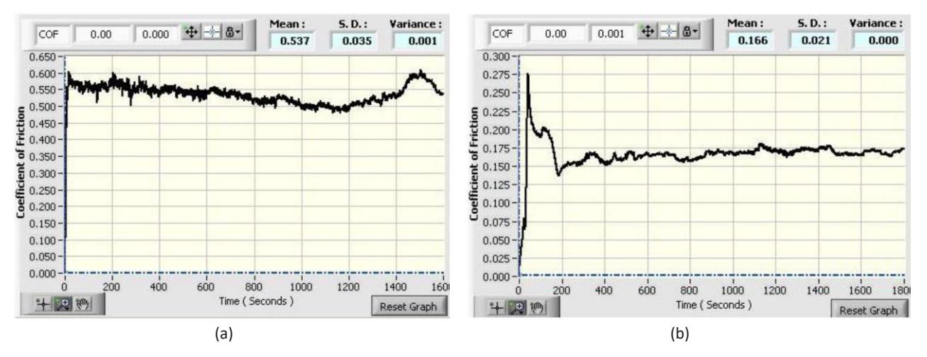
Graph of coefficient of friction (CoF) for (a) stainless steel disc, (b) mild steel disc.
A simulation of a pin-on-disc experiment was carried out. The resulting number of nodes was 1,478, while the number of elements was 221 elements. Figures 7 and 8, on the other hand, show the von Mises stress on the stainless steel disc and the mild steel disc when subjected to cemented carbide pins. Stainless steel has a lower yield strength than mild steel but higher resistance to corrosive environments. Therefore, this experiment revealed that the von Mises stress value for stainless steel was lower, at 51.759 Pa, compared to the von Mises stress of the mild steel, at 60.379 MPa. This also shows that both materials do not fail because the value of the von Mises stress was lower than the value of the yield stress, which is around 250 MPa for mild steel and 205 MPa for stainless steel, respectively. As such, it proves that mild steel discs will undergo more microstructure changes and wear out more. In addition, the deformation that occurred in the cemented carbide pins was also low, that is, between 0.969 mm and 8. 727 mm, as shown in Figure 9.
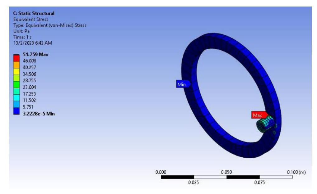
Von Mises stress between pin and stainless steel disc.
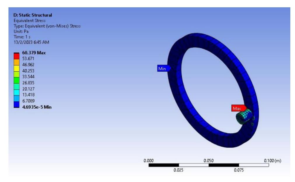
Von Mises stress between pin and mild steel disc.

Amount of deformation on the pin applied to the mild steel disc.
Conclusions
In this paper, the significant effect of load and temperature on wear behavior of cemented carbide was investigated. To improve the cutting efficiency and quality of cemented carbide and prolong the life of cutting tools, the accurate prediction of tool wear materials has become a popular topic. This study was carried out to examine the effects of temperature and load on changes in terms of microstructure, weight loss, and wear on the surface of cemented carbide pins. It was found that the wear rate for cemented carbide pins was higher when applied to stainless steel discs than on mild steel discs in a pin-on-disc experiment. The stainless steel used also had a high chromium content, thus causing it to have high rust resistance and hardness. This was evidenced by the loss of pin weight. The weight of the cemented carbide pins was found to decrease after the pins were applied to both discs. The weight loss of the cemented carbide pins was higher when a stainless steel disc was used. Increased temperature and load further increased the weight loss of the cemented carbide pins. This is because the heated pin affects the pin in terms of its mechanical properties. The results of the pin-on-disc simulation using ANSYS Mechanical showed that the value of the von Mises stress when a mild steel disc is used is higher by 60.379 Pa compared to only about 51 Pa for a stainless steel disc.
Acknowledgments
The authors gratefully thank and acknowledge the financial support of the Ministry of High Education Malaysia under the Fundamental Research Grant Scheme (FRGS/1/2022/TK09/ UKM/02/31) and Universiti Kebangsaan Malaysia. The author would also like to thank Murshidul Arif Hanafiah for his assistance in data management.
Compliance with ethics guidelines
The authors declare that they have no conflict of interest or financial conflicts to disclose.
This article does not contain any studies with human or animal subjects performed by any of the authors.