
Introduction
The umbilical cable is a complex assembly comprising diverse components and materials. Typically, it includes tubes or hoses, optical fiber cables, electrical cables, inner sheaths, and fillers, all of which are intricately assembled to form the inner core of the cable. Umbilical cables provide power, communications, and fluid connections between the subject and control system (Lu et al., 2017; Chitwood et al.; 2006, Peng et al., 2021). These connections support the subject during the preparation phase, allowing for the exchange of data and supply of essential resources such as fuel and oxygen. At liftoff, these umbilical cords are detached to allow the subject to move independently (NASA, 2002).
In spaceflight applications, before liftoff, the umbilical cables establish an important link between a space vehicle and the ground support equipment on the launch pad. These cables facilitate the transmission of communications, electrical power, and telemetry, while pipes or hoses convey essential substances such as cryogenic fluids, liquid propellants, and pressurizing and purging gases. Moreover, in the early days of space exploration, space suits were linked to spacecraft through umbilical cables to supply oxygen and enable communication during space journeys. Nevertheless, this approach was eventually superseded by the adoption of backpacks, which incorporated self-contained oxygen systems, electric batteries, and radio communication capabilities.
For subsea applications, umbilical cables are positioned on the ocean floor to provide essential control functions, energy in the form of electricity and hydraulics, as well as chemicals to subsea oil and gas wells, manifolds, and other remote-control systems, including remotely operated vehicles. The application of these umbilical cables can also be found in offshore drilling and workover operations (Yan et al., 2022). The diver's umbilical cables comprise a set of components that deliver breathing gas and various services from the surface control unit to the diver. As an integral part of the life support system, the umbilical cables undergo pre-use inspection as well as scheduled maintenance and testing. The components of the umbilical cables link to specific connectors on the diver's equipment, typically located on the helmet or full-face mask (Technical Manual U.S. Navy, 2005, Divex Diver Umbilicals, 2020). In addition, most remotely operated vehicles (ROVs) (Peter et al., 2018) establish a connection with the host ship through a neutrally buoyant tether or employ an umbilical cable designed for load-carrying, along with a tether management system (TMS) (Abel, 1994; Minor & Hirschi, 2007). The TMS can take the form of a garage-like apparatus that encases the ROV during its descent through the splash zone, or in the case of larger work-class ROVs, it may be a distinct assembly positioned atop the ROV. The function of the TMS is to adjust the length of the tether, thereby minimizing the impact of cable drag in the presence of underwater currents. The umbilical
cable, designed as an armored structure, encompasses a set of electrical conductors and fiber optics. These components play a role in the transmission of electric power, video, and data signals between the operator and TMS.
The launch vehicle is a powered craft designed to transport payloads, including crewed spacecraft or satellites, from the Earth's surface or lower atmosphere to outer space. In general, the launch vehicles initiate their missions from a designated launch pad (Logsdon, 2024). These vehicles receive support from a launch control center, accompanied by systems for facilitating tasks such as vehicle assembly and fueling.
Currently, the retraction of the umbilical cable is often implemented using a self-retracted male and female plug, which can be assembled or disassembled. In the ready-to-operate state of the launch vehicle, the male plug is connected to the female plug to establish electrical and communication connections between the vehicle with the power supplier and the control center. Upon launch of the vehicle, the male plug is separated from the female plug to disconnect the electrical and communication links with the ground units.
A review of the self-retracting plug mechanisms revealed that the first design appeared at the NASA Kennedy Space Center's Launch Complex (NASA, 2021). It employed a set of swing arms and additional retraction mechanisms to retract not only their umbilical cables but also walkways. While the swing arms were relatively straightforward, the secondary retraction systems consisted of a motorized setup designed to detach the connection from the launch vehicle. In addition, Alan and Gregory developed an umbilical system mechanism for the X-33 vehicle, which incorporated several unique design features to simplify horizontal operations and provide reliable disconnection during launch (Alan & Gregory, 2000). However, these systems were complex and costly.
In the second design, the umbilical cable was suspended in a tall tower (Department of Energy, 2021, Dalby, 2019). If the tower moved away from the launch vehicle, it would drag the cable along to retract with it. This cable was separated using explosive bolts, enabling gravity to bring down the tower. Despite the straightforwardness of the design, several complications still emerged. For instance, in the case of a failure in activating the explosive bolts, the tower would then drag the launch vehicle into a hazardous trajectory, causing a safety issue.
A subsequent design involved the umbilical cables being pulled back to the tower via chords attached to a motorized winch (Wang et al., 2020]. Once the launch begins, these chords retract, pulling the umbilical downward and back toward the tower. Recently, You et al. developed a propellant connector system, which was experimentally validated for reliability at the Satellite Launch Center (You et al., 2020). Han Tao and Dacheng Cong proposed a six-degrees-of-freedom hydraulic parallel mechanism to automate the propellant loading process (Tao & Cong, 2021). Hao Zhou et al. introduced an active-passive compliance strategy for plugging and unplugging electrical connectors before a launch mission (Zhou et al., 2024).
In practical use, the employment of plugs for retracting the umbilical cable from the launch vehicle is effective. However, with this approach, the male plug is attached to the body of the vehicle, leading to certain drawbacks. For instance, the male plug is assembled inside the body of the launch vehicle, occupying internal space, thus affecting the assembly and arrangement of other components. In the other method, the male plug is positioned outside the body of the launch vehicle, adversely affecting the aerodynamics of the vehicle. Additionally, the guidance tubes used in this case must be larger to prevent collision with the launch vehicle in the loading process.
For the foregoing reasons, this paper proposes a novel mechanism for retracting umbilicals in the launch vehicle loading process. This mechanism is extremely compact and only uses mechanical principles that borrow the launch motion of the vehicle to generate the umbilical cable-cutting action.
Design of the dynamic principle
Umbilical cables consist of three types: 22-AWG, 20-AWG, and 24-AWG, measuring 1.19, 1.4, and 1.09 mm in diameter, respectively. Each cable type is gathered into a group and wrapped by a metal cover. The proposed approach is designed by referring to the crankslider mechanism. Its structure is shown in Figure 1, and the integration of the proposed mechanism into the system is described in Figure 2. The launch vehicle is laid out in the cover and assembled on the guide tube. As the launch vehicle moves in a vertical direction under the action of the jet engine's thrust at the liftoff stage, it exerts a force (Fo) on the trigger, as shown in Figure 1. Through the connecting rod, the cutter moves to the left, cutting the umbilical cables.
Figure 1 Structure of the proposed mechanism.
Under a pushing force \(F_0\) from the launch vehicle to the trigger, the reaction force F will appear at the joint \(O_2\) along the connecting rod and is converted into two components, as shown in Eq.(1).
\[\vec{F} = \vec{F_x} + \vec{F_y} \tag{1}\] where \(F_x\) and \(F_y\) are force components along the horizontal and vertical axis. The magnitude of these components is defined by Eqs. (2) and (3).
\[F_r = F.\sin\phi \tag{2}\]
\[F_{v} = F.\cos\phi \tag{3}\] with \(\phi\) being an angle between the connecting rod and vertical axis, its value is selected to 32.7°.
The motion condition of the cutter is expressed as in Eq.(4).
\[F_X > 1.5.F_{ms} \tag{4}\] where \(F_{ms}\) is the friction force generated in the sliding groove and defined by Eq.(5).
\[F_{ms} = \varepsilon. F_Y + F_c \tag{5}\] where \(F_c\) is a friction force generated along the guide wall of the cutter, the value of which is very small and skipped to simplify the calculation. \(\varepsilon\) is a sliding friction factor. Its value is selected to 0.2 for a couple of contact materials, such as steel and steel.
Replacing Eq.(5) with Eq. (4), the condition of \(\phi\) is \(\phi > 17^{\circ}\) is obtained.
Figure 2 Assembly of the proposed mechanism.
Cutter pulling mechanism
Parameters of the cutter mechanism
When the launch vehicle moves forward out of the guide tube, it will push on the trigger, and the cutter cuts the umbilical cable off. The proposed mechanism working at different states is shown in Figure 3. The red line is the umbilical cable, where the head is connected to the launch vehicle and remains fixed to the surface of the guide tube by screws, as shown in Figure 3(a). During the moving process, the pin of the launch vehicle acts on the trigger to activate the cutter, as shown in Figure 3(b). The linear spring is always in a state of tension, meaning that it always tends to pull the cutter back to the safety position to avoid interfering with the launch vehicle, as depicted in Figure 3(c).
Pose of the cutter at different states: a) initial state, b) cutting state, and c) final state.
The pose of the proposed mechanism at the cutting state is simplified by the linkage diagram shown in Figure 4. Where O is the pivot point of the trigger; G is the gravity point of the trigger; A is the center point of the joint between the trigger and connecting rod; B is the center point of the joint between the cutter and the connecting rod; and C is the fixed point of the linear spring. The geometric relationship is expressed by Eqs. (6)–(8).
\[x_A = OA * cos \phi \tag{6}\]
\[y_A = OA * sin \phi \tag{7}\]
\[x_{R} = x_{A} + \sqrt{AB^{2} - (y_{A} - y_{B})^{2}}\] (8)
Figure 4 Linkage diagram of the proposed mechanism.
Where \(x_A\), \(y_A\) are vertical and horizontal coordinates of point A; \(x_B\) is the horizontal coordinate of point B, while the vertical coordinate of point B, \(y_B\) is fixed. The length of the spring at the cutting pose is described by Eq. (9).
\[L = x_B - x_C = x_B + 70 \tag{9}\]
The momentum equilibrium equation of the trigger around the OZ axis is expressed as Eq. (10).
\[J_{OZ}\vec{\dot{\varphi}} = \overrightarrow{M_q} + \overrightarrow{M_g} + \overrightarrow{M_{ms}} \tag{10}\] where \(\overrightarrow{M_q}\) is the moment around the OZ axis exerted by force, \(\overrightarrow{F}\); \(\overrightarrow{M_g}\) is the moment around the OZ axis exerted by force, \(\overrightarrow{P}\); \(\overrightarrow{M_{ms}}\) is the moment around OZ exerted by the friction force of the joints; its value is very small and skipped to simplify the calculation. Eq. (10) is deployed as Eq. (11).
\[I_{OZ} * \ddot{\Theta} = (F * OA * sin\Phi) - (P * OG * cos\Phi)\] \[\tag{11}\]
Through experiments, this research investigates the relationship between the travel distance of the launch vehicle in the guidance tube over time, as shown in Figure 5.
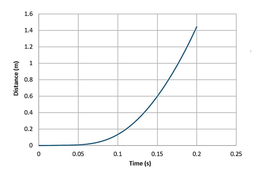
Distance–time graph of the launch vehicle.
As can be observed, after 0.2s, the vehicle reaches a travel distance of 1.4 m. Thus, the trigger is required to move into the safety position before 0.2s. To meet this requirement, the parameters of the linear spring are the main factors affecting the trigger velocity. The natural length of the spring, Lo = 40 (mm), was selected for this research, and the stiffness factor of the spring (k) was investigated from 0.5, 0.8, 1.7, 2.05, and 2.55 N/mm. Replacing these parameters in Equation (11), the relationship between the rotation angle of the trigger along with the time corresponding to each stiffness coefficient is expressed in Figure 6. As can be observed, the rotation angle of the trigger varies from 0o to about 39o during a very short time range (0–0.0014s), satisfying the requirements of the working process of the trigger (rotation movement in 0.2s). The linear spring with a stiffness coefficient of 2.5 N/mm was selected for this research as it demonstrated the best performance. This linear spring is available at Misumi Group under the model BUFSP9-1.0- [10- 550/1] (Linear spring specifications, Misumi Group, 2024).
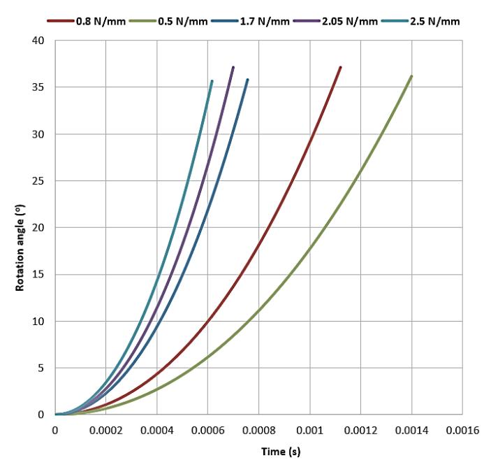
Graph showing the rotation angle of the trigger along with the time range.
Simulation of durability
Simulation plays an important role prior to fabrication, helping to optimize the design and reduce manufacturing costs (Tran et al., 2023). To simulate the cutting process, the force required to cut the umbilical cables is determined through the experiment and equals 3000N. This value is defined through the experiment and used for the input data of the simulation in Ansys software, as shown in Figure 7. The parts are made from steel SCM440, heat treated to reach 38–42 HRC hardness with a yield stress of 1200 MPa and allowable stress of 1400 MPa. The compression-only support card is set to the trigger to simulate the working process when the pin of the launch vehicle acts on the trigger, as expressed in Figure 8.
Setting up the cutting force.
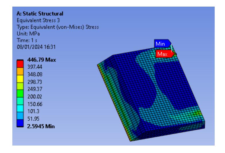
Figures 9–14 display the simulation and testing results for the strength. The stress analysis indicates that the structure provides full assurance of durability, with the highest stress measured at 792.09 Mpa, far below the yield stress of 1200 Mpa.
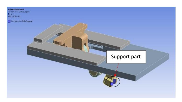
Setting up the compression-only support card to activate the trigger.
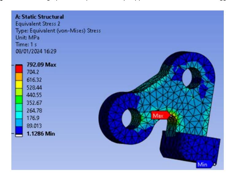
Stress result of the trigger.
Stress result of the cutter.
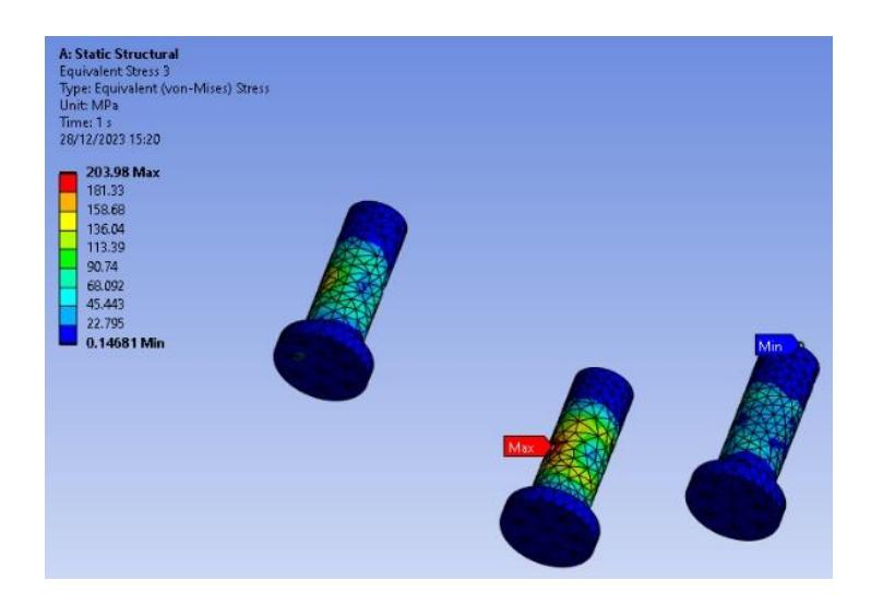
Stress result of the pivot.
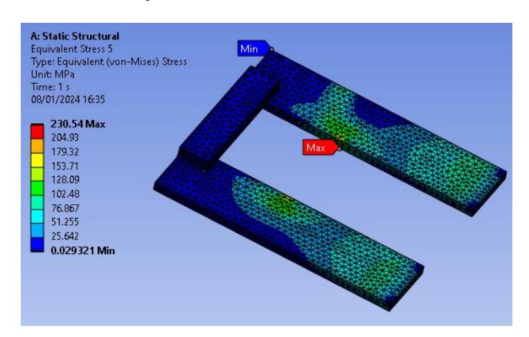
Stress result of plate 2.
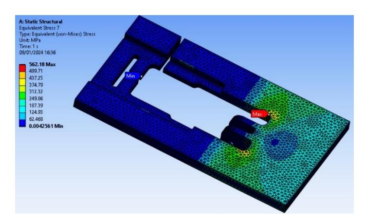
Stress result of plate 3.
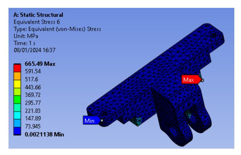
Stress result of a supporter.
Figure 15 presents the simulation and testing results for the displacement. The displacement analysis indicates a measured maximum displacement of 0.197 mm, indicating an insignificant magnitude of displacement. These results reveal that the designed structure fully satisfies the working conditions.
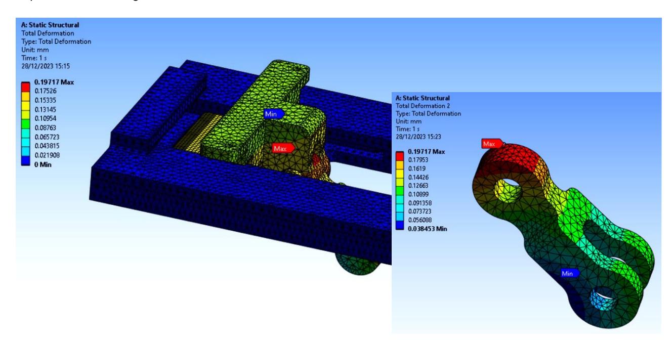
Displacement results of a connecting rod.
Results
Dynamic simulation in Adams
The working process of the proposed mechanism in Adams is simulated in this section using a multibody dynamics simulation software system developed by MSC Software Corporation. The simulation model is shown in Figure 16. As can be observed, the stiffness coefficient of the linear spring is set to 2.5 N/mm without damping using a Spring-Damper Force card.
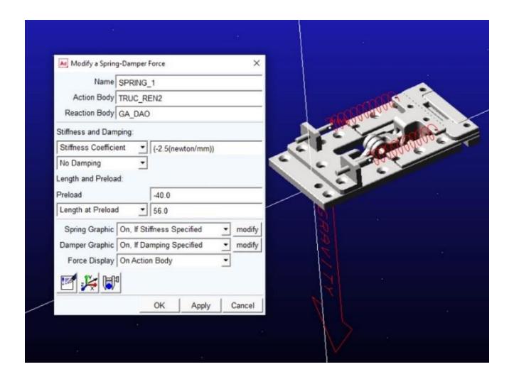
Simulation model in Adams.
Figures 17 and 18 show the simulation results where the linear spring pulls the cutter back to the right. In addition, the rotation angle of the trigger varies from 0o to 35.65o . According to the theoretical calculation in Equation (11), the trigger reaches the final position at an angle of 39.2o . The results differ in that the simulation skipped the extremely small friction force of the joints. The simulation error is only 1.15o (3.33%) and acceptable. In terms of time considerations, the trigger moves to the safety position in a short time of about 0.006s, meeting the requirement of the working process of the trigger (rotation movement in 0.2s).
Cutter position at the final state.
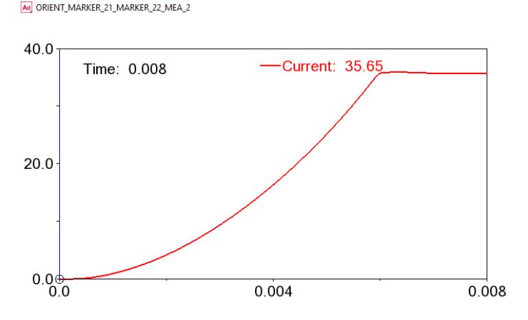
Rotation angle of the trigger.
Experimental results
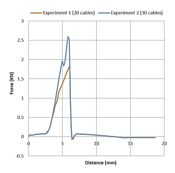
The proposed mechanism is fabricated and set up in the experiment, as shown in Figure 19. Two experiments with 20 and 31 cables were carried out in this research. Specifically, the first experiment tested the proposed mechanism with 20 cables: 8 of 22-AWG, 6 of 20-AWG, and 6 of 24-AWG, while the second experiment used 13 of 22-AWG, 10 of 20-AWG, and 8 of 24-AWG. The velocity of the launch vehicle should be 500 mm/mins.
Figure 20 presents a graph of the force acting on the trigger of the proposed mechanism. The maximum force acting on the trigger in experiments 1 and 2 was 1.82kN and 2.85kN at a distance of 6 mm, respectively. The cutting process is described in Figure 21. Pose 1 corresponds to the initial state, pose 2 is the cutting state, and pose 3 is the safety position of the trigger, where the umbilical cable is completely cut off.
Experimental setup.
Acting force on the trigger.
Pose 1 Pose 2 Pose 3
Cutting process.
Discussion
The variation in force suggests differences in experimental conditions due to a rise in the number of cables. The higher force in the second experiment indicates an increased mechanical resistance. The cutting sequence is represented by three distinct poses:
- 1. Pose 1—Initial State: The trigger mechanism is in the default position in preparation for engaging with the umbilical cable. In this state, no significant force has been applied.
- 2. Pose 2—Cutting State: The mechanism applies force to sever the umbilical cable. The peak forces observed in Figure 20 occur during this phase, overcoming the shear strength of the cable.
3. Pose 3—Safety Position: Once the cutting process has been completed, the trigger mechanism retracts to a safety position, ensuring the umbilical cable is fully severed. This final stage prevents the trigger from colliding with the launch vehicle.
In summary, the experimental results demonstrate the significant design efficiency of the proposed method. The mechanism borrows the vehicle's launch motion to generate cable-cutting action and requires no power. After umbilical retraction, the cutter is pulled back to the safety position by the spring potential energy. In comparison with the previous research (Alan & Gregory, 2000, Wang et al., 2020, You et al., 2020, Tao & Cong, 2021, Zhou et al., 2024), the proposed mechanism is effective, compact, space-saving, and energy-saving.
Conclusion
This paper introduces a novel design of an umbilical retraction device aimed at separating the electrical connection between the launch vehicle and power. The proposed mechanism takes advantage of the movement of the launch vehicle in the loading process to activate the cutting process. This means that the structure of the new mechanism is compact, with no requirement to provide energy. The simulation and experimental results confirm that the proposed mechanism works effectively with a maximum number of 20 umbilical cables, which consist of two types such as PVC and metal covers. The results have been validated in the laboratory and provide one more option for engineers seeking cable retraction devices.
Nomenclature
TMS = Tether management system ROV = Remotely operated vehicle AWG = American wire gauge HRC = Rockwell scale
Adams = Automated Dynamic Analysis of Mechanical Systems
PVC = Polyvinyl chloride
Compliance with ethics guidelines
The authors declare they have no conflict of interest or financial conflicts to disclose.
This article contains no studies with human or animal subjects performed by authors.