
Introduction
The performance capability (service life) of a cutting tool is defined as its ability to obtain cuttings that comply with established, mandatory regulatory and technical documents. Cutting tools lose their performance during the mechanical processing of metals due to wear, and the ability of the cutting tool to withstand wear is called 'cutting tool wear resistance'. Cutting tool wear directly affects the surface integrity of machined parts, including deterioration, loss of necessary cutter dimensions, increased cutting forces, appearance of vibration in the technological system, and overheating of the part. Li Xun et al. (Xun et al., 2021) studied the anti-fatigue behaviour of details, noting that during machining of Ti1023, tool wear significantly affected the surface roughness of the machined part. To improve hardness and metal-cutting tool wear resistance, various methods are used to coat tool inserts (Xun et al., 2021; Dhar et al., 2001; Ushakova et al., 2012; Migranov, 2007). Pham Minh Duc et al. (Duc et al., 2020) studied the impact of the geometrical angles of a cutting tool on its wear resistance, and they developed a novel geometry to increase this resistance.
Research on applying magnetic fields in the machining process has yielded varying results regarding their influence. The work of O.P. Gaponova and A.N. Troitsky (Gaparova et al., 2012) is notable in the field of magnetic field effects on the metal-cutting process. They investigated the impact of the magnetic field on thermal processing to increase the hardness of HSS cutters. The authors noted that the ability to cut high-speed steels is ensured by alloying steels with strong carbide-forming elements W, Mo, and V and non-carbide-forming Co. Russian scientist A.Y. Kozlyuk first applied magnetic pulse treatment with induction heating to enhance tool wear resistance (Kozlyuk, 2007). Using this method, the durability of cutting tools (turning), drills, and taps has increased by 15-20%. MN Levin et al. (Levin, 2003) studied the influence of pulsed magnetic fields on the crystallization and melting of organosilicon polymer materials. They found that pulsed magnetic field treatment of flexible-chain polymers affects the kinetics of crystallization of high-molecular organosiloxanes and polyethylene oxides. E.O. Umarov and F.Y. Yakubov (Umarov, 1966; Yakubov, 1966) determined that the magnetization of a metal-cutting tool does not always have the same effect on the stability of the cutter and the amount of thermoelectric driving force of the thermocouple; the effect depends on the specific cutting conditions.
Moreover, most experiments that analyzed the impact of a magnetic field on water properties in different conditions determined that the magnetic field has an indicative influence on water and its solutions (Otero et al., 2018; Cai et al., 2009; Bin et al., 2011). For example, Jiang, L., Yao, X., and colleagues (Jiang et al., 2017) investigated how a static magnetic field affects the scale inhibition properties of flowing water. In their study, they controlled the water flow speed, temperature, and magnetic effect time. The researchers discovered that the primary determinant for the formation of water clusters is the strength of the magnetic field. Furthermore, they observed that the speed, temperature, and duration of the process played significant roles in the number of hydrogen bonds and hydration ions present. Pornchai Premkaisorn and Wanpen Wasupongpun (Premkaisorn and Wasupongpun, 2020) analyzed the chemical properties of magnetized water, including melting point, hydrogen bonding, conductivity, viscosity, pH, and flow rate. According to their study, the magnetic field slightly affects the pH of water; however, this depends on the dissolution of water. They found that the melting point and hydrogen bonding of water increased while viscosity and flow rate decreased under the influence of a magnetic field. However, they conclude that the impact of magnetic fields on water properties requires clearer accountability in future research.
The review of previous research indicates that developing novel technologies for using CFs in the machining process is increasingly important for reducing wear, improving the service life of metal-cutting tools, and ensuring high precision in the production of mechanical engineering components. At the same time, developing and implementing new technologies for the employment of lubricating-cooling fluids, which increase cutting tool stability and ensure accuracy when processing machine parts, is important on a global scale. In this regard, one of the urgent tasks of modern manufacturing is to develop novel technologies for using lubricating-cooling fluids that achieve high accuracy in machine parts and increase tool wear resistance in multiple ways.
This research examines the impact of diverse external machining environments on HSS turning tool wear and heat generated during turning. Two types of water-based CFs are chosen to create a lubricating-cooling cutting environment. To improve the effect of selected CFs on the machining process, a magnetic field is applied to the CFs. Experimental studies compare tool wear and temperature in magnetically treated CF environments with dry cutting and traditional CF environments.
Materials and Methods
Magnetization of the CF during the Machining Process
The significance of using CF to establish a lubricating and cooling environment during the metal-cutting process and to enhance the durability of cutting tools cannot be underestimated. Extensive research has revealed that the lubricating and cooling criteria of magnetically treated CFs differ significantly from those of conventional CFs, with even greater disparities observed when the fluids are magnetized in flow (Umarov et al., 2021; Mardonov et al., 2023a; Mardonov et al., 2023b). Therefore, a unique lubricating-cooling environment can be generated by employing a strong magnetic field while a CF is in motion during the cutting procedure. This presents a challenge in addressing the magnetic treatment of CFs while they are being applied. To solve this problem, a method of directly magnetizing the CF while it is in motion was devised during the turning of a cylindrical part on a lathe (Figure 1).
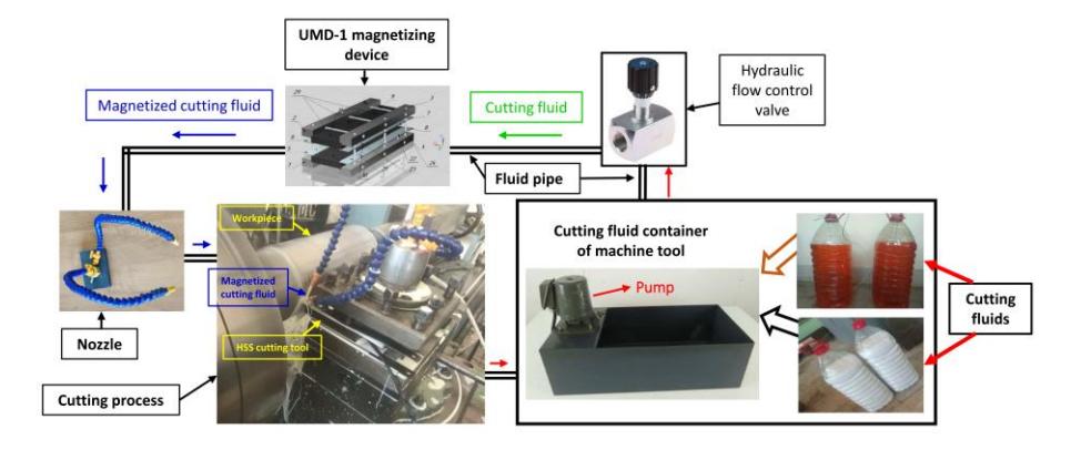
Experimental setup of using CF by magnetizing in turning.
Magnetic Treatment Setup
During machining, a fluid container in the cutting machine stores the CF. The fluid is then directed into the cutting zone via a pump and a pipe. A hydraulic flow control valve regulates the fluid flow velocity. To induce a magnetic field around the flowing CF in the pipe, it is crucial to manipulate the needed induction. This can be achieved by passing the CF through a universal magnetizing device (UMD-1), which was specially designed for this purpose. As the fluid passes through the magnetic field generated by the device, it becomes a magnetized CF at a predetermined speed (Mardonov et al., 2023b; Mardonov et al., 2023c).
The UMD-1 is a versatile device for magnetic treatment of CFs in motion, andit is highly user-friendly for applications with various metal-cutting machines, including lathes. Its primary function is to adjust the spacing of the fixed magnets and securely hold them with varying polarities, thus altering the intensity of the permanent magnetic field in the middle of them. The top magnets of the UMD-1 are spaced apart from the bottom magnets. The magnetic field induction levels can be adjusted to perform magnetic treatment of the CF, with the distance between the top and bottom magnets determining the magnetic field strength (Figure 2).
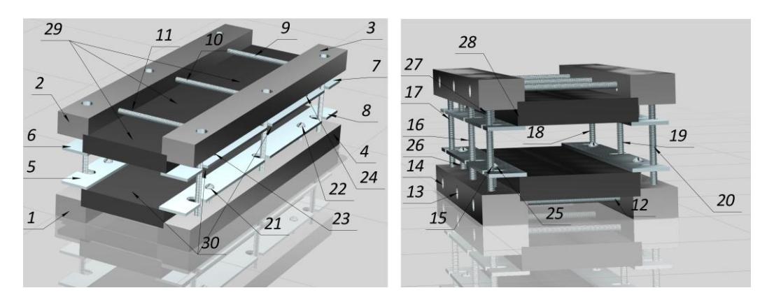
3D performance of the UMD-1: columns (1-4), clamps (5-8), bolts (9-20), screws (21-28), magnets (29, 30).
Figure 2 illustrates the placement of magnets on both the bottom and top columns, each featuring a unique pole. Afterward, hexagonal horizontal bolts are set to fit the sizes of the fixed magnets. Finally, the magnet clamps are attached with screws to hold the magnets firmly in place. The clamps and columns modify the gap between them to more easily fix the magnets. Moreover, adjusting the gap between the top and bottom columns alters the spacing between the magnets attached to each column; at the same time, it helps to alternate the magnetic field induction. The UMD-1 is a universal device because magnets of assorted sizes (length, width, height) can be placed on it. Magnets from the size of 20x10x5 (mm) to 300x80x30 mm can be fixed on the device. The space can be adjusted from 0 mm to 50 mm, depending on the dimensions of the magnets mounted on the columns. Furthermore, the UMD-1 is highly transportable and can be easily repositioned on metal-cutting machinery.
Measurement of Tool Wear
Methods for measuring cutting tool wear are divided into two types: direct measurement (cutting tool edge is measured directly) and indirect measurement (the elements of the cutting process are measured). Direct measurement methods include micrometric measurement, radioactive isotopes, electronic devices for measuring tool wear, electromechanical, and pneumatic (Simuta et al., 2010). Indirect methods allow the definition of the cutter position during the cutting process, based directly on the machining process parameters. These include cutting forces, the electromagnetic field generated during cutting, and the temperature in the cutting zone as the most suitable parameters for measuring the thermal electromotive force. Each of these methods has a specific field of application, but most require expensive, complex technical equipment. The chosen method must meet criteria such as the invariance of the measured parameter in processing modes and conditions, measurement accuracy, reliability and validity of the obtained result, and ease of technical implementation. Among these methods, the most accurate is the non-contact (indirect) measurement method, of which the Brinell magnifier is the simplest. The MPB-2 (Brinell magnifier) microscope allows measurement of linear wear down to 0.01 mm along the side of the tool. It can measure the change in size in the normal direction at the desired edge of the tool by placing it at a certain suitable distance from the end of the cutting edge. The instrument under inspection is based on a clamp mounted on the table along the support surfaces at an angle of 900.
Measurement of Cutting Temperature
To manage the cutting temperature generated in the machining zone, the natural thermocouple method is used. In the procedure, the thermo-EMF generated during the turning process is first recorded by a Hantek DSO2C10 oscilloscope. Following this, thermo-EMF indications were calibrated to temperature data. Figure 3 displays the details of the measurement setup.
Cutting temperature control setup by natural thermocouple: 1 – cutting tool, 2 – workpiece, 3 – work holder, 4 – oscillograph, 5 – workpiece rotation, 6 – brush.
Experimental Study
Cutting Fluid Preparation
Two types of lubricating and cooling fluids, water-based synthetic CFs and emulsions, are widely used in manufacturing enterprises to create a lubricating and cooling environment. The synthetic cutting fluid (SCF) is a 2% solution of K₂Cr₂O₇ (potassium dichromate) powder in water. The fluid in question is unique in that it does not cause significant metal erosion. The emulsion cutting fluid (ECF) is a 5% solution of LACTUCA LT 3000 in water and is widely used worldwide in the mechanical processing of details. Table 1 provides specifications for the sample CFs.
| Properties | Standard | Unit | Value | |
|---|---|---|---|---|
| K2Cr2O7(2% solution in water) | ||||
| Density, (T = 150C) | - | kg/m3 | 1008 | |
| Kinematic viscosity (T = 400C) | - | mm2/s | 3.7 | |
| Dynamic viscosity (T = 400C) | - | * 106 Pa*s | 427 | |
| pH (in a 2% solution) | NF T 60 193 | - | 7 | |
| TOTAL LACUCA LT 3000 | ||||
| Density, (T = 150C) | ISO 3675 | kg/m3 | 890 | |
| Kinematic viscosity (T = 400 °C) | ISO 3104 | mm2/s | 34 | |
| Dynamic viscosity (T = 300C) | - | * 106 Pa*s | 461 | |
| pH (in a 5% solution) | NF T 60 193 | - | 8.8 | |
Table 1 Properties of cutting fluid samples (ISO 6743/7).
Machining Parameters
Experiments were conducted to analyze tool flank wear and cutting temperature under four external machining environments: dry; CF1 (traditional use); CF2, which is magnetized in flowing; and CF3, which is magnetized when in the machine tool fluid reservoir (magnetized in piece). In the machining process, cylindrical blanks with a 150 mm diameter made of AISI 1045 were turned in a lathe model 1M63MF101 using an AISI M2 grade HSS solid turning tool. In addition, the tool angles were selected to have consistent specific values, and all tests were conducted using those values. To enhance the precision of the acquired outcomes, all experiments were performed in identical laboratory settings. Tables 2 and 3 give information about the tool geometry and experimental machining parameters.
Table 2 Geometric parameters of the cutting tool.
| Clearance angle – α = α1 | 6 0 -8 0 |
|---|---|
| Back rake angle - γ | 0 0 |
| Principal approach angle - φ | 450 |
| Auxiliary approach angle – φ1 | 450 |
Table 3 Machining parameters and laboratory conditions in the experimental study.
| Cutting tool material | AISI M2 |
| Workpiece material | AISI 1045 |
| Machine tool model | 1M63MF101 |
| Feed | 0.45 mm/rev |
| Cutting depth | 1 mm |
| Cutting velocity | 25, 40, 50, 60 m/min |
| Cutting time | 10 min |
| Atmosphere pressure | 755 mmHg |
| Air humidity | 16% |
| Fluid pipe diameter | 10 |
| Free magnetic treatment period | 1 hour |
Initially, the machining process was conducted under dry conditions, and the results obtained were recorded. In the next test, the workpiece was turned into the two selected CF environments. In the third test, CFs were magnetized for 60 minutes while flowing through the machine tool cooling system pipe using the universal magnetizing device UMD-1. A free magnetization time of 60 minutes of flowing CF was chosen based on previous studies (Mardonov et al., 2023a; Simuta et al., 2010). The field strength used to magnetize the flowing CFs was B=300 mT, based on previous experimental research. This shows that the field strength of B=300 mT is optimal for magnetizing water-based fluids in their flowing state. After 60 minutes of free magnetization of the CF in its flowing condition, the metal-cutting process was begun using the magnetically treated CF. While the CF was flowing into the cutting zone, the magnetization process was not stopped, i.e., the CF was repeatedly magnetized each time it passed through the magnetization device. In the fourth test, the CFs were magnetized for 24 hours under the influence of a 400 mT magnetic field by permanent magnets in the lathe container. In this case, the CFs were stationary, and after 24 hours of magnetic treatment, they were used in the cutting process.
Results
Tool Wear
As the cutting velocity increased during dry turning of the cylindrical blank, the tool flank wear also increased significantly. When the cutting velocity was set at 60 m/min, the tool flank wear reached its maximal value at VB=2.65 mm, and the cutting tool became unusable (Figure 4(a), Figure 5(a)). Then, using the same cutting modes, the same cylindrical part was machined in an SCF environment (Figure 4(b)). Using SCF at a cutting velocity of 60 m/min, the tool flank wear decreased to VB=2.4 mm compared to dry-machining conditions. In the same environment, at other cutting speeds at 25, 40, and 50 m/min, the tool flank wear was 0.45, 0.85, and 1.8 mm, respectively. Following these two experiments, the SCF was magnetized in a flowing state for 60 minutes under a permanent magnetic field strength of 300 mT, and the workpiece was machined using the magnetically treated SCF in a metal-cutting zone. Figure 4(c) shows that in all the experiments conducted at four diverse cutting velocities, the tool flank wear was significantly reduced compared to the previous two cases. At a cutting velocity of 25 m/min, VB=0.2 mm flank wear on the cutting tool resulted. When the cutting speed was set at 60 m/min, the flank wear of the cutting tool reached VB=1.1 mm. This flank wear indication was about 240% lower than the wear during dry cutting and about 218% lower than the flank wear measured in the cutting process in the traditional SCF environment. The last experiment was conducted using an SCF magnetized in the machine tool reservoir (Figure 4(d)). The result obtained was not significantly different from the traditional use of SCF; that is, the cutting tool wear resistance improved by an average of 14% compared to the traditional use of SCF. Figure 4 shows the results of the experiments conducted using different SCF environments.
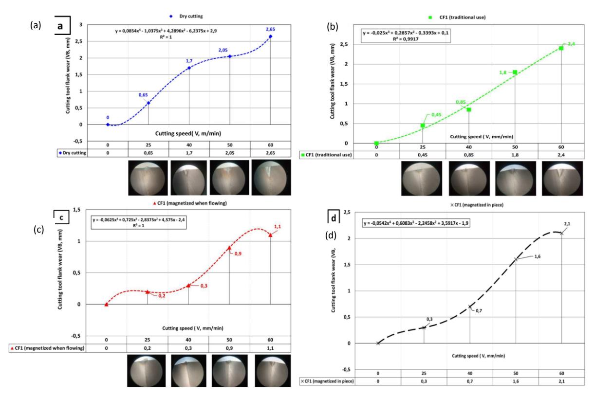
Indications of tool flank wear related to cutting speeds in four different SCF environments during turning operations.
The second experiment also showed that a magnetized CF was better than other CF environments in increasing HSS tool life. Figure 5 presents the results obtained from the experiment conducted in ECF environments.
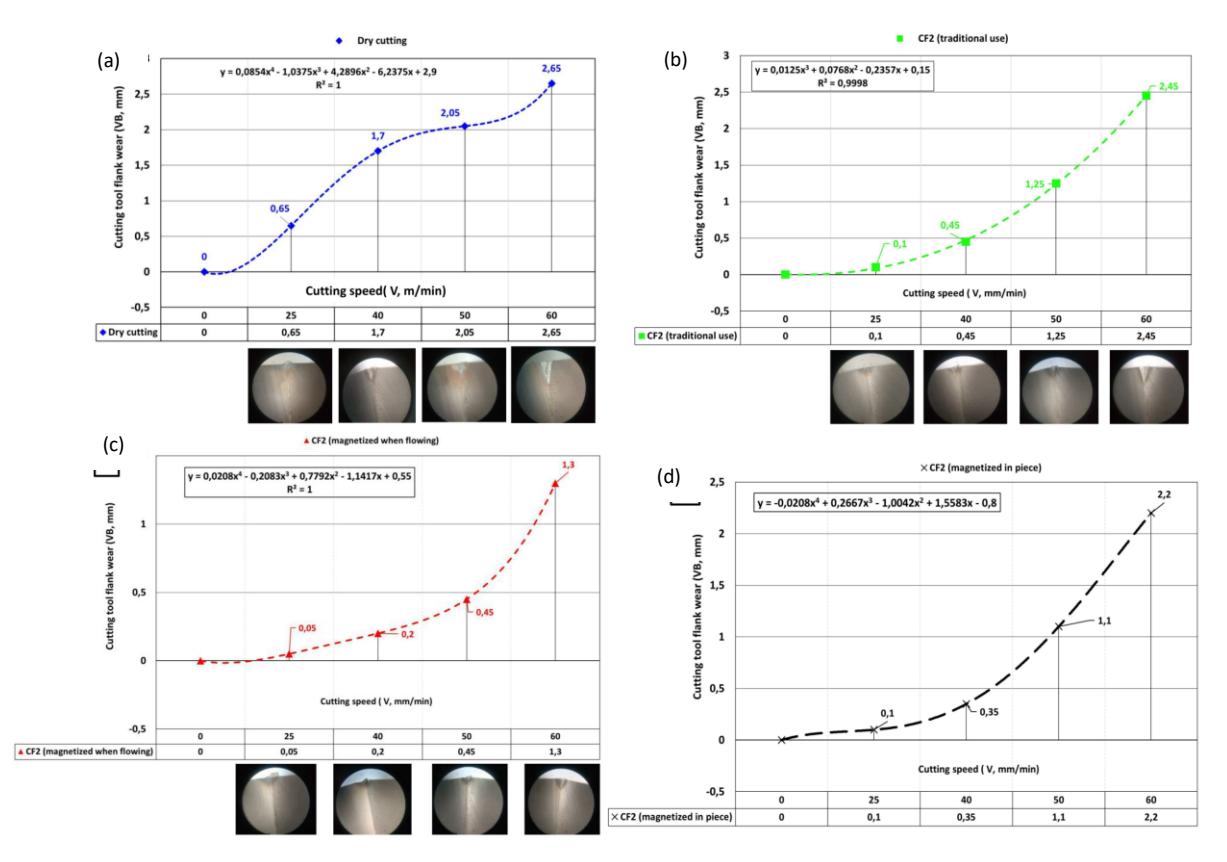
Indications of tool flank wear related to cutting speeds in four different ECF environments during turning operations.
The results show that the ECF environment in machining increased tool flank wear in relation to cutting speed and reached the highest cutting velocity of 60 m/min VB=2.45 mm (Figure 5(b)). When the ECF was treated with permanent magnets as in the third scenario, the tool flank wear decreased at VB=1.3 mm at 60 m/min (Figure 5(c)). According to the results, if a magnetized sample ECF is applied to the metal-cutting process, tool flank wear is reduced by 203% compared to the dry-machining environment (Figure 5(a)), and by 188% compared to conventional ECF use.
Cutting Temperature
The use of CFs in the machining process is known to reduce the cutting temperature. The experiments confirmed that when CFs are used in the proposed method, the cutting temperature decreases noticeably compared to when CFs are used in the traditional method.
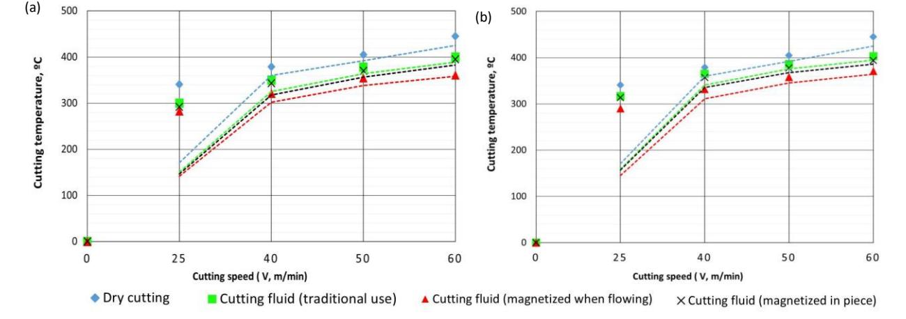
Cutting temperature in diverse machining environments. a) SCF, b) ECF.
Figure 6 shows the results of the experiments when the cutting temperature was measured. Both graphs confirm that the highest temperature during the cutting process was at Vc=60 m/min in a dry-machining environment, T=445°C. When applying a lubricating-cooling fluid medium to the process, a decrease in cutting temperature was observed. The lowest temperature at Vc=60 m/min was observed in both magnetized SCF and ECF environments, TSCF2=371°C and TECF2=3610C, respectively. When applying CF by the traditional method and when magnetizing in the reservoir, practically no change in the cutting temperature was observed. However, when applying magnetized CFs in a flowing state, the cutting temperature decreased significantly compared to other environments at all experimental cutting speeds. In the proposed method of using CFs, the cutting temperature decreased by an average of 9% in the SCF environment and by an average of 8% in the ECF environment compared to the use of CFs by the traditional method. The experimental results indicate that using CFs with magnetic treatment can reduce the temperature in the cutting zone.
Discussions
Based on the results, our initial assumptions derived from preliminary experiments and theoretical analyses have been validated. Specifically, an examination of the experiment conducted using the first CF reveals that tool flank wear increases with cutting velocity across all four test environments. Nevertheless, the corresponding tool wear curves exhibit distinct trends in each of the four environments considered, indicating the influence of varying cutting conditions. The highest flank wear on the HSS tool occurred under dry-machining conditions, with VB = 2.65 mm at a cutting speed of 60 m/min. The results also indicate that the cutting tool wear resistance improves when the workpiece is machined using a conventional lubricating-cooling environment. Under these conditions, the tool flank wear decreased to VB = 2.40 mm and VB = 2.45 mm in the two tested CFs at the highest cutting speed, respectively. The best performance was obtained when both CFs were applied under a magnetic field strength of 300 mT, where the tool flank wear values were reduced to VB = 1.10 mm and VB = 1.30 mm, respectively, at a cutting velocity of 60 m/min. A slightly better result than the traditional method of using CFs was obtained when they were used after the magnetization process in their piece condition under a field strength of 400 mT. That is, when the CFs were used after magnetic treatment in their stationary state, tool wear did not differ significantly from that indicated in the traditional use of CFs. However, when magnetically treated CFs in their flowing condition were used in the turning process, the tool flank wear decreased by 2.4 (ECF) and 2.03 (ECF) times compared to dry cutting and by 2 (SCF) and 1.88 (ECF) times in contrast to the traditional methodology of using both CFs. The improvement in the properties of magnetized CFs is responsible for this decrease in tool insert wear. Our previous studies have shown that when a magnetic field is applied to water-based liquids, their kinematic and dynamic viscosity decreases. This enhances the cooling properties of the liquids (Erkin et al., 2021). In this research, two different water-based CFs were tested, and the results demonstrated that magnetized CFs reduced the wear of the cutting tool.
In addition, the results show that the magnetization of water-based CF during the turning process decreased the temperature generated in the cutting zone. As mentioned above, this can be explained by the decrease in the viscosity of the magnetized CF. The repolarization process occurring between CF molecules flowing under the influence of a magnetic field ensures polarized movement between the liquid layers, resulting in a decrease in the total viscosity of the liquid. This is because a magnetic field acting on liquids causes the liquid molecules to align in the direction of the magnetic field flow (Boufa, 2021; Erkin et al., 2021). Such alignment of molecules due to the influence of the magnetic field leads to a decrease in the viscosity coefficient. Additionally, the reorientation of the liquid crystal lattices under the influence of magnetic field induction results in an increase in their density. Such changes in the properties of the liquid under the influence of a magnetic field also affect its thermophysical characteristics, improving thermal conductivity. This allows the magnetized CF to quickly remove the heat energy generated in the cutting zone, providing better cooling of the cutting area than conventional CFs. The reduction in cutting temperature contributes to increased stability of the cutting tool and improved surface quality of the machined part.
Conclusions
This study proposes a novel approach to increase the effectiveness of lubricating-cooling technological fluids in the metal machining process. The study suggests using CFs under the influence of a permanent magnetic field. Based on the experimental research on SCF and emulsion, the highest tool flank wear is observed during dry cutting in turning AISI 1045. A solid AISI M2 HSS tool is used in the turning passes. However, using magnetized CFs produced the most effective results. That is, using both magnetically treated samples, SCF and ECF, in turning AISI 1045 reduced the tool flank wear by 218% and 188% (V=60m/min), respectively, compared to the traditional use of both CFs. Moreover, magnetic treatment of the CFs by putting the magnets in a machine fluid container has the least influence on the tool flank wear. The results indicate that SCF and ECF, when magnetized in a machine fluid container, reduced tool flank wear by 14% and 10%, respectively, compared to their traditional use. Furthermore, magnetic treatment affects the SCF more than emulsion does. The results show that applying magnetically treated SCF reduced the tool flank wear more than magnetized emulsion. Magnetically treated CFs demonstrated superior performance in reducing machining temperature across all tested cutting speeds. Cutting temperature decreased by an average of 9% and 8%, respectively, in the magnetically treated SCF and ECF environments, compared to the traditional use of CFs.
Although numerous studies have been conducted on the application of magnetic fields in metal-cutting processes, the work done remains insufficient. In particular, researchers should consider the electromagnetic properties of the toolworkpiece-cutting fluid environment and the influence of galvanic current that may arise in this zone during the cutting process as promising areas for future research. Furthermore, future investigations should focus on studying the effects of magnetic fields on various nano-enhanced CFs.
Acknowledgement
The authors express their gratitude to the Head of the Department of Physics of Tashkent State Technical University for their close assistance in conducting the experimental experiments.
Compliance with ethics guidelines
The authors declare they have no conflict of interest or financial conflicts to disclose.
This article contains no studies with human or animal subjects performed by the authors.