
1 Introduction
Much work has been done on design of efficient coded modulation schemes for improving the performance of digital transmission systems since the publication of Ungerboeck's paper for trellis coded modulation (TCM) [1] and Imai and Hirakawa paper for block coded modulation (BCM) [1]. Recently, the increasing interest for digital mobile radio or indoor wireless systems has led to the consideration of coded modulation design for combating fading channels.
In a number of previous papers [2]-[5], codes were designed for the Rayleigh fading channel so as to maximize their diversity by not using coded modulation techniques for the Gaussian channel.
Here, an alternative approach for combating the Rayleigh fading channel is proposed. The coded modulation system is based on partitioned BCM using Reed Solomon codes which is optimum BCM for the Gaussian channel. By using different configuration of component codes which is matched with the channel characteristic, it is shown that this approach yields a better coding gain over a Gaussian and Rayleigh channel as compared to the previous approach.
There are several reasons for using Reed Solomon codes, such as:
- These codes are maximum distance separable codes, and hence, they make highly efficient use of the redundancy.
- Reed Solomon codes are burst error correcting codes, which are suitable for non-Gaussian channels.
- Reed Solomon codes provide a wide range of code rates that can be chosen such that the coded scheme has bandwidth efficiency compatible with the reference uncoded system.
For each code, we use (n, k) Reed Solomon codes over GF( 2 q ) having code symbol length 2 1 q n , minimum Hamming distance ( n k 1 ) and error correcting capability ( ) / 2 n k .
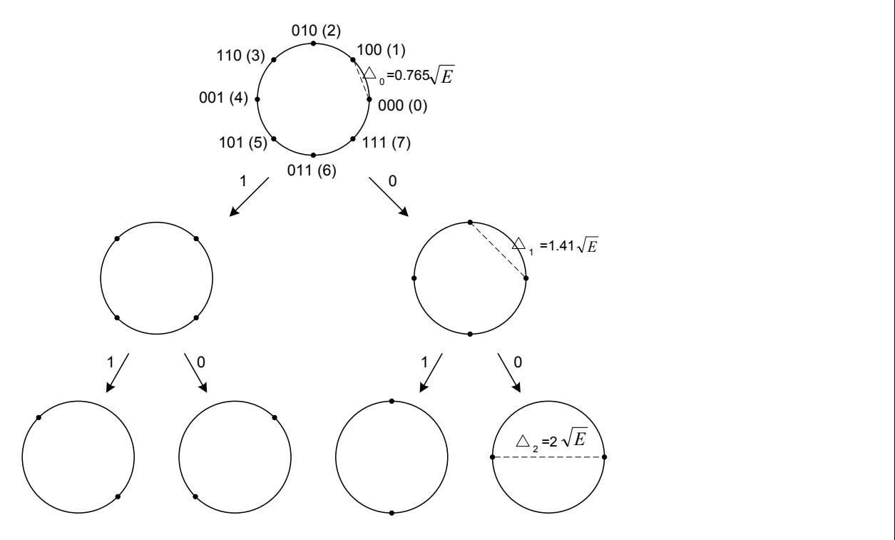
Figure 1 Set partitioned 8-PSK signal set.
In partitioned RSCM, each of the m bits defining an MPSK symbol, where 2 m M is coded and decoded by different Reed Solomon codecs. The set
partitioning principle is applied to define subsets with distances \(\Delta_i\), (i = 1 to m) that are nondecreasing with i as shown in Figure 1. Each of the m bits defines a subset and is decoded in multistage decoding schemes. This method was first proposed by Cusack [6], who used Reed Muller codes and a QAM signal set. Here, we use Reed Solomon codes combined with an MPSK signal set.
In subsection 2.1, we define a baseline coded modulation approach to which the new coded modulation system is compared. The baseline system uses a Reed Solomon code which is combined with an MPSK signal set using Gray code mapping, this approach is called non-partitioned RSCM. Specific designs of partitioned RSCM are also given in subsection 2.2. Performance analysis over the Gaussian channel and the Rayleigh fading channel are dealt with in section 3. Finally, conclusions are given in section 4.
2 Methods
2.1 Baseline Method: Non-Partitioned Reed Solomon Coded Modulation
Here, we address the issue of designing these schemes based on maximizing the time diversity (the effective length) of the code. We consider two methods generalising this approach.
2.1.1 Method 1
The first method is that a Reed Solomon code, defined over \(GF(2^{ym})\), are mapped to the signal points of a \(2^m\)-PSK signal set such that each symbol of the code consists of the concatenation of y channel symbols. In this combination the code rate is chosen such that the rate of the coded scheme is the same as the uncoded one (usually \(2^{m-1}\)-PSK). This method is based on work on [2] and [5]. The proposition in [2] and [5] indicates that the effective order of time diversity in such a mapping is at least d, the minimum Hamming distance of the Reed Solomon code.
As an example we consider a Reed Solomon (63, 42) code, defined over GF(2<sup>6</sup>), combined with 8-PSK, and hence, each code symbol consists of two concatenated 8-PSK symbols. The rate of the code is 2/3 which translates into 2 bits/s/Hz throughput, equivalent to that of uncoded OPSK.
2.1.2 Method 2
The second method is that a Reed Solomon code, defined over \(GF(2^v)\), having code rate \(R_c = m/(m+1)\) combined with a \(2^{m+1}\)-PSK signal set. In this combination the code rate is chosen such that the rate of the coded scheme is the same as the uncoded one \((2^m\)-PSK). In this case, the MPSK signal set used for modulation does not correspond to finite field over which the code is defined.
For example, a (30, 15) Reed Solomon code, defined over GF(2<sup>5</sup>), is combined with QPSK signalling. The overall coded QPSK throughput is comparable to that of uncoded BPSK, i.e., 1 bit/s/Hz.
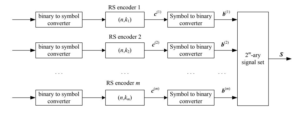
Figure 2 A Reed Solomon coded modulation based on set partitioning encoder.
2.2 Proposed Method: Partitioned Reed Solomon Coded Modulation
The block coded modulation encoder consists of m Reed Solomon codes (called Reed Solomon component codes); this is illustrated in Figure 2. The i-th block is encoded by a Reed Solomon encoder \((n, k_i)\) which generates a codeword with n symbols
\[\mathbf{c}^{(i)} = \left(c_1^{(i)}, c_2^{(i)}, \dots, c_n^{(i)}\right) \tag{1}\] where \(c_y^{(i)} \in GF(2^v)\) for \(1 \le y \le n\) and \(1 \le i \le m\). After symbol to binary converting, the outputs of m encoders can be expressed as a binary with \(v \cdot n\) columns and m rows.
\[\text{[rumus tidak dapat ditampilkan dengan baik — lihat PDF asli]}\] where \(b_q^{(i)} \in \{0,1\}\) for \(1 \le q \le v \cdot n\) and \(1 \le i \le m\). Each column of the array, \(\boldsymbol{b}_q\), will correspond to one point in the \(2^m\)-PSK signal space, \(\boldsymbol{S}\), according to Ungerboeck's set partitioning scheme [1], with the bit in the first row corresponding to the leftmost digit and the bit in the last row corresponding to the rightmost digit in the representation of the signal space points. This is illustrated in Figure 1 for the 8-PSK signal space. The array will be transmitted one column at a time, each column being represented by the corresponding signal space point.
\[\boldsymbol{b}_{a} = b_{a}^{(1)} b_{a}^{(2)} \dots b_{a}^{(m)} \tag{3}\]
Let \(s(\cdot)\) be the mapping defined on \(\boldsymbol{b}_q\) such that \(s\left(b_q^{(1)}b_q^{(2)}...b_q^{(m)}\right)\) gives a unique signal point in \(\boldsymbol{S}\).
\[S_q = s(\boldsymbol{b}_q) \tag{4}\] where \(S_a \in \{2^m - PSK \text{ signal points}\}\).
The array contains \(m \cdot n \cdot v\) bits of which \(v \cdot n \cdot m \cdot R_c\) bits are information bits. Denoting the number of information bits in ith row by \(v \cdot k_i\), we can write
\[v \cdot k_1 + v \cdot k_2 + \cdots = v \cdot m \cdot n \cdot R_c \tag{5}\]
For a given rate \(R_c\), the values of \(k_i\)'s are chosen subject to the above conditions in such a way as to maximise the minimum Euclidean distance between the codewords of the code.
2.2.1 Multistage Decoding
A multistage decoding approach has been used for partitioned RSCM. Multistage decoding of multilevel trellis modulation codes has been recently studied and analysed in a number of papers [1] and [7]. The main case of interest here is using a block encoder and block decoding algorithm for each component code of a multilevel modulation code.
The novel idea here is that in the receiver, a rotated \(2^{m+1}\)-PSK detector will be used if the transmitter uses a \(2^m\)-PSK modulator. This is illustrated in Figure 3(a), a detector of a QPSK modulator, and Figure 3(b), a detector of an 8-PSK modulator. This ensures that the received level does not fall on a decision boundary when decoding any of the bits in the symbol. It can be seen that there are two signal points of the rotated \(2^{m+1}\)-PSK signal set in each signal point's region of the \(2^m\)-PSK signal set.
For example we assume that signal \(S_0\) (label 00) of the QPSK signal set was transmitted and because of noise the detector receives a signal point of the rotated 8-PSK signal set (Figure 3(a)) which is in the decoding region of \(S_3\) (label 11), on the side close to \(S_0\). If we assume that the first bit decoding can correct the error, the receiver can estimate that \(S_0\) is the transmitted signal because it is the closest QPSK region with the decoded value of the first bit.
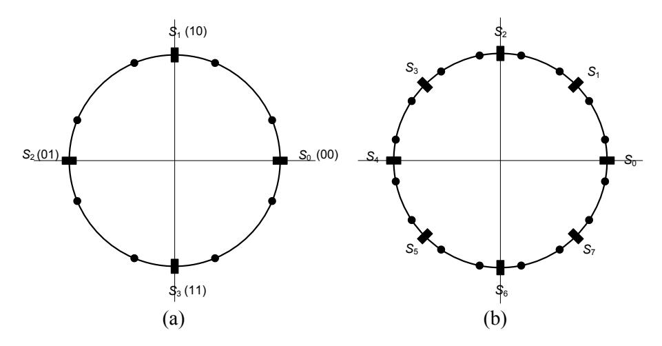
Figure 3 (a) A rotated 8-PSK signal set for a QPSK modulator. (b) A rotated 16-PSK signal set for an 8-PSK modulator
The block diagram for multistage decoding of partitioned RSCM using 8-PSK is illustrated in Figure 4. In multistage decoding of C, component codes are decoded sequentially one at a time, stage by stage. The decoded information at each stage is passed to the next stage.
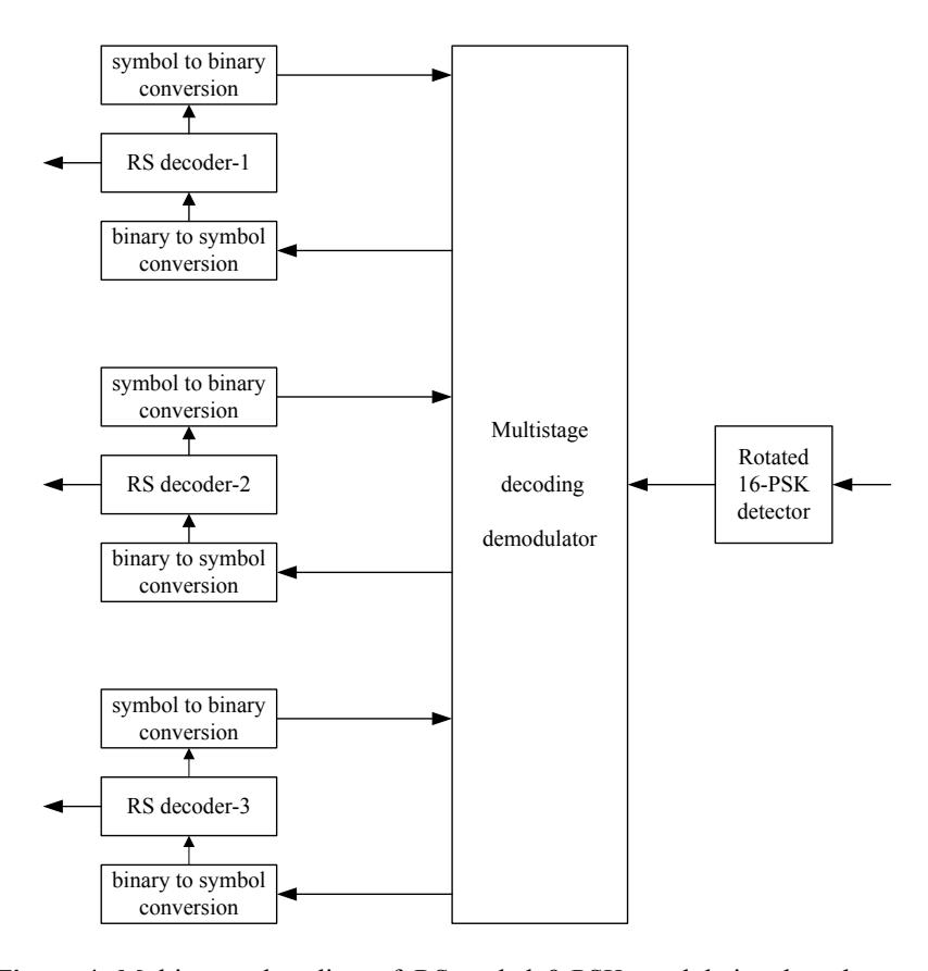
Figure 4 Multistage decoding of RS coded 8-PSK modulation based on set partitioning.
Suppose a codeword in a binary sequence, \(\boldsymbol{b} = (\boldsymbol{b}_1, \boldsymbol{b}_2, \cdots \boldsymbol{b})\) is transmitted and \(\boldsymbol{z} = (z_1, z_2, \cdots)\) is the received sequence at the demodulator, where \(z_q \in \{\text{rotated } 2^{m+1} - \text{PSK signal points}\}\).
At each stage of decoding, the following process is carrier out. Based on z, the demodulator gives a binary sequence,
\[H_i(z, b_D^{(1)} \cdots b_D^{(i-1)}, b_D^{(i+1)} \cdots b_D^{(m)})\] (6)
As discussed in the next subsection. Then the decoder performs a decoding process for \(c^{(i)} = (c_1^{(i)}, c_2^{(i)}, ..., c_n^{(i)})\), where \(1 \le i \le m\). If the decoding is successful, the decoder puts out a decoded codeword in binary sequence
\(\boldsymbol{b}_{D}^{(i)} = (b_{D1}^{(i)}b_{D2}^{(i)}\cdots)\) to the modulator. Otherwise, the decoded codeword in binary sequence is a null string with a report that an uncorrectable error has been detected (this is a decoding failure).
Either one or two iterations may be used for decoding. In the first iteration, level 1 is first decoded, then level 2 is estimated based on the result of level 1. Finally level 3 is determined based on levels 1 and 2. For the second (optional) iteration, the decoding process start from level 2 which is again decoded using the result of levels 1 and 3 from the first iteration. The corresponding is done for levels 1 and finally for level 3.
2.2.2 Hard Decision Output of the Demodulator at the i-th Stage
Suppose a signal point from a signal set S is transmitted. Let \(z_q \in \{ \text{rotated } 2^{m+1} - \text{PSK signal points} \}\), \(z_q \in z\) where \(z = (z_1, z_2, \cdots)\), be the corresponding received point at the input of demodulator. The demodulator makes a hard decision (quantization) as follows.
For the given received point \(z_q\) and decoded sublabels \(b_{Dq}^{(j)} \in \boldsymbol{b}_D^{(j)}\), where \(1 \le j < i\) and \(i < j \le m\), find the label
\[\boldsymbol{b}_{a} = b_{Da}^{(1)} \cdots \qquad \cdots \tag{7}\]
With \(b_{Dq}^{(1)}\cdots\) as a prefix and \(b_{Dq}^{(i+1)}\cdots\) as suffix such that the norm \[||z_q - s(\boldsymbol{b}_q)||\] is minimised, where \(s(\boldsymbol{b}_q)\) denotes the signal point in \(2^m\)-PSK represented by \(\boldsymbol{b}_q\). \(\boldsymbol{b}_D^{(j)}\) is a decoded codeword in a binary sequence, \(\boldsymbol{b}_D^{(i)} = \left(b_{D1}^{(i)}b_{D2}^{(i)}\cdots\right)\), as the output of the i-th stage decoder if the decoding at that stage is success, otherwise the \(\boldsymbol{b}_D^{(j)}\) is a null string. If all sub-labels, \(b_{Dq}^{(1)}\cdots\) and \(b_{Dq}^{(i+1)}\cdots\), are null, then \(\boldsymbol{b}_q\) is all signal points of \(2^m\)-PSK. The i-th sub-label, \(b_q^{(i)}\), of \(\boldsymbol{b}_q\) is the hard-decision output of the demodulator.
This process is denoted by
\[H_i(z_q, b_{Dq}^{(1)} \cdots b_{Dq}^{(i-1)}, b_{Dq}^{(i+1)} \cdots b_{Dq}^{(m)}).\] (8)
2.2.3 An Example of Multistage Decoding
Here an example of multistage decoding for Reed Solomon coded 8-PSK modulation based on set partitioning is given. The scheme consists of 3 Reed Solomon component codes. The outputs of the 3 encoders can be expressed as a binary array with \(v \cdot n\) colomns and 3 rows:
\[b_1^{(1)}\] \(b_2^{(1)}\) ...
\(b_1^{(2)}\) \(b_2^{(2)}\) ...
\(b_1^{(3)}\) \(b_2^{(3)}\) ...
We assume that the encoder gave output:
0 ··· 0 ···
Here, we consider only the first column of the array. As mentioned before, each column of the array is assigned to each point in the 8-PSK signal space according to Ungerboeck's set partitioning scheme [1]. We can see in Figure 5 that the first column of the array corresponds to \(S_0\).
Assume that at the detector, the received signal point, \(z_1\), is f in Figure 5. The modulator makes a hard decision output at the first stage as follows:
For the given received point, \(z_1\), find the label \(\boldsymbol{b}_1 = b^{(1)}b^{(2)}b^{(3)}\) such that the norm \(\|z_1 - s(\boldsymbol{b}_1)\|\) is minimised, where \(s(\boldsymbol{b}_1)\) denotes the signal point in 8-PSK represented by \(\boldsymbol{b}_1\). We find that the label \(\boldsymbol{b}_1\) which minimises the norm \(\|z_1 - s(\boldsymbol{b}_1)\|\) is 111, where s(111) is \(S_7\) in Figure 5. Therefore, the demodulator gives the first stage output \(b^{(1)} = 1\) to the first stage Reed Solomon component code decoder.
We assume that the decoding is successful and the decoder puts out a decoded codeword \(b_D^{(1)}\) with \(b_{D1}^{(1)} = 0\) to the demodulator. Using the result of the Reed Solomon decoder at the first stage, the demodulator makes a hard decision output at the second stage as follows:
For the given received point, 1 z and decoded sublabel (1) 1 0 Db , find the label (2) (3) 1 b 0b b such that the norm 1 1 z s ( ) b is minimised. The demodulator finds that the label 1 b which minimises the norm 1 1 z s ( ) b is 000, where s(000) is 0 S in Figure 5. Thus, the hard decision output of the second stage of the demodulator is (2) b 0 . The demodulator gives the second stage output (2) b 0 to the second stage Reed Solomon component code decoder.
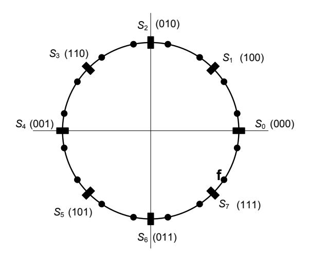
Figure 5 A rotated 16-PSK signal set for an 8-PSK modulator with binarystring label.
We also assume that the decoding is successful and the decoder puts out a decoded codeword (2) Db with (2) 1 0 Db to the demodulator. Using the result of the Reed Solomon decoder at the first and second stages, the demodulator makes a hard decision output at the third stage as follows:
For the given received point, 1 z and decoded sublabel (1) 1 0 Db and (2) 1 0 Db , find the label (3) 1 b b 00 such that the norm 1 1 z s ( ) b is minimised. The demodulator finds that the label 1 b which minimises the norm 1 1 z s ( ) b is 000, where s(000) is 0 S in Figure 5. Thus, the hard decision output of the third stage of the demodulator is (3) b 0 . The demodulator gives the third stage output (3) b 0 to the third stage Reed Solomon component code decoder.
The decoder will put out a decoded codeword \(b_D^{(3)}\) if decoding is successful to the demodulator. \(b_D^{(1)}\), \(b_D^{(2)}\) and \(b_D^{(3)}\) are decoded codewords of the first iteration multistage decoding. If the second iteration is needed, the demodulator will continue.
2.2.4 Distance Considerations
The minimum squared Euclidean distance of binary block coded 8-PSK scheme is obtained as
\[D_{\min}^2 = \min(\Delta_0^2 d_1, \Delta_1^2 d_2, \Delta_2^2 d_3)\] (9)
Thus in binary block coded scheme design, the minimum Hamming distance of each component code can be determined by set \(\Delta_0^2 d_1 \cong \Delta_1^2 d_2 \cong \Delta_2^2 d_3\).
The optimum values for minimum Hamming distance of each component code of partitioned RSCM cannot be determined. Firstly Reed Solomon codes are non-binary codes so minimum Hamming distance is not a binary measure and Equation (9) is no longer valid for this code. Secondly in multistage decoding the first stage decoding gives an output codeword to the second stage decoding, and so on. Thus the second stage decoding depends on and takes advantages from the first stage decoding, and so on. Consequently, equation (9) cannot be used to determine exactly the minimum Hamming distance of each component code.
3 Results and Discussion
In this section, the error performance of partitioned RSCM over the Gaussian channel and the Rayleigh fading channel are compared with non-partitioned RSCM and RMCM using computer simulations.
BCM using Reed Muller codes require the same approaches. At the first approach, Reed Muller code having code rate \(R_c = m/(m+1)\) combined with a \(2^{m+1}\)-PSK signal set. In this combination the code rate is chosen such that the rate of the coded scheme is the same as the uncoded one \((2^m\)-PSK). At the second approach, Reed Muller codes are used for component codes. It uses similar multistage decoding procedure for decoding the received codewords.
3.1 Code Performance over Additive Gaussian Noise Channel
Reed Solomon codes provide a wide range of code rates, thus there are many configurations of component codes for RSCM based on set partitioning. Table 1 gives a list of good codes for each specified coded symbol length for coded 8- PSK modulation and Table 2 for coded QPSK modulation.
Table 1 Configuration of good codes for Reed Solomon coded 8-PSK modulation for coded symbol length of 63 and 127.
| level | k | |
|---|---|---|
| n = 63 | n = 127 | |
| 1 | 7 | 11 |
| 2 | 59 | 119 |
| 3 | 61 | 125 |
| Throughput (bits/s/Hz) | 2.01 | 2.007 |
| Information-bit length | (7+59+61)∙6 = 762 | (11+119+125)∙7 = 1785 |
Table 2 Configuration of good codes for Reed Solomon coded QPSK modulation for coded symbol length of 31 and 63.
| level | k | |
|---|---|---|
| n = 31 | n = 63 | |
| 1 | 7 | 11 |
| 2 | 25 | 53 |
| Throughput (bits/s/Hz) | 1.03 | 1.01 |
| Information-bit length | (7+25)∙5 = 160 | (11+53)∙6 = 384 |
As previously mentioned for the binary block coded scheme, the minimum Hamming distance of each component code can be determined using equation (9). This however does not hold for multilevel codes; for example, for the best multilevel code of length 63 from Table 1
\[\Delta_0^2 d_1 = 0.586 \cdot 57 = 33.4\] \[\Delta_1^2 d_2 = 2 \cdot 5 = 10\] \[\Delta_2^2 d_3 = 4 \cdot 3 = 12\]
From the results we can see that equation (9) is not valid for the best multilevel code of each code rate and code symbol length.
Figures 6-7 show block error probability for Reed Solomon coded QPSK modulation and coded 8-PSK modulation. In these figures, the error performances are compared with those of some uncoded reference modulation systems for transmitting the same (or almost the same) number of information bits.
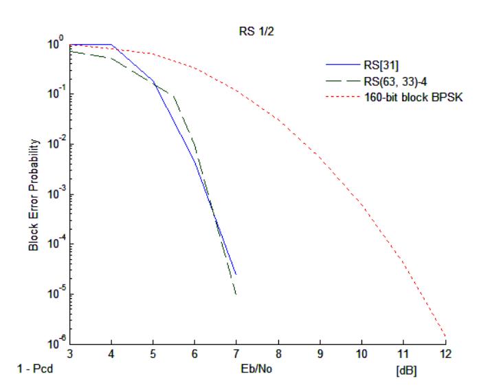
Figure 6 Error performances of coded QPSK modulation; partitioned RSCM RS[31] of length 31 listed in Table 2 and non-partitioned RS(63,33) with information-bit length of 33∙5 = 165.
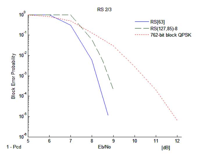
Figure 7 Error performances of coded 8-PSK; partitioned RSCM RS[63] of length 63 listed in Table 1 and non-partitioned RS(127,85) with information-bit length of 85∙7 = 595.
We can see that for coded QPSK modulation, partitioned RSCM has improvement on non-partitioned RSCM by an amount approximates equivalently to doubling code length. For coded 8-PSK modulation at block
error probability of 4 10 , set partitioning produces 1 dB more coding gain than doubling the code length.
Figure 8 shows bit error rates of various coded modulation schemes for coded QPSK modulation. Reed Muller codes used here are however more complex to decode than the Reed Solomon codes used. At bit error probability of 4 10 , partitioned RSCM has 0.75 dB more coding gain than non-partitioned RSCM with the same code length. It appears that for coded QPSK modulation, Reed Muller coded modulation based on set partitioning is worse than Reed Muller coded modulation not based on set partitioning. For example, at bit error rate 4 10 , Reed Muller coded modulation based on set partitioning, length 256, is 0.5 dB worse than Reed Muller coded modulation not based on set partitioning, length 128.
Figure 9 shows bit error rates of various coded modulation schemes of coded 8- PSK modulation. For partitioned coded modulation, it turns out that all codes have about the same performances. At a bit error rate of 4 10 - 5 10 , partitioned coded modulation has at least 1 dB coding gain over non-partitioned coded modulation for the same code length.
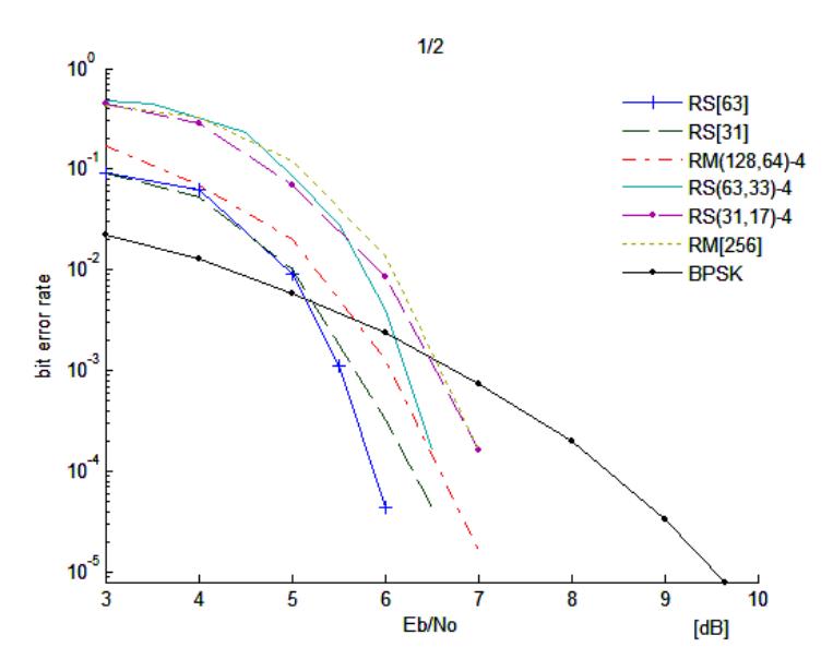
Figure 8 Error performances of coded QPSK modulation; partitioned RSCM: RS[63] of length 63 listed in Table II, RS[31] of length 31 listed in Table II, nonpartitioned: RS(63,33), RS(31,17), and partitioned RMCM RM[256] of length 256, non-partitioned 3rd-order RM(128,64).
In this channel, it appears that one iteration and two iterations multistage decoding have about the same performances.
They used binary convolutional codes for the first and second levels and a single parity check for the third level. If we use the Viterbi algorithm for decoding, the estimated information bit sequence is liable to contain error bursts. This sequence is re-encoded and fed into the decoder of the next level. Thus, the re-encoded sequence also contains error bursts. If this decoder also uses the Viterbi algorithm then it is very sensitive to these error bursts, because the algorithm is designed to deal with independent errors in the input stream.
In order to avoid this error propagation effect, they introduced interleaving between the coded bit streams of each level as explained above. The interleaving spreads the re-encoded bit streams of any two decoders for the third decoder. So it will be hardly influenced by error bursts from any of the other two decoders.
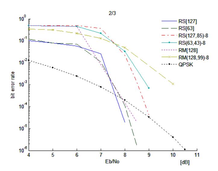
Figure 9 Error performances of coded 8-PSK modulation; partitioned RSCM: RS[127] of length 127 listed in Table I, RS[63] of length 63 listed in Table I, non-partitioned: RS(l27,85), RS(63,43), and partitioned RMCM RM[128] of length 128, non-partitioned 4th-order RM(128,99).
Reed Solomon codes have powerful error detection capabilities which are different from binary convolutional codes. In the simulations if the decoder detected the errors but it could not correct the errors, the decoder passed the input sequence to the decoder output. Therefore, the possibility of an error propagation effect because of undetected errors is very small.
3.2 Code Performance over Rayleigh Fading Channel
In this subsection, we analyse the error performance of partitioned RSCM compared with non-partitioned RSCM and RMCM over the nonselective slow Rayleigh fading channel. Here 'slow' means that the fading bandwidth is small compared to the signal bandwidth so that the receiver will be able to track the phase variations.
For all schemes of Reed Solomon coded modulation, the code symbols are interleaved before modulation in order to destroy the memory of the fading channel.
Figures 10 and 11 show bit error rates of various coded modulation schemes for coded QPSK and 8-PSK modulation. We can see that in this channel, RSCM schemes have a large coding gain to Reed Muller coded modulation schemes. We also see that the error performances of partitioned RSCM using 8-PSK are better than non-partitioned RSCM at high BER, and finally they become the same at low BER; and the error performances of partitioned RSCM using QPSK are better than those of non-partitioned RSCM. Therefore, the error performances partitioned RSCM are never worse than those of non-partitioned RSCM for the same code length.
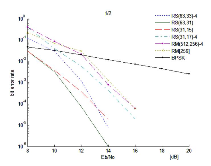
Figure 10 Error performances of coded QPSK modulation over a Rayleigh fading channel; partitioned RSCM: all RS(63,31) of length 63 whose component codes are all RS(63,31), all RS(31,15) of length 31 whose component codes are all RS(31,15), non-partitioned: RS(63,33), RS(31,17), and partitioned RMCM RM[256] of length 256, non-partitioned 4th-order RM(512, 256).
This scheme is different from the Gaussian channel in that good configurations have the same component codes. Therefore, it seems that all levels have the same distance. In other words, the fading phase is a uniformly distributed random process. By matching configuration of component codes to the channel characteristic, it is shown that partitioned RSCM can be robust codes for the Rayleigh fading channel.
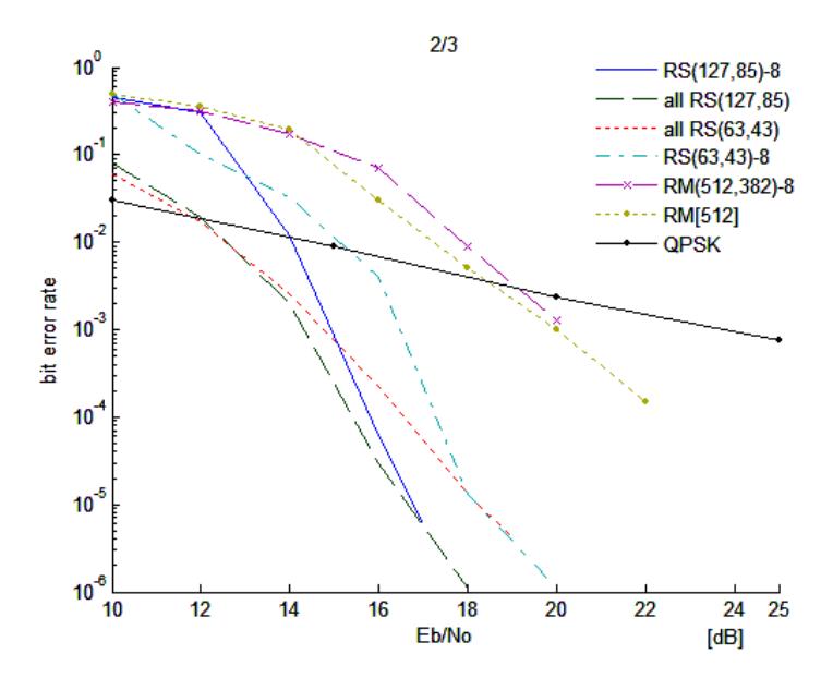
Figure 11 Error performances of coded 8-PSK modulation over a Rayleigh fading channel; partitioned RSCM: all RS(127,85) of length 127 whose component codes are all RS(127,85), all RS(63,43) of length 63 whose component codes are all RS(63,43), non-partitioned: RS(l27,85), RS(63,43), and partitioned RMCM RM[512] of length 512, non-partitioned 5th-order RM(512, 382).
The error performances of RSCM not based on set partitioning using the first approach whose code symbol consists of one channel symbol can be seen in [2]. These schemes are not simulated because they have limited configurations.
Figures 12-13 compare error performances between one iteration and two iterations multistage decoding. We can see that one and two iterations have different good codes. The good codes of one and two iterations differ by 0.5 dB at a bit error rate of 4 10 .
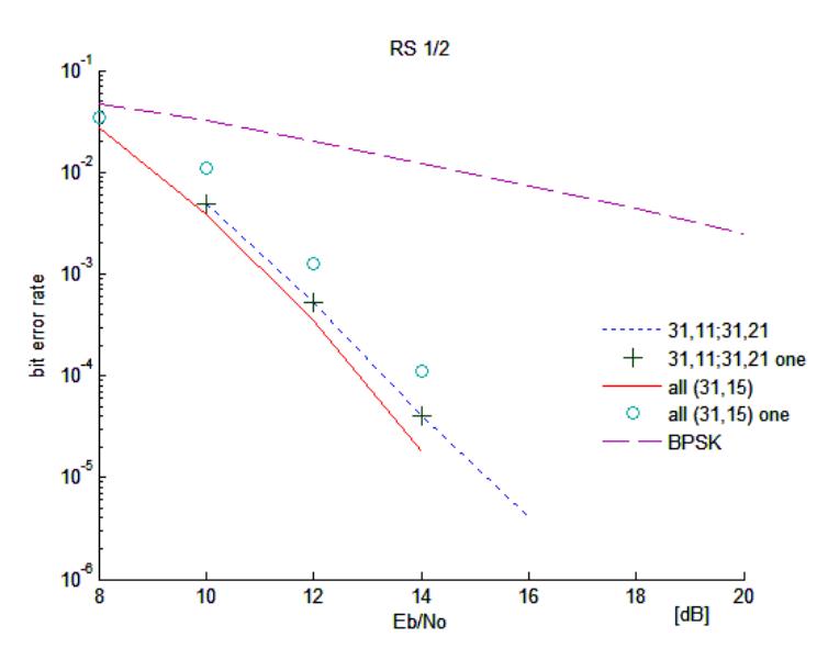
Figure 12 Error performances over a Rayleigh fading channel of RS coded QPSK modulation based on set partitioning using two iterations multistage decoding: all (31,15) of length 31 whose component codes are all RS(3l ,15), 31,11;31,21 of length 31 whose component codes are RS(31,11) and RS(31,21), and one iteration multistage decoding: all (31,15) one, 31,11;31,21 one.
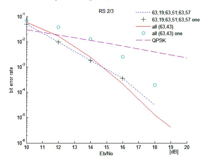
Figure 13 Error performances over a Rayleigh fading channel of RS coded 8- PSK modulation based on set partitioning using two iterations multistage decoding: all (63,43) of length 63 whose component codes are all RS(63,43), 63,19;63,51;63,57 of length 63 whose component codes are RS(63,19), RS(63,5l), and RS(63,57), and one iteration multistage decoding: all (63,43) one, 63,19;63,51;63,57 one.
In Figure 12, a good code of one iteration decoding has component codes RS(31,11) and RS(31,21), and in Figure 13 the good code has component codes RS(63,19), RS(63,51) and RS(63,57).
Therefore we can conclude that in this channel, two iteration multistage decoding must be used. This because the good codes have the same component codes, thus the first level component code also needs decoded codewords of other levels.
4 Conclusion
In this paper, construction of partitioned Reed Solomon coded modulation (RSCM) which is robust for the additive white Gaussian noise channel and a Rayleigh fading channel is proposed. By matching configuration of component codes with the channel characteristics, it is shown that this system is robust for the Gaussian and a Rayleigh fading channel.
Its error performances were compared with those of non-partitioned RSCM and coded MPSK modulation using binary codes, Reed Muller codes. It appears that partitioned RSCM performs better than non-partitioned RSCM and RMCM over the Gaussian and a Rayleigh fading channel.