
1 Introduction
Rapid development in wireless communications systems has demanded multiband or wideband antennas to support different technologies and standards. Wireless Local Area Network, now has various standards, i.e IEEE 802.11 b/g as one of WLAN standard operating at frequency ranging from 2.4 GHz to 2.48 GHz, while IEEE 802.11a/g is using frequency from 5.15 GHz to 5.35 GHz or 5.725 GHz to 5.825 GHz. Those WLAN standards are designed for short range of up to approximately one or two hundred meters from the transmitter (WiFi standard). Other standards, such as IEEE 802.16 d/e is designed to obtain wider coverage operating at other frequencies, and is known as WiMax technology. WiMax has various frequency allocations and differs from country to country. In Indonesia frequency bands of 2.3-2.4 GHz and 3.3- 3.7 GHz have been assigned to support WiMax technology. Therefore, there is a need to produce antennas that can accommodate different frequency bands to support different technologies and standards.
There are several papers on dual band or multi band antennas to comply with the 802.11 a/b/g and IEEE 802.16 d/e standards. Liu, et al. [1] proposed inverted-F antenna that can cover the 2.4/5.2 GHz WLAN bands. Raj, et al. [2] proposed coplanar antenna printed on FR4 which operates on 2.4/5.2/5.8 GHz bands. Wu, et al. [3] reported dual broadband slot antenna, in which two wide resonances were obtained by using a U-shaped strip inset at the center of the slot antenna on a substrate with relative permittivity of 4.7. Another technique to make a compact microstrip antenna can be found in [4], which also present many issues related to recent development in designing compact antenna technologies. Motivated by Chen, et.al [5]-[7] and also by [8], in this paper we propose to design and fabricate an antenna prototype that has wideband and multiband charactersitics.
The rest of the paper is organized as follows. Section 2 presents the wideband and multiband antenna design and simulation. Section 3 describes antenna fabrication and measurement. Section 4 present analysis and discussion, and finally, section 5 summarizes and concludes the entire works.
2 Antenna Design and Simulation
2.1 Wideband Design Approach
Wideband antenna in this proposed work constitutes a circular patch implemented as shown in Figure 1(a), which is then modified by creating a circular cut to produce the desired wideband characteristics as shown in Figure 1(b). The proposed antenna was designed and implemented using FR4 epoxy dielectric substrate with dielectric permittivity \(\varepsilon_r = 4.3\) and thickness h = 0.8 mm. Figure 1(a) shows the basic design of wideband antenna [9]. The antenna consist of circular patch and a CPW-fed line [10]-[11]. The CPW fed line consist of a center strip and two finite square patches of the same size that are situated symmetrically on each side of the center strip acting as groundplane. To produce a wideband characteristics between 2.3 – around 6 GHz frequency band, the circular patch has radius of Q = 16 mm or diameter D = 32 mm, a center strip width, S = 2.4 mm and a CPW gap, W = 0.2. The other dimension are P = 50.9 mm, L = 33 mm, \(G_P = 16\) mm, \(G_L = 15.1\) mm, \(H_I = 1.3\) mm, and \(H_2\)= 1.6 mm. This antena has return loss of < -10 dB form 2.1 - 5.0 GHz showing a wideband characteristic. However in our case, we need to extend the design bandwidth of up to 5.9 GHz in order to cover high band WiFi and WiMax frequencies. To achieve that, we use similar technique with [12]-[13], in that we first truncate the circular patch by decreasing the length of Q as shown in Figure 1(b). It's observed that by cutting the circular patch, the bandwidth becomes
wider, but it causes shifting the low frequency to a higher frequency limit. By properly adjusting the length of the cutting edge or decreasing the length Q, a new wideband frequency from 2.3 GHz to 6 GHz can be obtained.
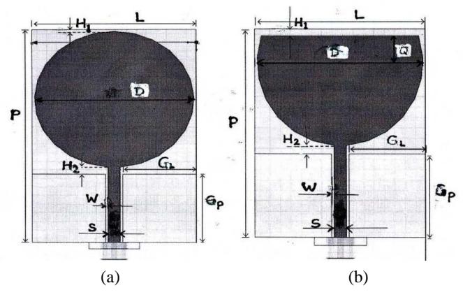
Figure 1 Wideband antenna: (a) Circular patch with 2-square ground plane, (b) Truncated patch to extend antenna bandwidth [13].
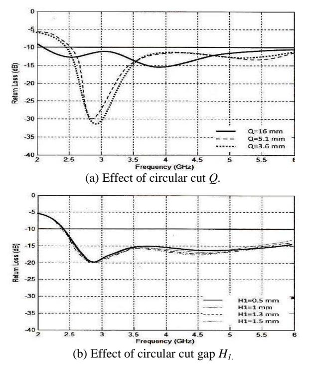
Figure 2 Return loss characteristic of truncated circular patch antenna.
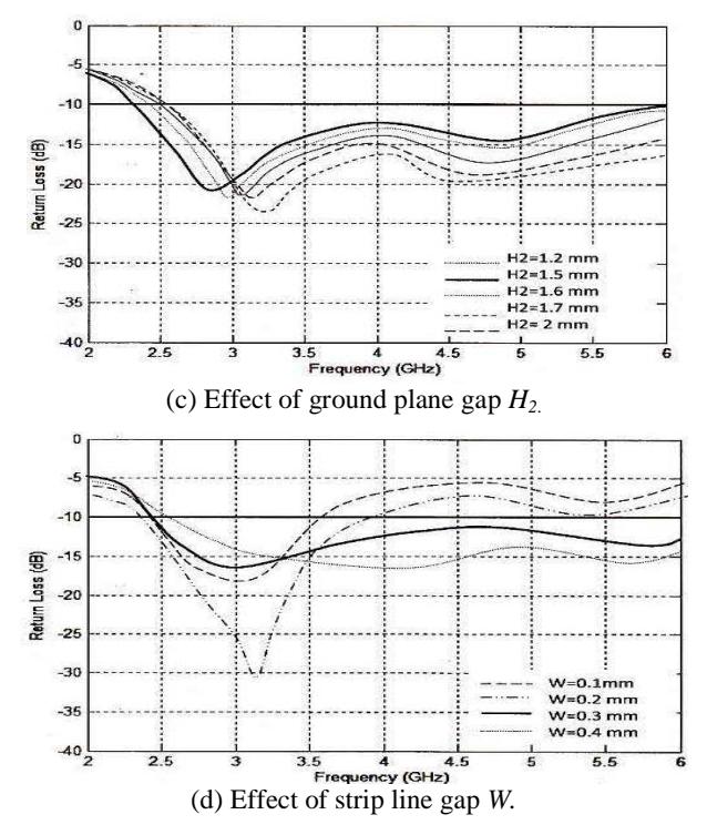
Figure 2 Continued. Return loss characteristic of truncated circular patch antenna.
Our next step is to improve impedance matching at high frequency, as we can see from Figure 2 that return loss is still critical at frequencies higher than 3.5 GHz. To do that, we then conducted parametric study by adjusting the gap width, W, and the length H1 and H2. This process shows that by decreasing W, impedance matching at frequency higher than 3.5 GHz can improve, while by increasing H2 return loss in all frequency can improves, but it is accompanied by shifting the frequency resonance to the higher frequency. In addition, increasing H1can deteriorate the return loss and also shifting the resonant frequency to the lower frequency. Optimum result to produce the desired frequency band for return loss characteristic less than 10 dB can be obtained when the dimension of Q = 5.6 mm, H1 = 0.5 mm, and H2 = 1.5 mm, W = 0.3 mm. By setting the overall dimension of P =40 mm and L = 33 mm, we obtain the dimension of D = 32 mm, GP = 16.1 mm, GL = 15 mm, and S = 2.4 mm. Fig. 2 shows simulation result from this process when we vary the length of Q, H1, H2, and W.
From Figure 2 we can see that to cover the lower band of 2.3 GHz, the dimension of Q = 16 mm shows better performance than other dimensions, the dimension of \(H_1\) is rather loose, but the dimension of \(H_2 = 1.7\) mm and W = 0.2 mm exhibit the best lower band characteristics.
2.2 Multiband Design Approach
The multiband antenna design approach was performed by imposing a pair of rectangular slot onto the circular patch in order to create stop band corresponding to the undesired frequency in the spectrum of between 2.3 to 6.0 GHz. Then otimizing the desired antenna bandwidth and center frequency was then performed by varying the dimension of rectangular slot \(L_s\) and \(P_s\) as shown in Figure 3. However, the gap of CPW fed line and the ground plane, W, the length of the circular cut, \(W_1\), and the gap between circular patch and the ground plane, \(W_2\) were affected and need to be readjusted.
Figure 3 Design of the multiband antenna.
Figure 4 (a) shows the effect of rectangular slot dimension \(P_s\) and \(L_s\), as well as the length of \(X_s\) on VSWR; while the effect of \(H_1\) and \(H_2\) are shown in Figure 4 (b) and (c) respectively.
From Figure 4 (a) we can see that the rectangular slot dimension to produce stop band characteristics around 2.8 GHz is better when \(P_s\) =17-17.2 mm, \(L_s\) = 8-10 mm, and \(X_s\) = 6 mm. Then the process is followed by readjusting the gap dimension of ground plane to obtain the desired pass bands characteristic. By keeping the dimension of W= 0.2 mm obtained from Figure 2(d), from Figure 4(b) and (c), we can see that the best obtainable pass bands that is most suitable for the desired frequency bands was found when the dimension \(H_1\) = 3.2 mm, and H2 =1.6 mm to produce tripleband characteristics, i.e. 2.3-2,8 GHz, 3.3-3.8 GHz, and the upper band above 4.6 GHz.
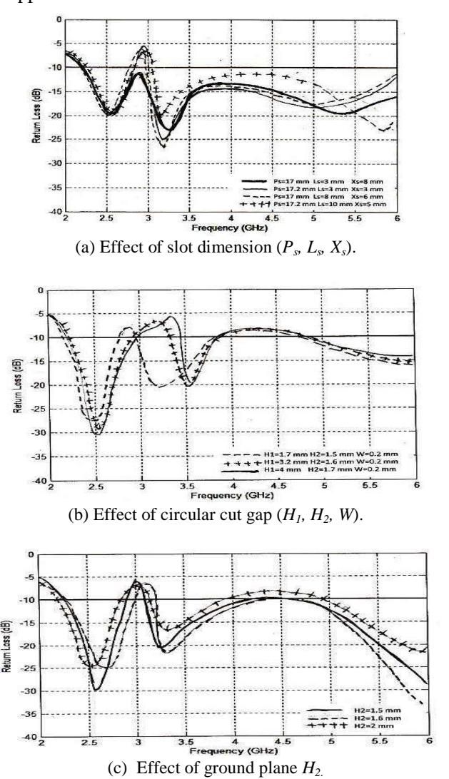
Figure 4 Simulated dimension of the multiband antenna design approach.
As we can see from Figure 4, the multiband antenna characteristics is triple band with the low band of 2.3-2.8 GHz to accomodate for WiFi/WiMax and new generation of cellular technology, the midle band of 3.3-3.7 GHz for
WiMax and extended C band applications, and above 4.6 GHz to provide for various modern wireless spectrum.
3 Antenna Fabrication and Measurement
The antenna prototypes fabricated using multiband and wideband design approach are shown in Figure 5(a) and (b), respectively. Antenna characteristics have been tested by measuring its parameters, particularly VSWR/return loss and antenna gain, to validate the simulation result as well as to verify the antenna design specification. Measurement of VSWR or return loss is most important because our proposed research is to produce wideband and multiband characteristics with sufficient impedance bandwidth requirement.
Figure 5 Antenna fabrication: (a) Wideband, (b) Multiband.
Figure 6 shows the measurement results to validate the simulation of VSWR, return loss, antenna gain, and antenna radiation pattern for wideband type of antenna.
We can see for the wideband antenna shown in Figure 6 that for VSWR = 2 (equal to return loss of - 9.54 dB), wideband characteristic can be achieved for frequency that is higher than 2.3 GHz up to 6 GHz from simulation and can go beyond 6 GHz from measurement results. At frequency between 2.5 to 3.5 GHz VSWR/return loss is better because our basic design is based on that resonant frequency [5]. Comparison of VSWR/return loss between simulation and measurement results exhibit a variation, but both results comply to the required specification. The gain measurement and simulation shows that the gain obtained from measurement shows only slightly lower than that obtained from simulation, which increases almost linearly with frequency from 0 dB at lower band of 2.3 GHz to approximately 4.5 dB at 6 GHz frequency band.
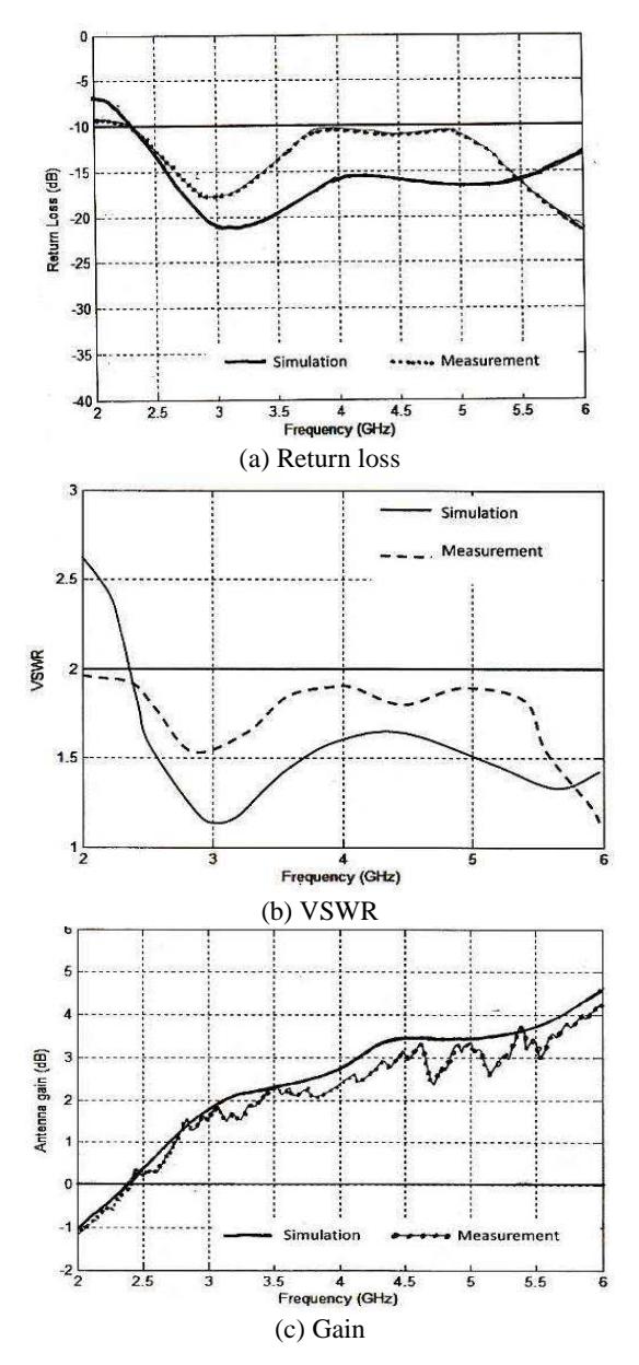
Figure 6 Wideband antenna measurement results
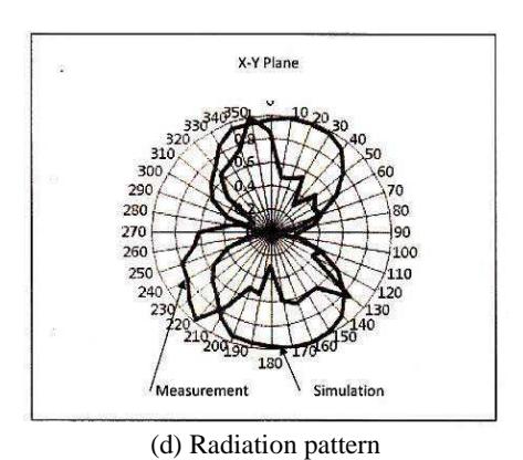
Figure 6 Continued. Wideband antenna measurement results
Figure 7 shows the measurement result to validate the simulation of VSWR, return loss, antenna gain, and antenna radiation pattern for multiband antenna.
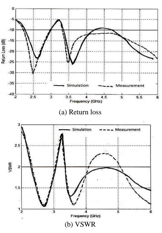
Figure 7 Multiband antenna measurement result.
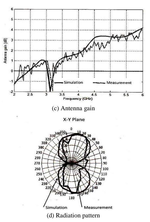
Figure 7 Continued. Multiband antenna measurement result.
Measurement results for multiband antenna shown in Figure 7 exhibit close agreements with the charactersitics obtained from simulation. We can see from Figure 7 (c) that the gain measurement varies along the frequency band, but its average shows only slightly lower than that obtained from simulation, which increases almost linearly with frequency from 0 dB at lower band of 2.3 GHz to approximately 4.5 dB at 6 GHz frequency band. However, the multiband antenna gain shows a significant drop at frequency between 2.8-3.3 GHz, which corresponds to the stop band between low and midle frequency. Therefore, the antenna gain exhibits a similar behaviour for both wideband and multiband antenna, except at the stop band. We can also see from Figure 6 (d) and 7 (d) that antenna radiation pattern shows a bidirectional horizontal (x-y plane) pattern, and exhibits near omnidirectional vertical (y-z plane) pattern, which is not shown in the picture.
4 Discussion
From extensive simulations of wideband antenna design approach, we have seen the effect of circular truncation, as well as the effect of other dimension, i.e the gap between feed line and rectangular ground plane, the gap between ground plane and circular patch, and dimension of ground plane on the antenna bandwidth. The resonant (centre) frequency seems to be rather insensitive to any changes of circular truncation (Q). This can be explained that basic design of circular patch can be retained. Circular truncation (Q) can change the behavior of higher frequency above 3.5 GHz. The gap between circular cut and the edge of the antenna (H1) is insensitive to the behavior of center frequency as well as to the antenna bandwidth characteristic of higher frequency band. However the gap between circular patch and the square ground plane (H2) is sensitive to center frequency as well as to the behavior of higher frequency bandwidth. The gap between feed line and the square ground plane patch is most sensitive to center frequency and higher frequency characteristics.
We also have seen that multiband antenna design approach can be conducted by creating a pair of simetrically rectangular slot on the circular patch to produce undesired stop band along the frequency spectrum that has been obtained in the wideband design. Once the stop band is produced, the desired center frequency and bandwidth can then be obtained by retuning the gap between circular cut and ground plane, the gap between circular cut and the antenna edge, and the gap between the fed line and the ground plane. This can be explained that multiband antenna characteristics can be created by imposing radiaton perturbation to the patch in order to produce stop bands.
5 Conclusion and Further Study
Antenna prototypes that cover all Wi-Fi,WiMAX, and other upcoming modern wireless communication system wich occupy frequency bands of between 2.3 and 6 GHz or above have been designed and implemented on FR4 substrate successfully. The antenna design has been conducted using both wideband and multiband approaches. The wideband design approach has produced an atenna characteristic that covers the frequency of 2.3 – 6 GHz. Wideband characteristic is produced by modifying a basic circular patch with square ground plane by cutting the patch and by adjusting the square ground plane to widen the bandwidth at the higher frequency band.
The multiband design approach has produced a triple band characteristics with the low band of 2.3-2.8 GHz to accomodate for WiFi/WiMax and new generation of cellular technology, the midle band of 3.3-3.7 GHz for WiMax and extended C band applications, and above 4.6 GHz to provide for various
upcoming modern wireless applications. The wideband antena gain shows increasing gain with the frequency from 0 dB at 2.3 GHz to around 4.5 dB at 6 GHz; while the multiband antenna gain shows a very similar result with that of the wideband, except for the stop band at 2.8-3.3 GHz which has a significant gain drop, corresponding to the desired stop frequency band. Antenna radiation pattern is bidirectional at x-y plane and nearly omnidirectional at y-z plane, and shows a similar patern for both wideband and multiband design approaches.
Antenna measurement results show good agrement with that obtained from simulation. Slight deviation was found in the measurement of the return loss for wideband antenna,but still meet the specification requirements. The multiband antenna requires more complex design compared to that of the wideband type. However, multiband antennas have an advantage over the wideband antenna in terms of prefiltering capability, in that any undesired frequency spectrum coming from other system or spurious emssion can be rejected at the receiving antenna front end.
In order to obtain more number of frequency bands in the multiband antenna design, our next study would focus on a more challenging design that can produce more thatn triple bands antenna, so that the antenna can provide prefiltering process for more technologies and applications with different frequency spectrum allocation.
Acknowledgements
This research is supported by the Directorate of Higher Education, Republic of Indonesia under the scheme of Decentralization Research Grant 2013, and by the Institute of Technology Bandung under the shceme of Research and Innovation Grant for Research Division. The authors thank for their financial support.