
1 Introduction
In recent times, the development of information technology and modern wireless communications has created many challenges for enhancing the performance of existing signal transmission and processing systems. It has also provided a strong motivation in the exploration of novel devices and systems particularly for supporting high rates wireless communication system that requires multiband or broadband [1]-[4]. This means that broadband devices including broadband antennas play an important role and should be forefront of research activities. Several types of broadband antennas such as bow-tie antenna, Yagi-Uda antenna, and log-periodic antenna are usually applied for the systems [5]-[8]. Recently, those antenna types have been intensively investigated to be more powerful in performance and more compact in dimension.
As is well-known, a log-periodic antenna, whose properties vary periodically with the logarithm of frequency, consists of linear dipoles as basic constituent elements. In principle it is established based on frequency independent antennas theory, where this has been studied more than 4 decades ago as the foundation of many wide bandwidth antennas [9]. The elements are usually fed from a balanced transmission line in which each element is being placed in an alternating configuration that leads to 180° phase change from the adjacent elements. This issue requires transformation unit if an unbalanced terminal need to be connected. In addition, the antenna element can be too long and therefore become impractical for lower frequency applications. Therefore, this has led many researchers to modify the original structure in order to reduce the transversal dimension. By utilizing a ground plane, dipole elements of logperiodic antenna have been modified to the monopole elements which allow half the transversal dimension [10]. Whilst, in [11], the log-periodic helical antenna has been proposed to have a smaller transversal dimension if it operates in the normal mode. Further, the implementation of fractal Koch geometry to reduce the transversal dimension elements of log-periodic antenna for UHF band applications has been reported recently [12]. However, the antenna in the later is still fed by an unbalanced transmission line which generates an impedance mismatch, thus it needs a balanced-unbalanced (balun) circuit to improve its impedance matching and feedable from a balanced transmission line.
By still applying the concept of log-periodic combined with fractal Koch geometry, in this paper, a log-periodic fractal Koch printed antenna in series iteration is proposed for numerical and experimental investigation. In contrast with [12], the proposed antenna uses the 3rd series iteration, instead of 1st and 2nd series iteration, and is equipped with a balance-unbalance (balun) circuit to improve the performance and to be available fed by a coaxial type of connector. Prior to the fabrication and experimental characterization, the proposed antenna is designed numerically on an FR-4 Epoxy dielectric substrate. The investigations of number of antenna elements as well as the effect of balun unit utilization are conducted numerically to obtain the optimum architectural design. Some basic parameters of antenna such as VSWR, impedance characteristic, gain, and radiation pattern are used as performance indicators both in the design and measurement process. In addition, the discussion related to the experimental characterization is also presented and its results are reported to be compared with the numerical ones.
2 Design Methodology
The structure of log-periodic antenna has been actually introduced more than 50 years ago [13], which is closely parallel to the concept of frequency-independent antennas. As the entire shapes of structure could not be solely specified by angles in the spherical coordinate system, hence log-periodic antennas could not be categorized as a truly frequency independent antenna. However, one element of the structures repeats itself with a logarithmic periodicity without any significant change of the performance, thus a small variation is allowed. Basically the explanation related to the design method of log-periodic antenna and its parameters has been comprehensively explained in [14]. By implementing the similarity of design process, the parameters design such as scaling factor \(\tau\), spacing factor \(\sigma\), number of antenna elements are extendable for the design of log-periodic fractal Koch printed antenna.
2.1 Antenna Design and Numerical Characterization
The proposed log periodic antenna is intended to have working bandwidth more than 1.5GHz for VSWR < 2 starting from 0.9GHz-2.4GHz to cover some wireless applications with the average gain more than 5dB. Moreover, the antenna should have compact physical dimension and be feedable using unbalanced transmission line. In the design of proposed antenna, one of the most important parameters is scaling factor \((\tau)\) which is defined as the ratio between two consecutive antenna elements in terms of length, width or distance. The relation between scaling factor \((\tau)\), length of antenna element (l), width of antenna element (d), and distance between antenna elements (s) is expressed in (1). Since each antenna element will have own resonant frequency with its bandwidth characteristic, thus the working bandwidth of antenna in overall is summation of bandwidth characteristic of each antenna element. This will establish the antenna to obtain wider working bandwidth. Hence, the numbers of antenna elements will influence the range of the working bandwidth. Another important parameter is the spacing factor \((\sigma)\) and antenna gain. The relation between parameter of \(\sigma\), \(\tau\) and antenna gain is depicted in Figure 1 [14]. It can be inferred that the antenna gain indicated by the curve lines is mostly determined by spacing factor and scaling factor. Whilst the straight line shows the optimum value of spacing factor to have the minimum scaling factor for each desired antenna gain.
\[\tau = \frac{l_n}{l_{n+1}} = \frac{d_n}{d_{n+1}} = \frac{s_n}{s_{n+1}} \tag{1}\]
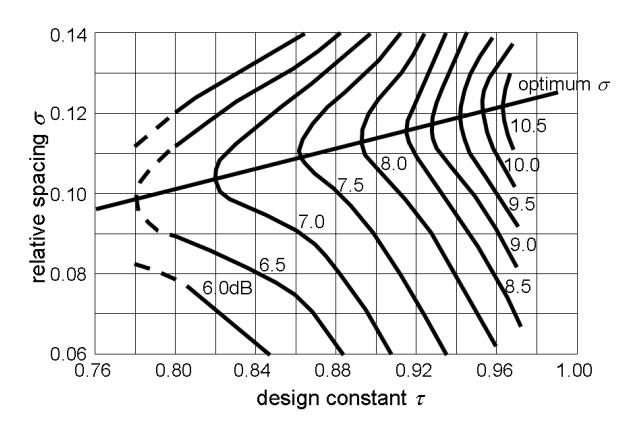
Figure 1 Relation of σ, τ and antenna gain for log-periodic antenna design.
The fractal Koch geometry is implemented by dividing a Euclidian dipole with length l element, referred as 0th iteration, to become 4 part elements, each of the part element has length of 1/4 element. The second part element is then rotated +60 degrees to horizontal; whilst the third part element is rotated -60 degrees to horizontal. The first and fourth part elements are kept parallel to horizontal. Thus, the total length will be the same as the total length of the Euclidian dipole, but the length in transversal direction from the starting point to the end point of the fractal dipole, referred as 1st iteration, will be 3/4 Euclidian dipole. Figure 2 illustrates geometry iteration of fractal Koch antenna element.
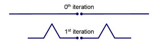
Figure 2 Geometry iteration of fractal Koch antenna element.
However, as the number of antenna elements increases, if using the 1st iteration, the total dimension of antenna in longitudinal direction becomes wider due to widening distance between antenna elements. Thus, the series iteration of fractal Koch geometry is introduced for reducing the longitudinal dimension. Figure 3 shows some series iterations of log-periodic fractal Koch antenna in which the term of 1st iteration in Figure 2 is then referred as the 1st series iteration. The series iteration is implemented by dividing a Euclidian dipole with length l element to be 7, 10, and 13 identical element parts for 2nd, 3rd, and 4th series iteration, respectively, whilst the procedure to establish the higher order series iteration is similar as applied for the 1st series iteration. Although the implementation of series iteration affects to lengthen the transversal dimension of antenna but it is not more than 10% of total dimension for the 8<sup>th</sup> series iteration.
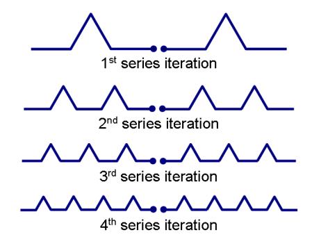
Figure 3 1st, 2nd, 3rd and 4th series iteration of fractal Koch antenna element.
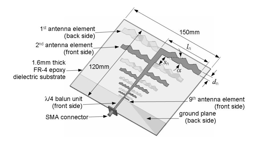
Figure 4 Design of 9 elements log-periodic fractal Koch printed antenna in 3<sup>rd</sup> series iteration equipped with balun unit.
As shown in Figure 4, the 9 elements log-periodic fractal Koch printed antenna is proposed to be designed. The \(3^{rd}\) series iteration is chosen as it is simpler than the higher number of series iterations, i.e. \(4^{th}\), \(5^{th}\), etc. In despite of the transversal dimension is 7% larger than the \(1^{st}\) series iteration, however, the longitudinal dimension can be suppressed up to 40%. The antenna which is intended to be deployed on an FR-4 Epoxy dielectric substrate with relative permittivity of 4.3, thickness of 1.6mm, and \(\tan \delta\) of 0.02 has the total dimension of 150mm x 120mm and is equipped with \(\lambda/4\) balun unit. Here, dielectric substrate and copper conductive losses of antenna elements, as well as ground plane and balun unit, are also taken into account. The working bandwidth of antenna is designed at least to be 1.6GHz range from 0.8GHz to 2.4GHz with the gain of more than 6dB.
By using equations in [14] for determining the design parameters with the scaling factor \(\tau\) of 0.098 and the spacing factor \(\sigma\) of 0.78 obtained from Figure 1, the number of antenna elements is calculated to be 9 for each side. The length of longest antenna element (\(l_{\text{max}}\)) and its width (\(d_{\text{max}}\)) can be determined from the desired lowest frequency, i.e. 0.8GHz. Hence, the maximum spacing between the longest antenna element and the next one (\(s_{\text{max}}\)) can be derived from the correlation between the length of longest antenna element (\(l_{\text{max}}\)) and its impedance characteristic. As the ratio of length or width or spacing between two consecutive antenna elements is constant and equals to the scaling factor \(\tau\); therefore the length of each element (\(l_{\text{n}}\)), the width (\(d_{\text{n}}\)), and the spacing (\(s_{\text{n}}\)) can be calculated accordingly. The calculation result of element length (\(l_{\text{n}}\)), the width (\(d_{\text{n}}\)), and the spacing (\(s_{\text{n}}\)) is summarized in Table 1.
Table 1 Dimension of each antenna element.
| \(n^{\text{th}}\) | |||
|---|---|---|---|
| n element | l (mm) | d (mm) | s (mm) |
| 1 | 89.38 | 7.50 | 15.50 |
| 2 | 69.72 | 5.85 | 12.09 |
| 3 | 54.38 | 4.56 | 9.43 |
| 4 | 42.42 | 3.56 | 7.36 |
| 5 | 33.08 | 2.78 | 5.74 |
| 6 | 25.81 | 2.17 | 4.48 |
| 7 | 20.13 | 1.69 | 3.49 |
| 8 | 15.70 | 1.32 | 2.72 |
| 9 | 12.25 | 1.03 | 2.12 |
To investigate the effect of number of antenna elements to the characteristic of antenna, the numerical investigation is conducted for antennas with 5, 7 and 9 elements, and the results in terms of working bandwidth for VSWR < 2 and impedance are depicted in Figures 5 and 6, respectively. It shows that the working bandwidth in Figure 5 is widening to higher frequency bands as the increase of number of antenna elements. This can be understood that the additional elements will add the number of antenna elements for higher frequency in which the transversal dimension is shorter than the previous consecutive element. As the additional element operates at the higher frequency and it has own bandwidth characteristic, therefore the total working bandwidth of antenna with the higher number of antenna elements increases. It should be noted the additional antenna elements are also affecting to the impedance stability of antenna as plotted in Figure 6. This is evoked by the balance contribution between the long elements impedance and the short ones. As the antenna is expected to be as compact as possible, hence there should be a tradeoff between the number of antenna elements and the physical dimension. By considering the working bandwidth response for the antenna with number of elements more than 9 which has indicated no bandwidth improvement remarkably, therefore the antenna with 9 elements is then chosen for the fabrication and characterization.
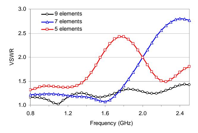
Figure 5 Working bandwidth comparison of antennas with 5, 7 and 9 elements.
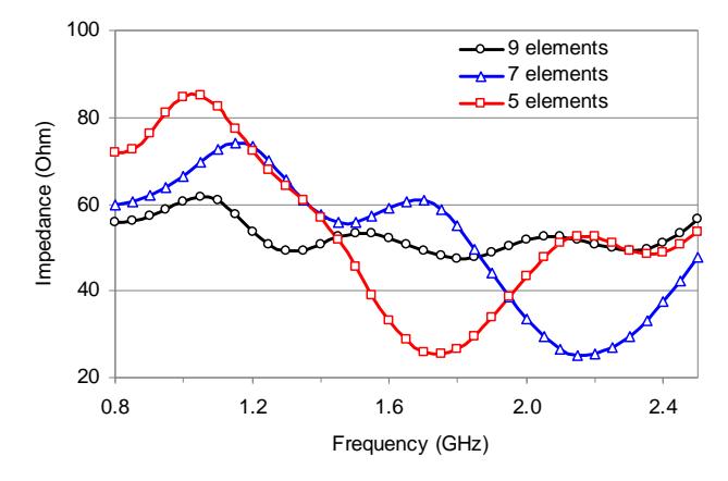
Figure 6 Impedance comparison of antennas with 5, 7 and 9 elements.
2.2 Balance-Unbalance Unit
Basically, a log-periodic antenna and its derivative are a balanced antenna type in which it is usually fed by a balanced transmission line. In order to be feedable by unbalanced transmission line such as SMA connector, a balun unit is required to transform from unbalanced to balanced circuit or vice versa. Here, a planar λ/4 microstrip line impedance matching circuit is implemented as a balun unit as shown in Figure 4. This type of balun is chosen as its construction is simple and easy to be implemented.
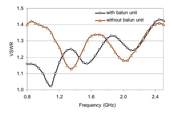
Figure 7 VSWR comparison of antenna 9 elements with and without a balun unit.
The dimension of λ/4 microstrip line can be calculated theoretically using equations in [14]. Here the width and the length of microstrip line are 2.72mm and 23.1mm, respectively. The center frequency of 1.6GHz is used to calculate the wavelength for determining the length of microstrip line. The thickness of microstrip line as well as the ground plane made from metal copper is 0.035mm. Figure 7 plots the numerical result in term of voltage standing wave ratio (VSWR) for antenna 9 elements with and without balun unit. It is seen that the use of balun unit can improve the impedance matching of antenna which is indicated by the decrease of VSWR especially in the lower frequency range, while in the higher frequency the balun unit gives no significant effect as the length of microstrip line is being mismatched. Although the balun is designed to work around center frequency of 1.6GHz, however from the simulation results its characteristic tends to have the impedance stability at frequency lower than around 1.7GHz, therefore it affects to improve VSWR of antenna at lower frequency.
3 Fabrication and Experimental Characterization
As the next step prior to the experimental characterization, the prototype of antenna based on the design result is then realized. Figure 8 shows the pictures of fabricated prototype log-periodic fractal Koch printed antenna in 3rd series iteration to be experimentally characterized. The antenna is deployed on 1.6mm thick of FR-4 Epoxy dielectric substrate through wet etching technique. The extension of center pin from SMA connector is connected to the microstrip line impedance matching circuit to feed the antenna. The measured results are plotted in Figures 9-12 for VSWR, impedance characteristic, gain, and radiation pattern respectively, with the simulated results as comparison.
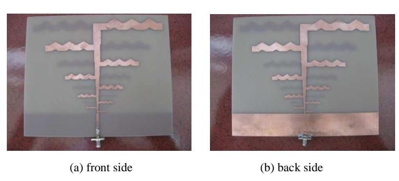
Figure 8 Pictures of fabricated prototype 9 elements log-periodic fractal Koch printed antenna in 3rd series iteration equipped with balun unit.
Although there are some discrepancies in the results, in general it should be noted that the characteristics of fabricated log-periodic fractal Koch printed antenna are agreed qualitatively with the simulated ones. In Figure 9, it shows that the fabricated antenna has working bandwidth around 1.9GHz for VSWR < 2 starting from 0.7GHz up to 2.6GHz. It is clearly seen that the measured VSWR for lower frequency, i.e. less than 1GHz, is worse than the simulated one. This is probably evoked by the dielectric substrate used in the fabrication which has value of relative permittivity slightly lower than in the design. It should be noted that the relative permittivity of FR-4 Epoxy dielectric substrate in the design is set to be 4.3 which is assumed to be flat for all frequency ranges. As the relative permittivity of dielectric substrate is lower, thus the impedance of antenna in total reacts to move to be bigger resulting the increase of VSWR and it is seen being happened at the lower frequency range. Moreover, in the real condition, the relative permittivity of dielectric substrate is usually a function of frequency and tends to be lower for higher frequency; therefore the measured working bandwidth is also affected to be narrower.
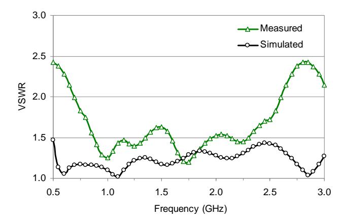
Figure 9 Measured and simulated VSWR of log-periodic fractal Koch printed antenna.
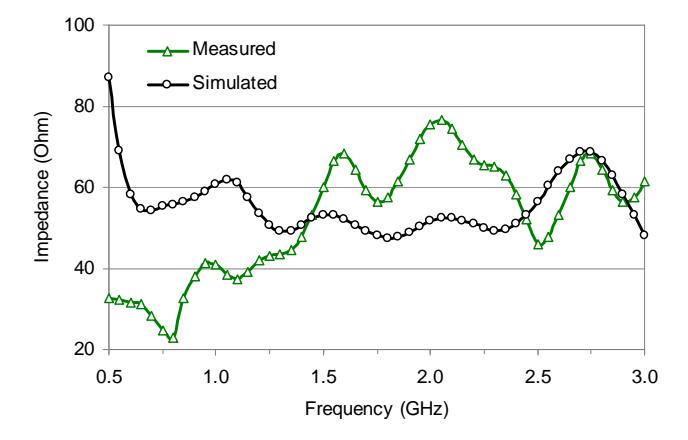
Figure 10 Measured and simulated impedance characteristic of log-periodic fractal Koch printed antenna.
Furthermore, from Figure 10 it is seen that the impedance characteristic of fabricated antenna is fluctuated between 30Ω to 75Ω for 1.5GHz to 2.5GHz frequency range. The fluctuation is possibly affected by the imperfect working of balun unit used as an impedance matching circuit. This occurs as the λ/4 microstrip line impedance matching circuit actually has a limited bandwidth response around its center frequency. The process of impedance matching between the antenna and SMA connector performs effectively along its
bandwidth response. Meanwhile, the log-periodic fractal Koch printed antenna known as a wideband antenna has characteristic impedance that depends on its antenna elements. The higher number of antenna elements affect to the larger variation of antenna impedance. Even though the use of λ/4 microstrip line impedance matching circuit is not effective for higher frequency range as shown in Figure 10, however, for other frequency range, i.e. 0.8GHz to 1.5GHz, the impedance matching circuit works well, which is indicated by the small fluctuation of impedance characteristic around 50Ω. In this frequency range, the measured result shows a better stability response than the simulated one.
In addition, the overall measured gain depicted in Figure 11 indicates that the antenna has enough gain, which is more than 6dB for frequency range above 1.6GHz. It seems that both results have similar trend for all frequency ranges with the measured result lower than the simulated one in which the gain becomes higher for the increase of frequency. It should also be noted that both results are fluctuated almost in all frequency ranges. This happens as each antenna element with its resonant frequency and bandwidth characteristic has its own gain contribution independently without any significant influences to other antenna elements.
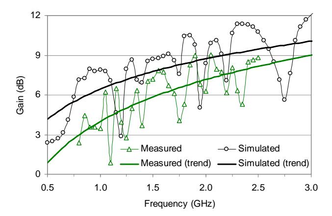
Figure 11 Measured and simulated gain of log-periodic fractal Koch printed antenna.
The similar tendency between the measured result and the simulated one is also demonstrated for the radiation patterns as plotted in Figure 12. Both results are performed at frequency of 1.6GHz for E-plane and H-plane. From the results, it shows that the beam of measured radiation pattern for E-plane is shifted less than 10o to the left side from the simulated result. Whilst for the H-plane, it is oppositely shifted to the right side about 5o from the simulated result. This discrepancy probably occurs as the misalignment of axis in measurement process, which evokes inaccuracy in obtaining the measured data. Nevertheless, as depicted in Figure 12, in general both radiation patterns coincide and agree well each other.
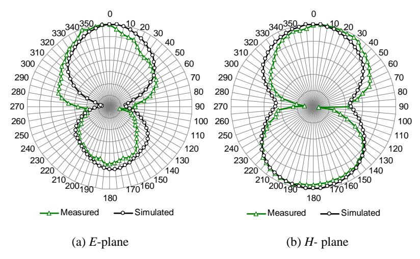
Figure 12 Measured and simulated radiation pattern of log-periodic fractal Koch printed antenna.
Conclusion
Based on the concept of log-periodic combined with fractal Koch geometry, the design and characterization of log-periodic fractal Koch printed antenna in 3rd series iteration have been investigated numerically and experimentally. The proposed antenna that has been deployed on an FR-4 Epoxy dielectric substrate with 9 antenna elements was equipped with a balun unit to be feedable from a coaxial type transmission line. It has been found the increase of number of antenna elements widened the working bandwidth in higher frequency range and improved the stability of antenna impedance. From the characterization result, it has been demonstrated that the proposed antenna with the dimension of 150mm x 120mm has the working bandwidth from 0.7GHz–2.6GHz for VSWR < 2 and the overall gain of more than 6dB for frequency range > 1.6GHz. It has been shown that the use of λ/4 microstrip line as matching impedance and balun circuits effectively enhanced the impedance matching of antenna especially in lower frequency range.
Acknowledgement
This work is partially supported by the Research Grant of Asahi Glass Foundation, Japan, 2011, and the Decentralization Research Program of Directorate General of Higher Education (DGHE), Ministry of National Education, Indonesia, 2012. The authors wish to thank team of Microwave Laboratory, Department of Electrical and Communication, Faculty of Engineering, Telkom University, Bandung, Indonesia for supporting the experimentation.