
1 0BIntroduction
The IEEE 802.15.4 low-rate wireless personal area network (LR-WPAN) medium access control standard was developed for low data rate and low power communication network applications. It supports either a non-beacon enabled or beacon enabled mode. In beacon-enabled mode, the personal area network (PAN) coordinator defines the superframe structure by regularly transmitting beacons. The superframe is divided into 16 equally sized slots and optionally can have an active and inactive portion [1].
For applications requiring a specific data bandwidth or time-critical transmission, the PAN coordinator can assign dedicated bandwidth–called a guaranteed time slot (GTS)–of the active portion to requested devices. The GTS contains one or more than one slot period and all GTSs together form the contention-free period (CFP). The main issue with the GTS mechanism is how the PAN coordinator allocates time slot duration to the devices that request a GTS. However, if the allocated devices use the GTS only partially or less than the available bandwidth, wasted bandwidth will increase, which degrades the performance of the network.
A number of mechanisms have been proposed to gain effective GTS allocation. Yu-Kai [2], Cho [3], and Shrestha [4] have determined the priorities of devices for GTS allocation. Yu-Kai, et al. [2] have studied an adaptive GTS allocation scheme (AGA) that exploits two phases in order to assign the priorities of the requested devices and schedule GTSs according to these priorities. AGA use two phases: the classification phase, i.e. determining which devices are assigned priority based on GTS usage feedback, and the GTS scheduling phase, i.e. determining which GTS resources are adequately scheduled and allocated to the device based on the priority numbers and superframe length. Simulation and numerical results showed that the latency and fairness of AGA was better than those of the IEEE 802.15.4 standard.
Cho, et al. [3] have proposed a utilization-aware dynamic GTS allocation scheme to increase utilization of the network and minimize latency. The PAN coordinator dynamically allocates GTS to its associated devices in every superframe based on their priority. Simulation results showed that the proposed scheme has better performance in terms of throughput and packet waiting time. Shrestha, et al. [4] studied an optimization-based GTS allocation scheme that was designed according to priorities of devices and the knapsack problem. The coordinator collects the bandwidth requests from the devices and then allocates GTSs to the requested devices by using the fractional knapsack problem given their priorities. Simulation results showed that the proposed scheme gained better GTS utilization and a better packet delivery ratio than those of the IEEE 802.15.4 standard.
Cheng, et al. [5] have proposed a GTS scheme that allows more devices to share the bandwidth within the same period. However, in this scheme the CFP length is always divided into 16 equally sized slots without considering the value of the superframe order (SO) and arrival data packet rate. Numerical results showed that this scheme improved bandwidth utilization. Hong et al. [6] have proposed an adaptive GTS allocation scheme to support multiple devices. The one slot duration is divided by a constant value called SlotD into smaller new slot durations based on a predefined categorization of the range of SO values, as shown in Table 1. The numerical result showed that CFP bandwidth utilization of this scheme was better than that of the IEEE 802.15.4 standard.
| Category | The value of SO | SlotD |
|---|---|---|
| Scope 1 | 0 – 2 | 1 |
| Scope 2 | 3 – 5 | 1/2 |
| Scope 3 | 6 – 8 | 1/4 |
| Scope 4 | 9 – 11 | 1/8 |
| Scope 5 | 12 – 14 | 1/16 |
Table 1 Values of SlotD in AGAS Scheme [6].
Seo [7] has proposed a dynamic CFP allocation and opportunity period for GTS allocation in a wireless body area network (WBAN) environment. Dynamic CFP allocation was added to the proposed scheme for devices to request a CFP slots to the coordinator. However, as the number of requested CFP slots increases, the length of the CFP allocation period may increase. As a consequence, the length of the contention access period (CAP) used by the devices that do not allocate GTS will decrease. Simulation results showed that the proposed protocol achieved improved throughput and latency compared with the IEEE 802.15.4 standard. Ding, et al. [8] have proposed a traffic CFP scheduling algorithm for GTS that concentrates on time-critical industrial periodic messages. Simulation results showed that the proposed GTS scheduling improved the guaranteed real-time transmission, bandwidth utilization, and energy efficiency. Chen, et al. [9-10] have proposed the Time-Sensitive Weighted Round Robin (TS-WRR) scheduler for the GTS utilization ratio in vehicular sensor networks. The numerical result using Matlab and Opnet showed that the GTS utilization of the TS-WRR algorithm was better than without time-sensitive scheduler. Shah, et al. [11] have proposed a GTS allocation strategy to reduce the underutilization of bandwidth. The proposed scheme divides the superframe duration equally into 32 slots instead of 16 slots. Thus, one GTS becomes half the time duration compared to the IEEE 802.15.4 standard. Simulation results showed that the proposed GTS strategy could improve bandwidth utilization and throughput.
In this paper, we propose the Partitioned GTS Allocation Scheme (PEGAS) for IEEE 802.15.4 networks. PEGAS aims to decide the precise moment for the starting time (GTSstart), the end (GTSend), and the length (GTSlength) of the GTS allocation for requested devices taking into account the value of the superframe order (SO), superframe duration (SD), length of data packet, and arrival data packet rate. Furthermore, PEGAS is expected to effectively allocate GTSs to the requested devices, while the length of CAP remains long enough for devices that do not receive an allocated GTS to transmit their data packets. In a previous publication, we have proposed a GTS allocation scheme and analyzed throughput, energy efficiency, and latency [12]. In this paper, we add bandwidth utilization, CAP length ratio analysis and its performance with different numbers of nodes.
2 Design of Partitioned GTS Allocation Scheme (PEGAS)
PEGAS aims to improve GTS bandwidth utilization, throughput, energy efficiency and latency by managing the GTS allocation for the requested device nodes. Different from references [5], [6], and [11], in which the CFP length is always divided into 16 equally sized slots without considering the value of the superframe order (SO) and arrival data packet rate, the one slot duration is divided by a constant value called SlotD into smaller new slot durations based on a predefined categorization of the range of SO values, while the superframe duration is divided equally into 32 slots instead of 16. PEGAS was developed taking into account the data packet length, superframe order (SO) value, and packet arrival rate to decide the length of the GTSs. According to the definition of the IEEE 802.15.4 standard, the superframe duration (SD) is as expressed in Eq. (1).
\[SD = \frac{aBaseSuperframeDuration \times 2^{SO}}{Rs}\] [in seconds] (1)
where aBaseSuperframeDuration and Rs denote the minimum duration of the superframe and the symbol data rate, which are equal to 960 symbols and 62500 symbol/second, respectively.
Let \(T_{slot}\) denote the time of one slot duration. \(T_{slot}\) is equal to \(1/16^{th}\) of SD and can be obtained by Eq. (2).
\[T_{slot} = SD / 16 \tag{2}\]
Each device with an allocated GTS ensures that the data transmission time, the acknowledgement (ACK) and interframe spacing (IFS) period can be completed before the end of its GTS period.
Let \(T_d\) be the time to transmit one data packet and receive the ACK packet. \(T_d\) can be calculated by Eq. (3).
\[T_d = \frac{L_{packet} + IFS + L_{ack}}{Rb}\][in second] (3)
where \(L_{packet}\), \(L_{ack}\), and Rb are data packet length, ACK packet length, and bit data rate, respectively. \(L_{ack}\) and Rb are equal to 88 bits and 250000 bps, respectively. The value of IFS is equal to macMinLIFSPeriod (160 bits) if the packet length is greater than aMaxSIFSFrameSize (144 bits), otherwise, the value of IFS is equal to macMinSIFSPeriod (48 bits).
Let \(Ttx_i\) denote the time to transmit data according to the packet arrival rate for device i, as shown in Eq. (4).
\[Ttx_i = \frac{r_i}{Rb} \times T_d \text{ [in second]}\] (4)
where \(r_i\) is the arrival data packet rate for device i.
We define \(Nslot_i\) as the number of requested slots for each GTS of the IEEE 802.15.4 standard by device i, which can be calculated with Eq. (5).
\[Nslot_i = \left\lceil \frac{Ttx_i}{T_{slot}} \right\rceil \tag{5}\]
Thus, bandwidth utilization of the GTSs for all devices that request a GTS in the IEEE 802.15.4 standard (\(BU_{std}\)) is expressed in Eq. (6).
\[BU_{std} = \frac{\sum_{i=1}^{N_{DGTS}} Ttx_i}{T_{slot} \times \sum_{i=1}^{N_{DGTS}} Nslot_i}\] (6)
where \(N_{DGTS}\) is the maximum number of devices that request GTS allocation.
We define divslot as the integer value that will be used to partition the time of one slot duration (\(T_{slot}\)) of the IEEE 802.15.4 standard to create a smaller time partition for the one slot duration. The value divslot is expressed as Eq. (7).
\[divslot = \left[ \left( \frac{T_{slot}}{T_d} \right) \right] \tag{7}\]
Then, let \(T_{pegas}\) be the new time of one slot duration in PEGAS as shown in Eq. (8).
\[T_{pegas} = \frac{T_{slot}}{divslot} \tag{8}\]
We define \(Npegas_i\) as the number of requested slots for each GTS of PEGAS by device i, which can be calculated with Eq. (9).
\[Npegas_i = \left\lceil \frac{Ttx_i}{T_{pegas}} \right\rceil \tag{9}\]
Finally, bandwidth utilization of the GTSs by all devices that request a GTS in PEGAS (\(BU_{pegas}\)) is the total time for transmitting data packets for all requested devices in the allocated GTSs divided by the total time of the allocated GTSs for all requested devices. \(BU_{pegas}\) is expressed in Eq. (10).
\[BU_{pegas} = \frac{\sum_{i=1}^{N_{DGTS}} Ttx_i}{T_{pegas} \times \sum_{i=1}^{N_{DGTS}} Npegas_i}\] (10)
Each device can request one GTS allocation to the PAN coordinator. After receiving the GTS request command from a device, the PAN coordinator will allocate a GTS as long as the number of allocated GTSs is not higher than seven at the same time and the minimum CAP length of aMinCAPLength (440 symbols) is satisfied. The PAN coordinator computes the starting slot and the slot length for each GTS. If a device receives an allocated GTS, it transmits its data packet during its GTS length, i.e. between its starting GTS slot and closing GTS slot. Let GTSstart<sub>i</sub>, GTSend<sub>i</sub>, and GTSlength<sub>i</sub> denote the starting time, the end, and the length of the GTS allocation for device i, respectively. Algorithm 1 describes the pseudo code to compute GTSstart<sub>i</sub>, GTSend<sub>i</sub>, and GTSlength<sub>i</sub> for PEGAS.
Algorithm 1:
\begin{split} N_{DGTS} &= 7; \\ NumSuperframeSlot &= 16; \\ \text{for } (i = 1; i \leq N_{DGTS}; i++) \\ & \{ \\ & GTSend_i = (NumSuperframeSlot \times T_{slot}) - ((i-1) \times Npegas_i \times Tpegas); \\ & GTSstart_i = GTSend_i - (Npegas_i \times Tpegas); \\ & GTSlength_i = GTSend_i - GTSstart_i; \\ \} \end{split}
Let \(CAP_{stdslot}\) be the number of CAP slots in the IEEE 802.15.4 standard and \(CAP_{pegasslot}\) the number of CAP slots in PEGAS, which can be obtained by Eqs. (11) and (12), respectively.
\[CAP_{stdslot} = NumSuperframeSlot - \sum_{i=1}^{N_{DGTS}} Nslot_i\] (11)
\[CAP_{pegasslot} = NumSuperframeSlot - \left[ (\sum_{i=1}^{N_{DGTS}} Npegas_i) / divslot \right]\] (12)
Then, we define \(CAP_{stdlength}\) and \(CAP_{pegaslength}\) as the length of the CAP period in IEEE 802.15.4 and the length of the CAP period in PEGAS, which can be calculated by Eqs. (13) and (14), respectively.
\[CAP_{stdlength} = (CAP_{stdslot} \times T_{slot})\] (13)
\[CAP_{pegaslength} = (CAP_{pegasslot} \times T_{slot}) + \left( \frac{T_{slot}}{divslot} \times (divslot \times (NumSuperframeSlot - CAP_{pegasslot}) - (\sum_{i=1}^{N_{DGTS}} Npegas_i) \right)\] (14)
Based on the aforementioned description, PEGAS in the PAN coordinator can be represented by the flowchart as shown in Figure 1.
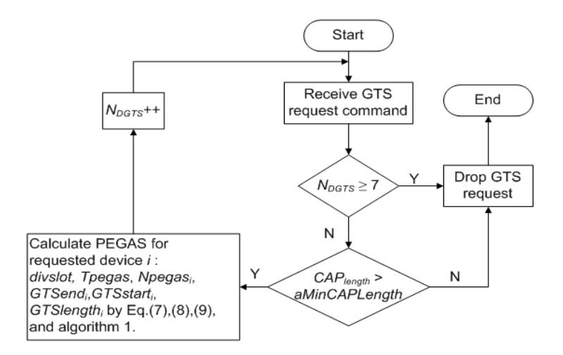
Figure 1 PEGAS flowchart.
For example, we consider a star topology network with one PAN coordinator, 7 device nodes, and the value of the superframe order (SO) equal to the beacon order (BO) is 6. Each device node transmits packets with a length (\(L_{packet}\)) of 960 bits. The value of LIFS and the ACK packet are 160 bits and 88 bits, respectively. By using Eq. (7), we get a divslot value of 13.
If each node requests one GTS in IEEE 802.15.4, the number of slots needed for CFP is 7, as shown in Figure 2.
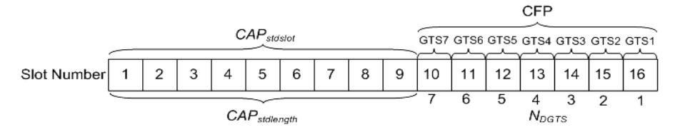
Figure 2 Example of GTS allocation in IEEE 802.15.4.
In PEGAS, the number of slots needed for CFP is not more than one out of 16 slots. Furthermore, if there are more than 7 device nodes, the device nodes that are not allocated a GTS can transmit more data packets in the CAP period because the CAP duration of PEGAS (CAPpegaslength) is increased as shown in Figure 3.
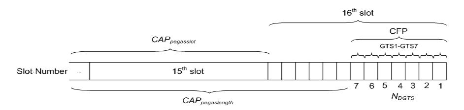
Figure 3 Example of GTS allocation in PEGAS.
By using PEGAS, the CFP period in the superframe is effectively reduced and bandwidth utilization is increased. Vice versa, more devices that could not get GTS allocation can increase their data packet transmission in the CAP because the CAP duration is increased.
3 Performance Evaluation
In this section, we report the performance evaluation of PEGAS obtained through simulation experiments by using the extended Castalia simulator [13]. The performance parameters included the total number of transmitted packets, throughput, energy efficiency, latency, bandwidth utilization of GTS, and CAP length ratio.
We considered a star topology with N nodes including one PAN coordinator, the first value of SO equal to BO was 6, the second value of SO equal to BO was 8, the packet length (Lpacket) was 960 bits, long interframe spacing (macMinLIFSPeriod) was 160 bits, the ACK packet length (Lack) was 88 bits, the simulation time was 100 seconds, the bit data rate (Rb) was 250000 bps. The traffic load was equal to ((N-1) x r x Lpacket)/Rb, where r is the packet arrival rate for each device in packets per second in the form of a Poisson stream. In this simulation, we considered the body area network radio in the Castalia simulator, where the transmitting power, the receiving power, and the sleep power were 3.0 mW, 3.1 mW, and 0.05 mW, respectively. In the figures of the performance evaluation "Stand WO GTS" denotes the IEEE 802.15.4 standard without GTS allocation, "Standard GTS" denotes the IEEE 802.15.4 standard with GTS allocation, and "PEGAS" denotes the proposed scheme.
Figures 4 to 9 show the results of the performance measurements while the number of nodes was 20 and the traffic load was from 0.1 to 1.
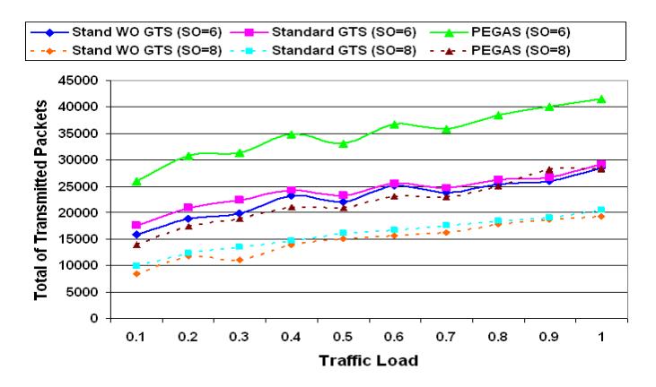
Figure 4 Traffic load against total number of transmitted packets (N = 20).
Figure 4 shows the traffic load against the total number of transmitted packets. The total number of transmitted packets was measured as the number of packets that can be transmitted from the device nodes to the PAN coordinator, both in CAP and CFP (GTS period). PEGAS obtained a higher total of transmitted packets than Standard WO GTS and Standard GTS due to its efficiency in using GTS allocation. The CAP duration of PEGAS was longer than that of Standard GTS, thus, more packets could be transmitted.
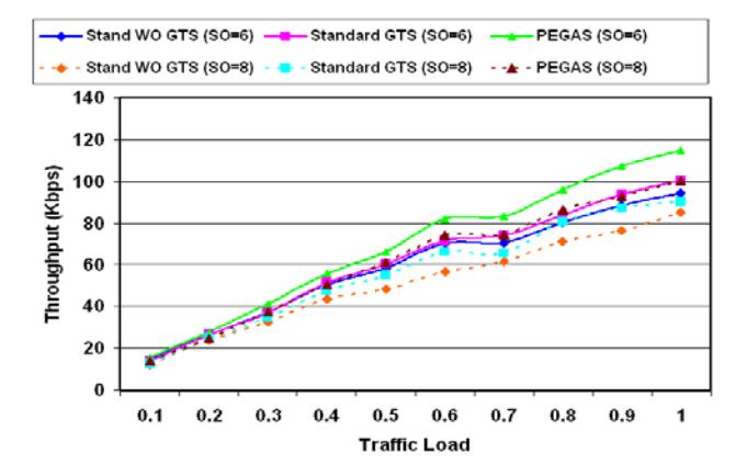
Figure 5 Traffic load against throughput (N = 20).
Figure 5 represents traffic load against throughput. The throughput is the number of packets per second that were successfully received by the PAN coordinator. The throughput of standard GTS was higher than without GTS.
However, the throughput of PEGAS was higher than that of standard GTS and without GTS due to the efficiently allocated GTSs for requested device nodes in PEGAS. Furthermore, the opportunity of packet transmission for device nodes in PEGAS that do not receive GTS to transmit packets in CAP was increased.
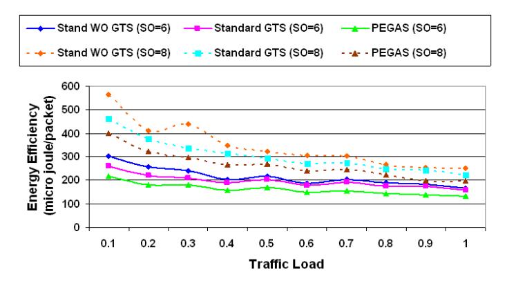
Figure 6 Traffic load against energy efficiency (N = 20).
Figure 6 shows traffic load against energy efficiency. The energy efficiency is measured from the total number of transmitted packets divided by the energy consumption in micro-joules per packet. The energy consumption of each packet of PEGAS was lower than that of Standard WO GTS and Standard GTS. Energy consumption increases if a device retransmits its data packet transmission because a device does not receive enough bandwidth during CFP or enough transmission time in CAP. However, PEGAS can reduce packet retransmission in CAP due to the sufficiency of the CAP duration and the efficiency of the GTS length.
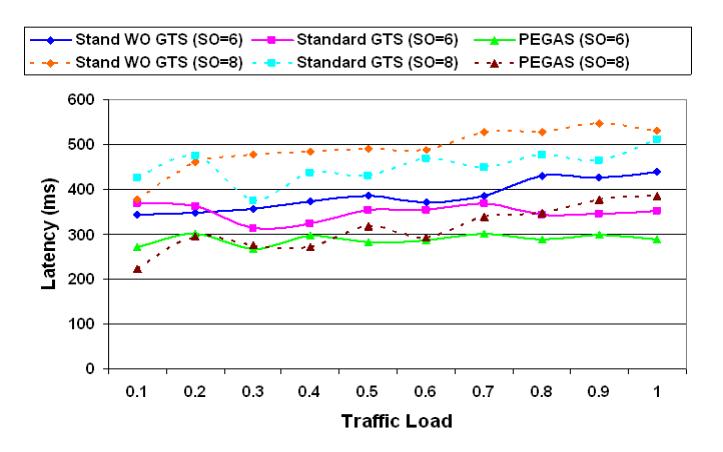
Figure 7 Traffic load against latency (N = 20).
Figure 7 provides the measurement of traffic load versus latency. Latency is defined as the time delay for data packet transmission of data packets generated by the device node to successful reception by the PAN coordinator. The latency decreases if a device node receives a precise GTS allocation or enough time to transmit in CAP, and thus it does not need to retransmit packets. It is obvious that the latency of PEGAS was smallest compared to Standard WO GTS and Standard GTS.

Figure 8 Traffic load against bandwidth utilization of GTS (N = 20).
Figure 8 shows traffic load versus bandwidth utilization of GTS. The bandwidth utilization of GTS is the utilization ratio of GTS allocation that can be obtained using Eq. (6) for bandwidth utilization of the IEEE 802.15.4 standard and Eq. (10) for bandwidth utilization of PEGAS. PEGAS gains more efficient bandwidth utilization of GTS. In the IEEE 802.15.4 standard with the value of SO equal to 6, each device requests one slot for GTS at traffic load from 0.1 to 0.9. However, it request two slots for GTS while traffic load is equal to 1, thus, the bandwidth utilization degrades.
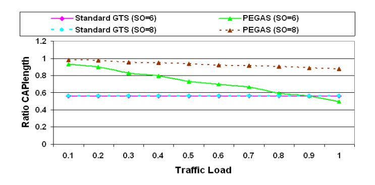
Figure 9 Traffic load against ratio CAP length (N = 20).
Figure 9 shows traffic load versus CAP length ratio. The CAP length ratio is obtained from Eq. (13) divided by Eq. (1) for the CAP length ratio of the IEEE 802.15.4 standard, and from Eq. (14) divided by Eq. (1) for the CAP length ratio of PEGAS. The CAP length ratio of PEGAS is higher than that of the IEEE 802.15.4 standard. In other words, PEGAS utilizes CFP allocation more efficiently than the IEEE 802.15.4 standard.
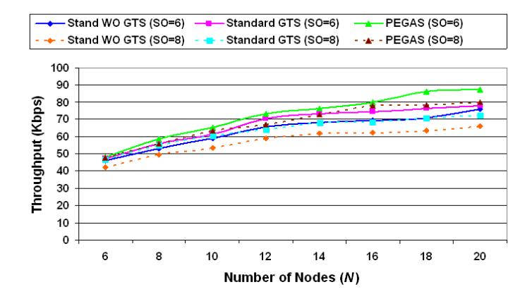
Figure 10 Number of nodes against throughput (traffic load = 0.5).
Figures 10 and 11 show the results of the performance measurements while the traffic load was 0.5 and the number of nodes was from 6 to 20 nodes. It is obvious that the result of the totals of throughput and latency of PEGAS were better than those of IEEE 802.15.4.
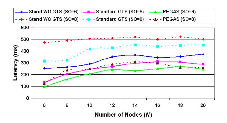
Figure 11 Number of nodes against latency (traffic load = 0.5).
Based on the above results from the PEGAS algorithm and related works, we have considered seven parameters to show the contribution of the PEGAS
algorithm to analyze the quality of service of GTS comprehensively, as shown in Table 2.
| Table 2 | Comparison between Algorithms from PEGAS and Related Works. |
|---|
| Algorithm | Topology | Traffic | Throughput | Efficiency Energy | Latency | Bandwidth Utilization | Fairness |
|---|---|---|---|---|---|---|---|
| Huang [2] | Star | Poisson | No | No | Yes | No | Yes |
| Cho [3] | Star | Poisson | Yes | No | Yes | No | No |
| Shrestha [4] | Star | Impulsive or Bursty | No | No | No | Yes | Yes |
| Cheng [5] | Star | NA | No | No | No | Yes | No |
| Hong [6] | Star | Periodic | No | No | No | Yes | No |
| Seo [7] | Star | Periodic and Bursty | Yes | No | Yes | No | No |
| Ding [8] | Star | Periodic | No | Yes | Yes | Yes | No |
| Chen [9-10] | NA | NA | No | No | Yes | Yes | No |
| Shah [11] | Star | NA | Yes | No | N | Yes | No |
| PEGAS | Star | Poisson | Yes | Yes | Yes | Yes | Yes |
4 Conclusion
In this paper, we have proposed PEGAS for IEEE 802.15.4 networks. The goals of PEGAS are to decide the precise moment for the starting time (GTSstart), the end (GTSend), and the length of the GTS allocation (GTSlength) for requested devices taking into account the value of superframe order (SO), superframe duration (SD), length of data packet, and arrival data packet rate in order to alleviate the waste of GTS bandwidth utilization. PEGAS is expected to effectively allocate GTS to the requested devices, while at the same time, the length of the CAP is also adequate for devices that do not receive an allocated GTS to transmit their data packets. The simulation experiments and analysis results showed that the PEGAS algorithm performed better than the IEEE 802.15.4 standard in terms of total number of transmitted packets, throughput, energy efficiency, latency, bandwidth utilization, and contention access period (CAP) length ratio.
Acknowledgements
This research was supported by the Directorate General of Higher Education (DIKTI) of Indonesia.