
1 Introduction
The rapid progress in mobile and wireless technology has increased the need of integrating more than one communication standard or technology into a single system [1-11] where different standards may operate in different frequency bands. Multiband radio frequency (RF) and microwave modules play an important role in a variety of modern communication systems. The microwave multiband bandpass filter (BPF) is one of the most important modules in the front-end circuit. Conventionally, in designing a multiband BPF, the principle of stepped impedance resonators (SIRs) is often used as a building block, due to their multiband behavior, simple structure and well-established design methodology [2-4]. However, the resonance frequencies of the SIRs are dependent on each other, the filter design is quite complicated and it is not convenient to meet specific bandwidth (BW) requirements.
To construct a triple-band microwave BPF, usually two or more SIRs of different resonance frequencies are needed due to the dependence of the third resonance frequency on the first two SIRs [5]. This method results in a large circuit and a complex BPF configuration. To reduce the circuit size and to add design flexibility, a tri-section SIR (TSSIR) with tunable first three resonance frequencies was proposed by Zang, et al. [7]. It was indicated in Packiaraj, et al. [8] that under the same demanded filter specifications, the electric length of a TSSIR can be designed shorter than that of a two-section SIR.
Triple-band TSSIR BPFs using a hairpin structure were designed and evaluated by Chu, et al. [1], Eroglu, et al. [2] and Wibisono, et al. [10]. However, the triple-band TSSIR using a hairpin structure has a stop-band rejection characteristic that does not satisfy the requirements and the BW of the first band has a narrow band [10]. This is due to the fact that the coupling of the filter happens only at one resonator; otherwise, the input/output port is connected to the third resonator, hence the BW of the first band is narrow.
In this research, a triple-band BPF using cascade TSSIR was designed, fabricated and analyzed. The cascade TSSIR BPF is proposed as an enhancement of the conventional TSSIR [5] in order to improve the stopband rejection response of the hairpin TSSIR [10]. Implementation of the cascade TSSIR is done using two TSSIRs that are coupled to each other in the third resonator. The structure is designed to get transmission zero response at the third band. Thus, the stopband response is improved. To get a wider BW and improve the first frequency response, the input and output ports are connected to the first resonator. The performance parameters of the proposed BPF were characterized by insertion loss (S21), return loss (S11), voltage standing wave ratio (VSWR) and group delay. The performance results from the simulation were compared to those of the fabricated BPF.
The design and research methodology are detailed in the following sections. Section 2 describes the design of the proposed BPF using cascade TSSIR. Results and discussion of the performance test of the fabricated BPF are reported in Section 3. Finally, Section 4 concludes this paper.
2 Triple-Band BPF Design
To design a triple-band BPF, a TSSIR as an enhancement of the SIR was used. The TSSIR structure to be considered is shown in Figure 1 of [1], where the TSSIR has three different impedance characteristics: Z1, Z2, and Z3. For practical application this is preferable to having an equal electrical length. Then, the condition for the fundamental resonance of the TSSIR can be derived as reported in Chu, et al. [1], Eroglu, et al. [2] and Lin, et al. [5].
\[\theta = tan^{-1} \sqrt{\frac{K_1 K_2}{K_1 + K_2 + 1}} \tag{1}\] where \(K_1\) and \(K_2\) are the ratios of the impedance resonators represented by \(K_1 = Z_3/Z_2\) and \(K_2 = Z_2/Z_1\), respectively.
The total electrical length of the resonator at the fundamental resonance, \(\theta_T\), is given by Chu, et al. [1], Eroglu, et al. [2] and Lin, et al. [5]:
\[\theta_T = 6\theta = 6tan^{-1} \sqrt{\frac{K_1 K_2}{K_1 + K_2 + 1}} \tag{2}\]
The first spurious passband, "\(f_{s1}\)" (second passband), occurs at
\[f_{\rm S1} = \frac{\theta_{\rm S1}}{\theta} f_0 \tag{3}\] where
\[\theta_{s1} = tan^{-1} \sqrt{\frac{1 + K_1 + K_1 K_2}{K_2}} \tag{4}\] and, \(f_0\) is the zero spurious passband. The second spurious passband, "\(f_{s2}\)" (third passband), occurs at
\[f_{s2} = \frac{\theta_{s2}}{\theta} f_0 \tag{5}\] where
\[\theta_{S2} = \frac{\pi}{2} \tag{6}\]
From Eqs. (1), (3), and (4) we can obtain the first frequency ratio as expressed in Chu, et al. [1], Eroglu, et al. [2] and Lin, et al. [5]:
\[\frac{f_{s1}}{f_0} = \frac{\theta_{s1}}{\theta} = \frac{\tan^{-1}\sqrt{\frac{1+K_1+K_1K_2}{K_2}}}{\tan^{-1}\sqrt{\frac{K_1K_2}{K_1+K_2+1}}}\](7)
From Eqs. (1), (5) and (6) another frequency ratio can be expressed as in [1,5]:
\[\frac{f_{S2}}{f_0} = \frac{\theta_{S2}}{\theta} = \frac{\pi}{\tan^{-1} \sqrt{\frac{K_1 K_2}{K_1 + K_2 + 1}}} \tag{8}\]
By properly determining the impedance ratios of \(K_1\) and \(K_2\), three passbands with any desired frequency ratio can be obtained. The impedance ratios \(K_1\) and \(K_2\) can be derived according to the three desired frequencies \(f_0\), \(f_{s1}\), and \(f_{s2}\) of the passbands from Eqs. (7) and (8) as in [1,5]:
\[\begin{cases} K_{1} = \frac{-\cos\alpha\cos\beta + \sqrt{\cos^{2}\alpha\cos^{2}\beta + 4\sin^{2}s\cos^{2}(rs)}}{2\cos^{2}(rs)} \\ K_{2} = \frac{1 + K_{1}}{\tan^{2}(rs) - K_{1}} \end{cases}\](9)
where
\[r = \frac{f_{s1}}{f_0}\], \(s = \frac{\pi}{2} \frac{f_0}{f_{s2}}\), \(\alpha = \frac{\pi}{2} \frac{f_{s1} + f_0}{f_{s2}}\), \(\beta = \frac{\pi}{2} \frac{f_{s1} - f_0}{f_{s2}}\)
By determining the impedance ratios of \(K_1\) and \(K_2\), three different characteristic impedances, i.e. \(Z_1\), \(Z_2\), and \(Z_3\), can be obtained, where the characteristic impedance ZC is given by Hong, et al. [11]:
\[Z_c = \frac{60}{\sqrt{\varepsilon_{re}}} \ln \left[ \frac{F}{W/h} + \sqrt{1 + \left(\frac{2}{W/h}\right)^2} \right]\] (10)
where
\[F = 6 + (2\pi - 6)\exp\left[-\left(\frac{30.666}{W/h}\right)^{0.7528}\right]\]
The effective dielectric constant (\(\varepsilon_{re}\)) is given by Hong, et al. [11]:
\[\varepsilon_{re} = \frac{\varepsilon_{r+1}}{2} + \frac{\varepsilon_{r-1}}{2} \left( 1 + \frac{10}{W/h} \right)^{xy} \tag{11}\] where
\[x = 1 + \frac{1}{49} \ln \left( \frac{(W/h)^4 + \left(\frac{W/h}{52}\right)^2}{(W/h)^4 + 0.432} \right) + \frac{1}{18.7} \ln \left[ 1 + \left(\frac{(W/h)}{18.1}\right)^2 \right]\] and
\[y = 0.564 \left(\frac{\varepsilon_r - 0.9}{\varepsilon_r + 3}\right) 0.053\]
W is microstrip width and h is dielectric material thickness. The ratio of W/h is given by Hong, et al. [11]:
\[\frac{W}{h} = \begin{cases} \frac{8\exp(A)}{\exp(2A) \cdot 2} & W/h^{\leq 2} \\ \frac{\pi}{2} \left\{ (B-1) - \ln(2B-1) + \frac{\varepsilon_r - 1}{\varepsilon_r + 1} \left[ \ln(2B-1) + 0.39 - \frac{0.61}{\varepsilon_r} \right] \right\} & W/h^{\geq 2} \end{cases}\](12)
where
\[A = \frac{Z_c}{60} \left\{ \frac{\varepsilon_r + 1}{2} \right\} 0.5 + \frac{\varepsilon_r}{\varepsilon_r} \left( 0.23 + \frac{0.11}{\varepsilon_r} \right)\]
\[B = \frac{60\pi 2}{Z_c \sqrt{\varepsilon_r}}\]
The cascade TSSIR BPF is proposed as an enhancement of the TSSIR in order to improve the stopband rejection response of the triple band hairpin TSSIR from Wibisono, et al. [10]. The specifications of the proposed triple-band BPF using cascade TSSIR are the same as for the hairpin BPF in Wibisono, et al. [10], as shown in Table 1.
| Table 1 | Specifications of proposed triple-band BPF using cascade TSSIR. |
|---|
| Center Frequency (MHz) | 950 | 1,850 | 2,650 |
|---|---|---|---|
| BW (MHz) | 100 | 100 | 100 |
| Insertion Loss, S21 (dB) | > -3 | > -3 | > -3 |
| Return Loss, S11 (dB) | < -10 | < -10 | < -10 |
| VSWR | < 2 | < 2 | < 2 |
The structure of the proposed triple-band BPF using cascade TSSIR is shown in Figure 1. The proposed BPF using cascade TSSIR was constructed from two identical TSSIRs, which were coupled at the third resonator in order to achieve better stopband performance. To improve the BW value, the input/output port was connected at the first resonator. The proposed BPF using cascade TSSIR was designed to improve the performance of the hairpin BPF using TSSIR [10] and to minimize the hairpin structure. The dimensions of the proposed BPF using cascade TSSIR were obtained using the method employed in Lin, et al. [5] and Wibisono, et al. [10].
Figure 1 Layout of triple band BPF with cascade TSSIR.
The calculated dimensions of the proposed BPF using cascaded TSSIR were obtained using Eqs. (1)-(12). For comparison, the optimized dimensions of the proposed BPF using cascade TSSIR simulated using ADS are shown in Table 2. The optimized dimensions were simulated in order to find the fixed three frequency centers that can be operated by the proposed BPF. The calculated dimensions were close to the optimized dimensions. The total size of the proposed BPF was 5.4 x 7.03 cm2 , which is smaller than the size of the hairpin BPF in Wibisono, et al. [10].
Table 2 Comparison of dimensions of cascade TSSIR from calculation and optimized ADS.
| Size (mm) | ||||
|---|---|---|---|---|
| Dimension | Calculated | Optimized | ||
| W1 | 4.8596 | 5 | ||
| W2 | 5.0473 | 6.1 | ||
| W3 | 3.1118 | 3.1118 | ||
| L1 | 15.3507 | 15.3507 | ||
| L2 | 15.3238 | 16.2 | ||
| L3 | 15.6568 | 16 | ||
3 Simulation Results
The performance of the proposed BPF using cascade TSSIR was characterized by return loss (S11), insertion loss (S21), VSWR, and group delay. S11 expresses the input reflection coefficient to show the effectiveness of the BPF in transmitting the signal from the generator to the load. Meanwhile, S21 and VSWR were simulated to see if the proposed BPF will transmit all power from input to the output of the filter and not cause mismatch to the load, respectively. Group delay was simulated to show phase shift and distortion when the signal passes to the BPF.
Figure 2 shows the simulation results of S11 and S21 of the proposed BPF using cascade TSSIR. It can be seen from Figure 2 that the simulation results of S11 and S21 with center frequency at 950 MHz were -38.434 dB and -0.123 dB, respectively. The BW at a center frequency of 950 MHz was 107 MHz, or fractional BW (FBW) = 11.26 %. Here, FBW denotes the ratio between BW and center frequency. At a center frequency of 1,850 MHz, S11 = -40.426 dB, S21 = -0.161 dB, and BW = 299 MHz or FBW = 16.16 %. At a center frequency of 2,650 MHz, S11 = -41.196 dB, S21 = -0.135 dB, and BW = 425 MHz or FBW = 16.03%.
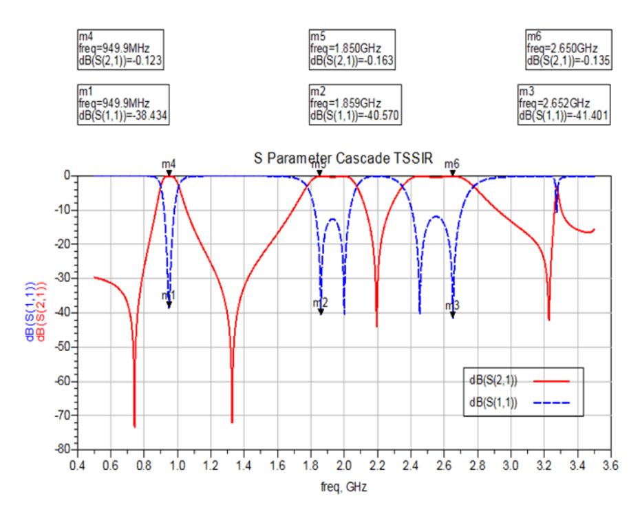
Figure 2 The S11 and S21 results of the simulated BPF using cascade TSSIR.
It can be seen from Figure 2 that the simulation results of S11 and S21 satisfied the design specifications, while BW performance was achieved only at the center frequency of 950 MHz. The results showed that S11 performance was < -10 dB. This means that the proposed BPF can transfer all power from input to output of the BPF; there was no reflection signal back to the input BPF. The input impedances of the proposed BPF were Z0*(1.019 – j0.094) at a center frequency of 950 MHz, Z0*(1.092 + j 0.040) at a center frequency of 1,850 MHz, and Z0*(0.983 – j0.144) at a center frequency of 2,650 MHz, respectively, where Z0 is the impedance characteristic. These input impedances indicate that the reflection signal back to the input BPF was very small (near to zero). This is also because the cascade construction was successful in getting transmission zero response at the third band. Thus, the stopband response was improved, indicated by the very small value of S11. It can be concluded that the proposed BPF matched the transmission line input and can operate properly at three different frequencies simultaneously.
The S21 performance values were near to 0 dB, which means that the proposed BPF can transmit all the power to the load and dissipates less power at the BPF. It can be concluded that the proposed BPF using cascade TSSIR can be operated well at center frequencies of 950 MHz, 1,850 MHz and 2,650 MHz simultaneously.
Figure 3 shows the VSWR simulation results of the proposed BPF using cascade TSSIR. It can be seen from Figure 3 that the VSWRs of the proposed BPF were 1.024, 1.158 and 1.029 at center frequencies of 950MHz, 1,850 MHz and 2,650 MHz, respectively. All three VSWRs were in close agreement with the design requirements. It was found that the S21 performances of the proposed BPF had value > -2 dB, which indicates that all signals were passed by the BPF at three frequencies simultaneously. This is because the proposed BPF has input and output impedances that match each other. Therefore, the VSWR values of the proposed BPF were close to 1.00 and the proposed BPF can be operated well at three frequencies simultaneously.
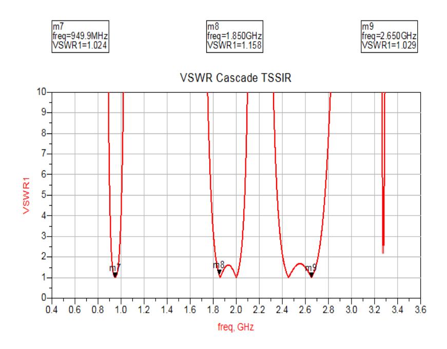
Figure 3 The VSWR results of the simulated BPF using cascade TSSIR.
Figure 4 shows the simulation results of the group delay of the proposed BPF using cascade TSSIR. It can be seen from Figure 4 that the group delay results were 3.67, 1.47 and 0.83 ns at center frequencies of 950 MHz, 1,850 MHz, and 2,650 MHz, respectively. All three group delays were in close agreement with the design requirement. This indicates that the proposed BPF can operate well at three frequencies simultaneously, not causing significant phase shift and distortion when the signal passes to the filter. This occurs because the proposed
BPF has good S21 and VSWR performances, so there was no significant distortion as indicated by group delay < 10 ns. It can be concluded that the proposed BPF using cascade TSSIR can be operated well at three frequencies simultaneously.
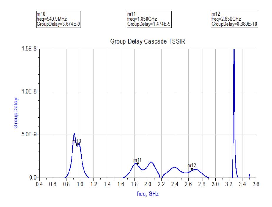
Figure 4 The group delay results of the simulated BPF using cascade TSSIR.
Table 3 Performance results of simulated results of proposed BPF using cascade TSSIR.
| Parameters | BPF Using Cascade TSSIR | |||
|---|---|---|---|---|
| Center Frequency (MHz) | 950 | 1,850 | 2,650 | |
| S21 (dB) | - 0.12 | - 0.16 | - 0.14 | |
| S11 (dB) | - 38.43 | - 40.57 | - 41.40 | |
| VSWR | 1.02 | 1.16 | 1.03 | |
| BW (MHz) | 107 | 299 | 425 | |
| FBW (%) | 11.26 | 16.16 | 16.03 | |
A summary of the performance results of the proposed BPF using cascade TSSIR is shown in Table 3. It can be seen from Table 3 that the performance results of the proposed BPF satisfy the requirement performances as given in Table 1.
4 Fabricated BPF Results
The proposed BPF using cascade TSSIR was fabricated on FR4 substrate with dielectric permittivity, substrate thickness and loss tangent at 4.3, 1.6 mm and 0.0017, respectively. Figure 5 shows the fabricated version of the proposed BPF using cascade TSSIR. The three passbands of the proposed BPF using cascade TSSIR were located at center frequencies of 950 MHz, 1,850 MHz, and 2,650 MHz. The fabricated BPF using cascade TSSIR had smaller dimensions than those of the hairpin BPF using TSSIR as proposed in [10].
Figure 5 The fabricated BPF with cascade TSSIR.
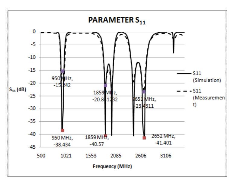
Figure 6 S11 results of the fabricated BPF using cascade TSSIR.
Figure 6 shows the S11 measurement results of the proposed BPF using cascade TSSIR. It can be seen from Figure 6 that the S11 performance of the fabricated BPF was in close agreement with the design requirement. This is due to the cascade construction being successful in getting transmission zero response at the third band. Therefore, the stopband response was improved. This indicates that the proposed BPF using cascade TSSIR can operate well at three frequencies simultaneously.
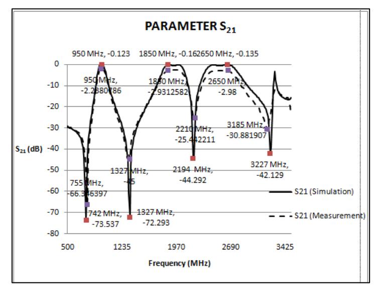
Figure 7 S21 results of the fabricated BPF using cascade TSSIR.
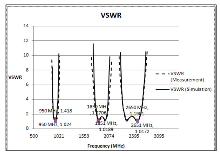
Figure 8 VSWR results of the fabricated BPF using cascade TSSIR.
Figure 7 shows a comparison of the S21 results of the simulated and the fabricated BPF using cascade TSSIR. It can be seen from Figure 7 that the S21 results of the fabricated BPF using TSSIR was in close agreement with the design requirement. This is because the proposed BPF using cascade TSSIR is successful in generating three passbands, hence it can transmit all power to the load and dissipates less power at BPF. It can be concluded that the proposed BPF using cascade TSSIR can be operated well at three frequencies simultaneously.
Figure 8 shows a comparison of the VSWR performance results of the simulated and the fabricated BPF. It can be seen from Figure 8 that the VSWR of both the simulated and the fabricated BPF satisfied the design specification, which was VSWR < 2. This is because the input and output impedances match with each other, so the proposed BPF using TSSIR was successful in passing all signals to the load at three frequencies simultaneously. It can be concluded that the proposed BPF using cascade TSSIR can be operated well at three frequencies simultaneously.
For comparison, the performance results of the simulated and the fabricated triple-band BPF using cascade TSSIR are shown in Table 4. It can be seen from Table 4 that performance results of the simulated and the fabricated triple-band BPF using cascade TSSIR were in close agreement with each other. This indicates that the proposed BPF using cascade TSSIR can operate well at three frequencies simultaneously.
Table 4 Comparison of performance results of simulated and fabricated tripleband BPF with cascade TSSIR.
| Parameters | Simulated | Fabricated | ||||
|---|---|---|---|---|---|---|
| fc (MHz) | 950 | 1,850 | 2,650 | 950 | 1,850 | 2,650 |
| S21 (dB) | -0.12 | -0.16 | -0.14 | -1.04 | -1.73 | -1.78 |
| S11 (dB) | -38.43 | -40.57 | -41.40 | -15.24 | -20.84 | -23.43 |
| VSWR | 1.02 | 1.16 | 1.03 | 1.42 | 1.27 | 1.19 |
The performances of the proposed triple-band BPF using TSSIR were better than the performances of the hairpin BPF using cascade TSSIR in Wibisono, et al. [10]. This is due to the construction of the proposed triple-band BPF using TSSIR, which was designed from two identical TSSIRs that are coupled at the third resonator and was successful in getting transmission zero response at the third band, so better stopband performance could be achieved. Also, the input/output port connected at the first resonator was successful in improving the BW of the proposed triple-band BPF using TSSIR.
5 Conclusion
A triple-band BPF using TSSIR that can operate at 900 MHz, 1,800 MHz and 2,600 MHz simultaneously was designed, fabricated and evaluated. The design and simulation of the proposed BPF were done using ADS. The proposed BPF using cascade TSSIR was fabricated on FR4 substrate with dielectric permittivity, substrate thickness and loss tangent at 4.3, 1.6 mm and 0.0017, respectively. It can be seen from the results that the performance results of both the simulated and the fabricated BPF using cascade TSSIR, characterized by return loss, insertion loss, VSWR and group delay, satisfied the performance standard and were in close agreement with each other. In addition to this, the results showed that the performances of the proposed BPF using cascade TSSIR were better than those of a hairpin BPF with TSSIR.
Acknowledgements
This research was supported by National Strategic Research Grant from Directorate Higher Education (DIKTI) Ministry of National Education of Republic Indonesia, 2012.