
1 Introduction
In this paper we describe the use of our product-service-system (PSV-S) approach in prototyping digital signal processing systems virtually, using software platforms [1]. The PSV-S concept was originally developed to cover product, service and value systems. The main purpose of this paper is to validate the use of PSV-S in DSP product development. Speech coder algorithms are of special interest because they can be mapped into values, services and products [2]. Speech quality and intelligibility are the values to be preserved. Speech transformations from speech samples to bitstreams suitable for low bit rate transmissions and back are the services to be provided. Finally, the DSP chips or hardware modules are the products to be packaged.
Economic considerations put an emphasis on short time to market, demanding rapid developments of single-chip DSP systems [3,4]. Our virtual prototyping is an approach for rapid development. It consists of four iterative development phases: (1) a generic DSP system, (2) a functional DSP system, (3) an architectural DSP system, and (4) a real-time DSP system.
This paper reports the application of the iterative development phases on a DSP starter kit (DSK) platform supported by Code Composer technology as a generic DSP system [5-7]. The target is to produce a single-chip product that performs speech-to-bistream conversions (from 64 kbit/s samples to 8 kbit/s or less bitstreams) while maintaining speech quality (signal-to-noise ratios of more than 10dB). First, PSV-S and its engineering are explained in Section 2. Section 3 describes the DSK as a generic platform to perform speech coding. Section 4 then shows an algorithm with which the speech codec can reduce the bit rates while maintaining speech quality. Section 5 describes the architecture of the DSP chip to be used, as well as an optimiziation effort to fit the algorithm into the architecture. In Section 6, we discuss the results and their implications for obtaining a real-time single-chip DSP speech coder. Section 7 provides our concluding remarks.
2 Overview of PSV-S for PSV-S Virtual Prototyping
A PSV-S is a model of entities with three perspectives: product, service, and value [5]. As shown in Figure 1, the system maintains an internal value, serves a value source and a value receiver within a value environment. Its objective is to increase values stored in the source and the receiver while maintaining environmental support and a positive internal value. This objective is accomplished through currency exchanges of up to six currencies, namely solution value, price value, cost value, revenue value, external value, and external cost.
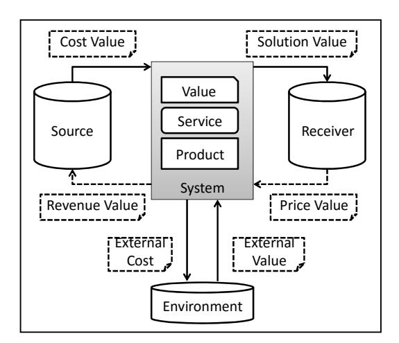
Figure 1 PSV-S exchanges currencies between source and receiver supported by the environment.
We have shown that a special PSV-S can engineer a PSV-S under design (PSV-S UD). As shown in Figure 2, the source develops the PSV-S UD using a development process according to required performance. The receiver then evaluates the actual performance. If the performance is acceptable, the PSV-UD becomes the engineering result. Otherwise the receiver issues various feedbacks and adjustment requirements; the source repeats the process.
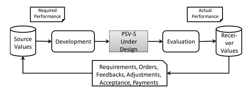
Figure 2 PSV-S for engineering PSV-S UD.
In essence, the engineering process compresses its value into an efficient form. We have a selection of three known value compression approaches: compaction, minimizing and substitution. As shown in Figure 3, value compaction finds a more efficient representation of the solution value. Value minimizing excludes less important values. Value substitution replaces the value with a new one that is more efficient.
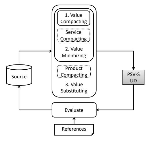
Figure 3 PSV-S engineering compresses the source values into a PSV-UD.
PSV-S modelling and engineering lend themselves naturally to virtual prototyping. PSV-S abstractions can be expressed using computing language. Figure 4 shows how the requirements can be coded using a computational system description. In turn, we generate a PSV-S behavioural model as well as its input and output references. Here all value, service and product aspects of the PSV-S behaviour have to be described.
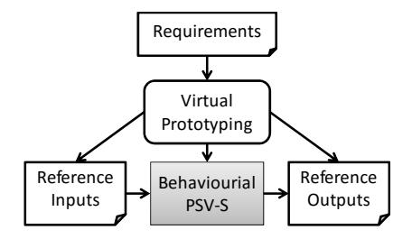
Figure 4 Virtual prototyping of PSV-S UD.
Thus in virtual prototyping, PSV-S UD evolves computationally through various processes according to Figures 2 and 3, starting with the process in Figure 4. As shown in Figure 5, the PSV-S UD evolution process starts with a generic computing model, moving to a functional model, an architectural model, and finally a realistic form. Here we maintain a repository of various models and components to be used in subsequent development. External PSV-Ss are a source of new innovations being absorbed by the PSVS-UD.
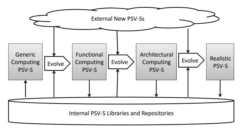
Figure 5 The PSV-S UD evolves from conceptual model into physical realization.
3 DSP Starter Kit as Generic Prototype
In this speech codec project we selected a DSP Starter Kit (DSK) as the generic PSV-UD. As shown in Figure 6, the DSK has analog I/O ports for user speaker and microphone, UART I/O for digital channel communications, and a TMS 320C5402 processor. The memory bank has a size of 128 kbyte SRAM and 256 kbyte Flash RAM, sufficient for hosting the program code. Speech sound can be captured by analog I/O into 64 kbits/s samples. The DSP engine uses a program stored in the memory bank to encode the speech samples into bitstreams at bit rates as low as 8 kbits/s or less.
Figure 6 DSK module (source: Texas Instruments).
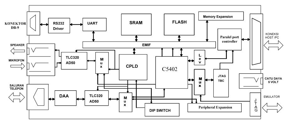
Figure 7 DSK internal block diagram (source: Texas Instruments).
From a development perspective, we are interested in the logical scheme of the DSK, as shown in Figure 7. The audio section, consisting of an ADC/DAC for speaker and microphone and a phone DAA link, connects to the serial port of the DSP processor. The digital serial channel connects through a high-speed EMIF channel. This means input and output run separate channels, allowing a low-latency speech transcoder. A JTAG port connects to a host PC allowing the developer to communicate with the DSP processor.
As mentioned before, this DSK is supported by Code Composer, a code integrated development environment (IDE) in which the developer can write C code, compile it into DSP machine code and then load it to a DSK for execution. The developer can debug the code in real-time through a JTAG connection. One can use Code Composer to view how each C code line has been compiled into a series of machine codes, as shown in Figure 8. One can also view the assembly code as it occupies the program memory. While executing the program, one can see the dynamics of the internal registers of the DSP processor step-by-step.
Figure 8 Code Composer as a PC-based code development program supporting DSK (source: Texas Instruments).
Using Code Composer and a DSK, we can set up the basic behavioural prototype (generic speech codec prototype). The C code consists of two parts: analysis and synthesis. The analysis part reads a file containing speech samples. We use two files: a short one, TEST.INP (1.76s), and a longer one, DAM9.INP
(21.48s), as input samples. The TEST.INP file is an ITU-T speech file for testing G.729, containing a male-spoken segment in the French language. The DAM9.INP file is the US Department of Defense (DoD) file for testing CELP, containing a mix of male and female spoken rhyme sentences in English. The analysis program produces bitstream files TEST.BIT and DAM9.BIT, respectively. The synthesis program takes the bistreams and reproduces the speech samples files TEST.OUT and DAM9.OUT, respectively.
We can then measure the performance of the system. First, we take the size of TEST.BIT and DAM9.BIT and ensure that both correspond to a rate of 8 kbps or less. Next, we compare both original samples and reproduced samples, and ensure the signal-to-noise ratio (SNR) is higher than 10 dB. In addition to the prototype code, we added support code to perform the measurements.
4 Functional Prototype
We developed the generic prototype into a functional prototype that satisfies (1) bit rate requirements, and (2) quality requirements. From a PSV-S perspective, these are the value requirements. The lower the bit rates, the higher the PSV-S value; the higher the SNR the higher the PSV-S value. Both are achieved simultaneously using a compression scheme. In this project we selected the MP-MLQ/ACELP codec [8], explained briefly as follows.
4.1 Reducing Bit Rates: Synthesis
The MP-MLQ/ACELP codec achieves low bit rates by using a speech synthesizer to produce speech samples. As shown in Figure 9, a synthesizer can reproduce speech samples using a pitch and synthesis filter. An excitation decoder and pitch decoder generate excitation of the synthesis filter to produce the speech samples. A post-processing block improves speech reproduction quality to produce the output speech.
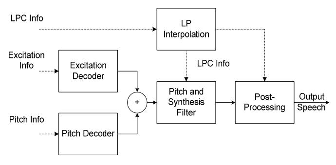
Figure 9 Speech synthesizer of MP-MLQ/ACELP codec.
The synthesizer needs three kinds of information to produce speech, namely LPC bits, pitch bits and excitation bits. As shown in Table 1, for every 30 ms of speech the parameters need 189 bits and 158 bits for MP-MPQ and ACELP, respectively. These bit requirements translate into 6.3 kbit/s and 5.3 kbit/s, respectively; they satisfy the original requirement of bit rates.
| Parameters | Details | MP-MLQ (Bits) | ACELP (Bits) |
|---|---|---|---|
| LPC | LPC Indices | 28 | 24 |
| Excitation | Adaptive CB Lags | 18 | 18 |
| Gain | 48 | 48 | |
| Pitch | Pulse Positions | 73 | 48 |
| Pulse Signs | 22 | 16 | |
| Grid Index | 4 | 4 | |
| Total | 189 | 158 |
Table 1 Bits requirements for 30 ms Speech (ITU-T G.723.1).
4.2 Increasing Quality: Analysis
Given such a low bit-rate bit allocation, it is important to ensure the best speech quality. This is accomplished by LPC analysis, as shown in Figure 10. Speech samples are collected in 30-ms blocks. LPC analysis of a block results in LPC information bits. Pitch and excitation information bits are obtained by openloop and closed-loop analysis. An open-loop scheme obtains coarse pitch information. Furthermore, a closed loop process refines the pitch information.
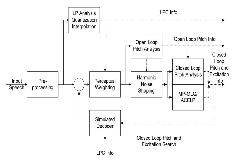
Figure 10 Speech synthesizer of MP-MLQ/ACELP codec.
The closed-loop process finds excitation information through codebook searching, minimizing the energy of error. The purpose of the search is to find the best pitch and excitation parameters that when applied to a simulated decoder produce the lowest error energy. The LPC information is used to enhance the speech quality by compensating perceptual aspects into the energy measurement. Such a closed-loop approach ensures the highest quality of reconstructed speech.
ITU-T provides a reference code implementing both the synthesizer and the analyser [8]. We have adopted the code into our generic prototype, resulting in the functional prototype. When simulated, the functional prototype produces the files TEST.BIT and DAM9.BIT, whose sizes conformed to bit rates of 6.3 kbit/s and 5.3 kbit/s.
Furthermore, we also measured the quality of the synthesized speech, as shown in Table 2. Both schemes performed at an SNR of more than 11 dB. The results also confirmed the quality advantages of MP-MLQ over ACELP.
The functional prototype code was run on the DSK. It took 36,589 words and 20,446 words for program and data, respectively. This total of 56.9 Kword fits into the DSK but does not fit into the single-chip internal memory of the TMS320C5409 processor, which has only 48 Kword internal memory.
Table 2 Resulting speech SNR quality.
| Original (64 kbit/s) | MP-MLQ (6.3 kbit/s) | ACELP (5.3 kibt/s) |
|---|---|---|
| TEST.INP | 12.30 dB | 11.30 dB |
| DAM9.INP | 13.14 dB | 11.73 dB |
| Averaged SNR | 12.72 dB | 11.52 dB |
Furthermore, Table 3 shows million instructions per second (MIPS) requirements for MP-MLQ and ACELP. MP-MLQ requires 2707 MIPS while ACELP 2055 MIPS. They are too high for real-time implementations. A TMS 320C5409 for example has 100 MIPS only. Hence, the functional prototype would need more than 20 DSP processors to achieve the real-time requirements.
Table 3 MIPS requirements of the functional prototype.
| Rates | Encoder | Decoder | Total |
|---|---|---|---|
| MP-MLQ 6.3 kbps | 2554 | 153 | 2707 |
| ACELP 5.3 kbps | 1902 | 153 | 2055 |
5 Architectural Prototype
We then developed the functional prototype to match the DSP internal architecture. The main objective was to reduce both the memory and MIPS requirements to match the TMS320C5409 single-chip capacity. Code Composer was used to optimize the functional prototype code to match the TMS 320C5409 architecture, as follows:
- 1. Replace all C arithmetic functions with DSP assembly instructions.
- 2. Simplify all long and nested loops using DSP loop and repeat instructions.
- 3. Utilize indirect addressing mode to take advantage of dual access internal memory, allowing a full-capacity single-cycle pipeline.
- 4. Use circular buffers and circular addressing mode for filter functions
- 5. Use specialized built-in signal processing instructions such as LMS, FIR, POLY, NORM, ABDST, and SQDST.
- 6. Use high-speed internal memory for minimum access time and full pipeline support.
The process was repeated for many cycles, while maintaining the correctness of the optimized code. At the end of these cycles we measured the memory requirements as well as the MIPS requirements. The architectural prototype took 26,894 words and 12,159 words for program and data, respectively. This total of 39 Kwords of memory requirements now fitted into a single TMS320C5409 internal memory of 48 Kwords.
Furthermore, we could match the MIPS requirements, as shown in Tables 4 and 5. Here we measured them with various options, i.e. high pass filter, post filter and voice activation detection. All options required between 58.5 and 73 MIPS. They now fitted within the 100 MIPS capacity of the TMS320C5409. Hence the architecture prototype could fit and run in real-time on a single-chip DSP.
Table 4 MIPS requirements of MP-MLQ architectural prototype.
| Setting | Encoder | Decoder | Total |
|---|---|---|---|
| HP, PF, VAD off | 56.6 | 5.5 | 62.1 |
| HP and PF on; VAD off | 54.9 | 7.9 | 62.8 |
| HP, PF, and VAD on | 65.1 | 7.9 | 73.0 |
Table 5 MIPS requirements of ACELP architectural prototype.
| Setting | Encoder | Decoder | Total |
|---|---|---|---|
| HP, PF, VAD off | 53.4 | 4.9 | 58.3 |
| HP and PF on; VAD off | 55.8 | 7.6 | 63.4 |
| HP, PF, and VAD on | 62.3 | 7.5 | 69.8 |
6 Discussions of Realistic Demonstration Prototypes
Having developed the architectural prototype, we were ready to demonstrate a realistic prototype. Here we used the architectural prototype code for the analyzer and synthesizer. However, we had to add overall system considerations, mainly controller, speech input/output, and bitstream transmissions. Furthermore, a set of buffers was prepared for speech samples and bitstream transmissions. Timing and framing of samples is crucial.
First we set up one DSK to run the prototype code in a loop. Here, a microphone and a speaker were connected to the DSK. The DSK then analyzed the speech samples into bitstream and used the resulting bitstream to synthesize the reconstructed speech. We confirmed both the quality and the realtime requirements through subjective listening.
We set up two DSKs and connected their UART port accordingly so they could communicate at low bit rates. Furthermore the audio I/O ports of both DSKs were connected to speakers and microphones. The controller then activated each DSK so we could confirm full-duplex communications.
The main concern of the realistic prototype was the delay. Long delays cause both conversational inconvenience as well as failures of echo cancellation. It is desirable to have speech with a maximum algorithmic delay of less than 100 ms. As shown in Table 6, the delay caused by the algorithm was 37.5 ms because the algorithm had to wait for 37.5 ms (30 ms block size + 7.5 ms look ahead) samples in the buffer before it could proceed with the computation. The processing itself caused processing delay. The encoder introduced (65.1 MIPS / 100 MIPS) * 30 ms = 19.53 ms, while the decoder took (7.9 MIPS / 100 MIPS) * 30 ms = 2.37 ms. Hence, total delay was 37.5 ms + 19.53 ms + 2.37 ms = 59.4 ms, which is still well within the desired range.
Delay Sources Duration (ms) Notes Standard buffering 30.0 Fixed, 4 subframes Look ahead 7.5 Fixed, 1 subframe Encoding 19.5 Varies Decoding 2.4 Varies Total 59.5
Table 6 Implementation algorithmic delay.
Furthermore, when the chip is used in an actual system, there will be additional sources of delay. For example, Table 7 summarizes a GEO satellite case. ADC and DAC will introduce a delay of one sample. A 9.6 kbps modem could have a 39.4-ms delay. A GEO satellite will introduce a 135-ms delay per trip, totaling 260 ms. A total delay of 369.05 ms is still acceptable for satellite applications.
| Delay Sources | Duration (ms) | Notes |
|---|---|---|
| Mic and speaker | 0.0 | Negligible |
| ADC & DAC | 0.25 | One sample |
| Encoding + decoding | 59.4 | (see above) |
| Modem | 39.4 | 9.6 kbps UART |
| Transmission | 270 | GEO satellite |
| Total | 369.05 |
Table 7 System delay for a case of a satellite transmission.
7 Conclusions
This paper shows that a PSV-S approach is suitable for DSP system development. In this speech coding project, the values were speech bit rates and speech quality. The service was speech coding between user speech samples and channel bitstreams. The products were a DSK and a single-chip DSP. In particular, the DSK was used as a generic prototype at the beginning of an evolutionary process of virtual prototyping.
Our DSP development was a closed-loop iterative process. Here we started with a DSK as a generic speech prototype. The C code of the MP-MLQ and ACELP analyzer and synthesizer became the functional prototype. DSP code that was optimized for the TMS 320C5409 DSP processor was the architectural prototype. Finally, we integrated the optimized DSP code with speech I/O and channel I/O code into the DSK and configured demonstration systems. The realtime demonstration systems were realistic prototypes.
The whole system evolution took place in a DSK with Code Composer. Code Composer allows the system to be described using C code and simulated in a DSK. It constitutes virtual prototyping. We conclude that a PSV-S approach is suitable for DSP development through virtual prototyping.
Acknowledgements
This paper is based on a conference paper presented at ISCAPCS 2015 in Bali [9].