
1 Introduction
Various forms of information, such as text, images, sound, or video, can be transmitted or received via the Internet. One type of data that is widely shared over the Internet are digital images [1]. Sometimes, Internet users send pictures via the Internet only to specific people, which are thus private images. However, sending private images via the Internet is not secure if the data are not protected, so they could be seen by unauthorized parties. This can be prevented by applying security techniques to digital images. In this context, cryptography and steganography are security techniques that can be implemented to protect data [2].
Cryptography is the science of securing data by producing random numbers that cannot be understood by others. Linguistically, cryptography is derived from the Greek word kryptos, which means 'hidden' or 'secret', and graphein, which means 'writing' [3]. According to Ref. [4], a good cryptographic method meets the requirements of data confidentiality, data integrity, authentication, and nonrepudiation. Meanwhile, steganography is the art of concealment of information under a certain cover file, such as a text, image, audio or video file, so that unauthorized parties are not aware of the existence of the information. Steganography comes from the Greek steganos, which means 'closed' or 'covered'. A good steganographic method has good capacity, good imperceptibility as well as high robustness [5].
In cryptography, two types of keys are usually used, i.e. symmetric keys and asymmetric keys (public-key encryption). The advantage of an asymmetric key is that its process makes it difficult for attackers to decrypt the message. RSA is considered a strong asymmetric cryptographic key technique. The RSA algorithm is strong because it uses an exponential process with large numbers [6]. Taki El Deen, et al. [3] have compared RSA, DES, and Blowfish in the process of image encryption. From this experiment they concluded that the mathematical implementation time of RSA is shorter than that of DES and Blowfish. However, its execution time depends on the parameters used, p and q. If the values of p and q are large, then the implementation time will increase. Actually, RSA is unsuitable for image encryption [7] because the result is constant, where each value will produce the same pattern, even after encryption using RSA. Therefore Irfan, et al. [1] combined RSA with a chaotic system, where the RSA result is operated using XOR with a key that is obtained using the chaotic system. This process is to prevent the possibility of having the same pattern in the final cipher result. Several researches have proposed encryption models based on chaos systems, including for gray-scale images [8,9] and color images [7,10]. However, the use of a chaos system in the encryption process is still insufficient because it only scrambles the position of the image pixels. Therefore, several studies have improved or combined a chaos system with cryptographic algorithms to increase image encryption quality. Saha, et al. in [11] developed an encryption scheme using Arnold's transformation and RSA. First, the images are encrypted using ACM, after which RSA is applied, which can double the length of the images. The different size between the original image and the cipher image can prevent correlation analysis. Therefore, the authors tried to improve RSA by combining it with Arnold Cat Map, specifically by applying ACM at bit level [12] to increase the randomness of the encrypted image.
The implementation of cryptographic techniques can also be combined with steganographic techniques to improve data security, which has been done in previous researches [13-15]. Using a steganography technique, the cipher image (the result of the encryption process) can be hidden inside a cover file in order to deceive parties who are not authorized to receive it. In steganography there are several methods that can be generally distinguished based on the domain used, namely the spatial domain or the frequency domain. Compared to the frequency domain, the spatial domain has the advantage of being easier and simpler in the implementation process. One of the spatial domain methods is Least Significant Bit (LSB), which conceals the message bit in each pixel of the bit plane. However, because it is simple and easy to implement this algorithm is vulnerable to attacks. Several attempts have been done to improve the security of this algorithm [16-18]. One improvement of the LSB algorithm is Inverted Bit LSB, which has a high imperceptibility value. The advantage of the inverted bit algorithm is that it produces a stego image of good quality that has a high similarity with the cover image [19]. For example, Bhardwaj, et al. in [5] implemented inverted bits on messages that were embedded in a digital image.
The cryptographic scheme used in this work is a combination of RSA and ACM with inverted 2-bit LSB. An inverted 2-bit LSB obtains four different bit combinations, which confuses attackers when they try to extract the secret message. In addition, conventional inverted LSB only embeds a 1-bit message in each pixel of the cover image. However, the method proposed here embeds a 2-bit message in each pixel, increasing its capacity.
2 Literature Review
2.1 Arnold's Cat Map (ACM)
Arnold's Cat Map (ACM), also called Arnold's transformation, was invented by Vladimir Arnold in 1960 [1]. This chaos system is a two-dimensional map that obtains the values of new random coordinates (x', y') from real coordinates (x, y) in an image sized \(M \times M\). To generate the new coordinates, this transformation requires a and b (positive integers) and i for several iterations as input values.
\[\begin{bmatrix} x' \\ y' \end{bmatrix} = \begin{bmatrix} 1 & a \\ b & ab+1 \end{bmatrix} \begin{bmatrix} x \\ y \end{bmatrix} \mod M \tag{1}\]
In Eq. (1), the determinant value of the metrics that contain a and b should be 1 in order to generate a new coordinate that stays inside the image. This equation is repeated i times. Sometimes there is an iteration value that returns the image to the original image. This iteration value is called Arnold's period [9].
Eq. (2) shows the enciphering formula that generates the original coordinates (x, y). The result of the inverse matrices of the metric containing a and b operates with the randomized coordinates of the cipher image.
2.2 Rivers Shamir Adleman (RSA)
RSA is a public-key cryptosystem thas was first proposed by and named after R. Rivest, A. Shamir, and L. Adleman. The RSA algorithm is used in banking, e-mail security, and e-commerce on the Internet [3]. RSA requires p and q, which are primes numbers, to obtain a public key and a private key (\(p \neq q\)). The public key is publicly known, while the private key is only known to the owner. Usually, the public key is used in the encryption process, while the private key is used in the decryption process.
To generate a public key and a private key, the following steps are used:
- 1. Input prime numbers for p and q, where \(p \neq q\). Then calculate the value of \(n = p \times q\).
- 2. Choose e, which is co-prime with (p-1)(q-1), where \(1 \le e \le (p-1)(q-1)\).
- 3. Use e to obtain d, where d is an integer within 1 < d < (p-1)(q-1) from \(e \times d = 1 \mod (p-1)(q-1)\).
The pair (e, n) is the public key, used in the encryption process. Meanwhile, the pair (d, n) is the private key, used in the decryption process.
To perform encryption, pair (e, n) is used in the equation below:
\[C = M^e \mod n \tag{3}\] where C is the cipher message, M is the secret message, e is the public key, and n is the public modulus.
Eq. (3) shows the exponential of M with e that is operated with n using the modulus function to obtain the cipher message.
Meanwhile, to decrypt the cipher message, pair (d, n) is used in the equation below:
\[M = C^d \bmod n \tag{4}\]
Plain message M will be produced from the exponential of C with d, where d is taken from the private key as shown in Eq. (4).
2.3 Classic Inverted Bit LSB Steganography
The previous research by Akhtar, et al. [19] proposed an LSB inversion to improve the quality of the stego image. In this algorithm, the insertion process is almost the same as in the conventional LSB technique. The difference is that this algorithm uses a combination of the 2nd and 3rd bits of the LSB in the bit plane (00, 01, 10, 11) as quantifier to calculate the LSB number, which is changed in each combination [5]. If for one combination, for instance 01, the changed LSB number is greater than the unchanged LSB, then all LSBs with the 01 combination will be inverted. For example, we have a message bit 01101010 and also 8 pixels from a cover image that consist of:
| 10001111 | 11001110 | 00110101 | 11110000 |
|---|---|---|---|
| 11010100 | 00000111 | 10000110 | 00110110 |
In the 8 pixels of the cover image above, replace the LSB of each pixel in the bit plane with a message bit. The result will be:
| 10001110 | 11001111 | 00110101 | 11110000 |
|---|---|---|---|
| 11010101 | 00000110 | 10000111 | 00110110 |
there are 5 pixels that have changed. Depending on the combination of the 2nd and 3rd bit LSB of each pixel in the bit plane, calculate the number of bits that have changed.
Table 1 Number of changed bits and unchanged bits.
| Combination | Changed | Unchanged | Invert? |
|---|---|---|---|
| 00 | 0 | 1 | No |
| 01 | 0 | 0 | No |
| 10 | 1 | 1 | No |
| 11 | 4 | 1 | Yes |
Based on Table 1, only 11 combinations will be inverted because the number of changed bits is larger than the number of unchanged bits. The stego image after the inversion process is:
| 10001111 | 11001110 | 00110101 | 11110000 |
|---|---|---|---|
| 11010101 | 00000111 | 10000110 | 00110111 |
In the final stego image of the inverted LSB only 2 pixels have changed. This causes the peak signal to noise ratio (PSNR) to improve. A higher value of PSNR indicates a more imperceptible stego image [16].
3 Proposed Method
In a previous study [11], before the images were encrypted with the RSA algorithm, the image pixels were randomized using Arnold's transformation. However, in the present study, first an image with size \(M \times M\) is encrypted using the RSA algorithm to generate a 16-bit pixel cipher. After that, the result is rearranged to become a binary image with size \(M \times 16M\) and Arnold's transformation is applied to it. The encryption result is an \(M \times 2M\) cipher image because each 16-bit pixel cipher value is divided into 2 new pixels, where each new pixel contains 8 pixel cipher bits. The new cipher pixel is embedded in a cover image using inverted 2-bit LSB steganography, which changes the 2-bit LSB of the pixels in the bit plane into a 2-bit message. In the conventional inverted bit algorithm, usually the \(2^{nd}\) and \(3^{rd}\) bits of the LSB is used as quantifiers but in this study the \(3^{rd}\) and \(4^{th}\) bits of the LSB were used as quantifiers to determine which pixels have to be inverted. For a more detailed explanation, the proposed scheme is separated into 2 parts, consisting of the embedding scheme (Figure 1) and the extracting scheme (Figure 2).
3.1 Embedding Scheme
The process of embedding produces a stego image and a file called key.txt. The process is as follows:
- 1. Input values for p and q (prime numbers). Also input secret image \((M \times M)\) and cover image \((N \times N)\).
- 2. From p and q, generate a key for encryption and decryption. Because only a maximum of 16 bits can be accommodated, the range value of n is 255 < n < 65536. Save and secure the decryption key.
- 3. Encrypt each pixel of the image using Eq. (3) with the pair of the key that has been generated.
- 4. Rearrange the RSA encryption result into a binary image with size \(M \times (16 \times M)\).
- 5. Input values for a, b and i to apply Arnold's transformation.
- 6. Divide the bit result after applying Arnold's transformation into 8 bits per pixel.
- 7. Insert the result of the previous step into the cover image \((N \times N)\). Each 2 bits of the encryption result is embedded in the 2-bit LSB of each pixel in the bit plane.
- 8. Use the combination of the 3<sup>rd</sup> and 4<sup>th</sup> bits of the LSB as quantifier to determine which pixels have to be inverted. Give a sign (Table 2) for each change.
2-bit LSB before 2-bit LSB after Sign Embedding Embedding
Table 2 Sign patterns for each changed bit.
In Table 2, the patterns are shown that are used to mark the change of each 2-bit. If the 1<sup>st</sup> bit is changed, then the sign will be 1 in the 1<sup>st</sup> bit of the sign, which also applies to the 2<sup>nd</sup> bit of the LSB. If there is no change, the mark will be 0.
- 9. Calculate the sum of each combination. Then, calculate the number of bits that have changed for each combination. After that, calculate the percentages of changed bits for each quantifier by dividing the number of changed bits with the total number for each combination.
- 10. If the percentage > 74.5%, then invert the combination and give a mark. The reason why we choose 74.5% is that the percentages of changed bits are in the range of 74 to 75 percent (74 < percentages < 75).
Table 3 shows the tag of each changed bit. Sign 00 does not have a tag because sign 00 means that there is no change. The tags are divided into 2, i.e. odd iterations and even iterations. Then, save each take in the key.txt file.
Table 3 Tags for each change sign.
| Change | Ta | ıg |
|---|---|---|
| Change Sign | Odd Iteration | Even Iteration |
| 00 | - | - |
| 01 | A | D |
| 10 | В | E |
| 11 | C | F |
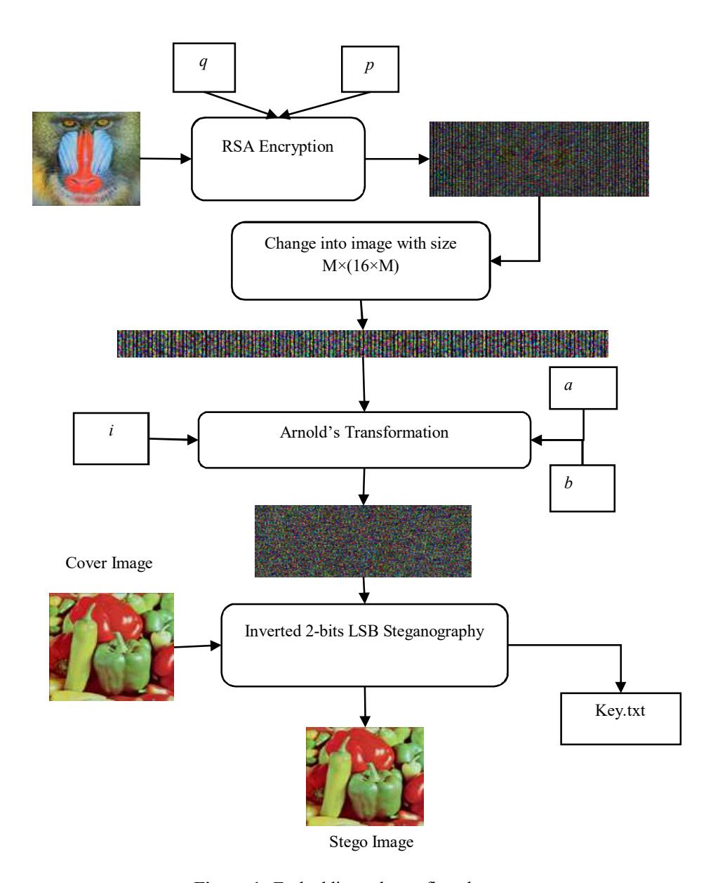
Figure 1 Embedding scheme flowchart.
Figure 1 shows the flow of the embedding process that produces the stego image and the key.txt file.
3.2 Extracting Scheme
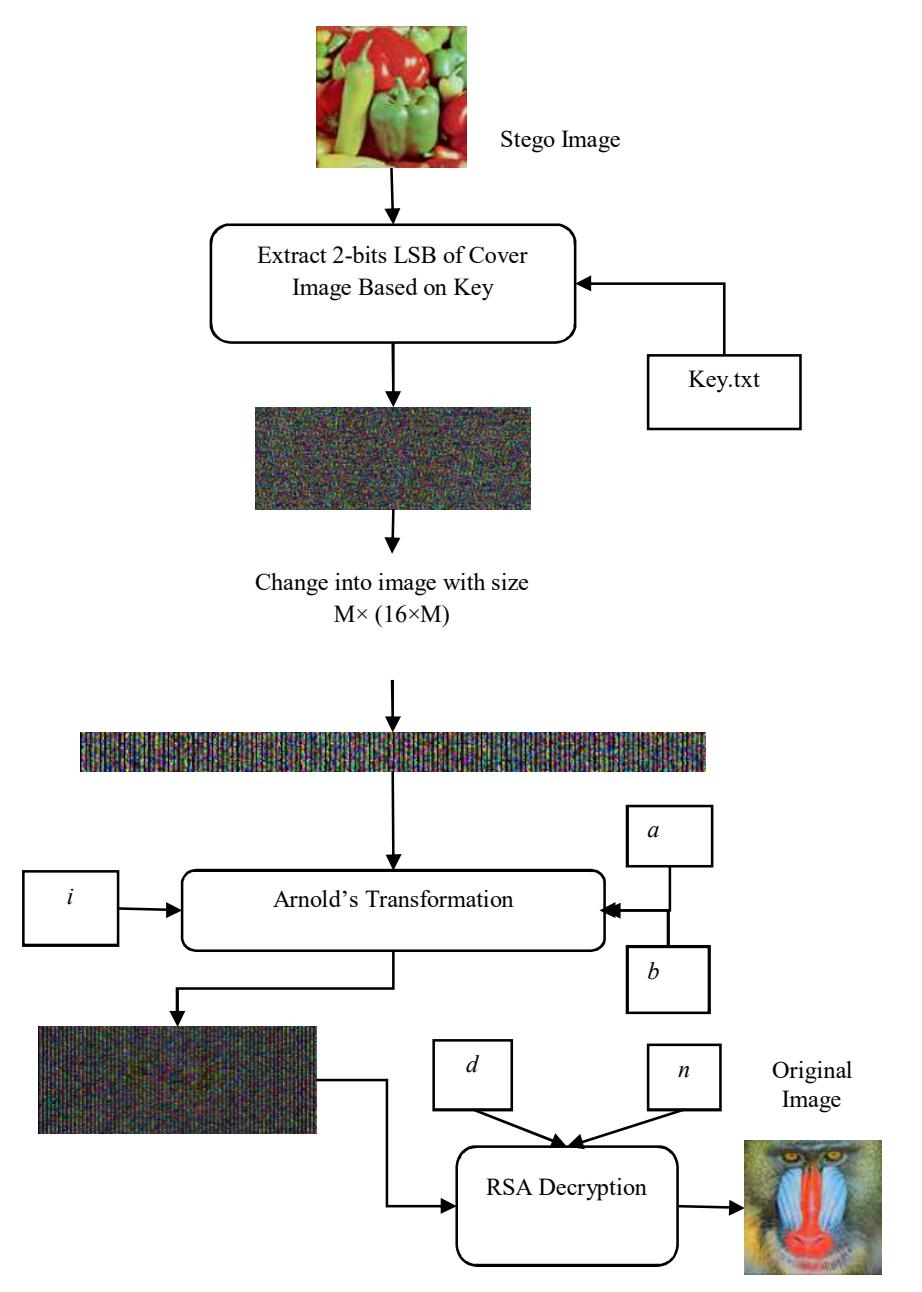
Figure 2 Extracting scheme flowchart.
A flowchart of the extracting scheme is shown in Figure 2. This scheme will produce the original image.
The detailed steps for extracting the secret image are:
- 1. Input the stego image and key.txt. Based on key.txt, which contains the tags from Table 3, extract the message bits.
- 2. Reconstruct the message bits into an image with size \(M \times (16 \times M)\).
- 3. Input values for a, b, and i as parameters to perform the decryption process of Arnold's transformation using Equation 2.
- 4. Divide the result from the previous step into 16 bits per pixel, then convert into a decimal value.
- 5. Input the private key for the decryption process.
- 6. Do RSA decryption for each pixel using the key that has been inputted.
- 7. Rearrange the decryption result into an \(M \times M\) image, i.e. the original image.
4 Result and Testing
Four different images (two color images with size \(64 \times 64\) and two grayscale images with size \(128 \times 128\)) were used as secret messages. They were encrypted and embedded using the proposed scheme. Actually, the size of the image can also be a different size, as long as each side has a size of \(2^n\) pixels and the length of the image is greater than or equal to the width of the image. The reason why this study used square images is that the comparison method [11] can only be implemented with square images. After the encryption process, the encryption result is embedded in a cover image with size \(512 \times 512\).
Figure 3 Secret images: two-color images (a, c) and two-grayscale images (b, d).
Figure 3 shows the secret images that were encrypted using the proposed scheme. The RSA parameters used were p = 1213, and q = 53. Based on these parameters, the pair of keys can be obtained, i.e. the encryption key (e, n) = (503, 64289) and the decryption key (d, n) = (3383, 64289).
Figure 4 Lena.tiff after encryption using RSA.
Figure 4 is lena.tiff, which was encrypted using the key from RSA. After RSA encryption, this cipher image was expanded into binary form. The expansion process converts each pixel in each layer into 8-bit binary and then reconstructs this binary form into an image with size 64 × 1024.
Figure 5 Binary image in each layer.
These three binary (2-bit) images, shown in Figure 5, were merged into one image. The result of the merging process is a color image because each binary image represents a color layer.
Figure 6 Result of the merging process.
Next, the image in Figure 6 was randomized using ACM. The parameters used in ACM were a = 13, b = 31, and i = 7. Because ACM can only be implemented on square images, each 64 × 64 block of the binary image was scrambled, so it was processed in 16 iterations.
Figure 7 Image result after ACM encryption.
The result of ACM encryption is shown in Figure 7. After this process, the result is constructed into an 8-bit image.
Figure 8 Final cipher image of lena.tiff.
The result of the proposed encryption is an M × 2M cipher image, as shown in Figure 8, where M is the actual size of the secret image. Doubling the image size can prevent this encrypted image from statistical method attacks and correlation analysis. The results of the proposed encryption process applied to the four secret images are displayed in Figure 9.
As shown in Figure 10, the histograms of each layer of one of the encrypted images (baboon.bmp) are significantly different compared to that of the original image. The histogram result of the proposed encryption scheme has a flat pattern, which decreases the possibility of being attacked using a statistical method. Compared to the method from [11], the entropy value of the proposed method is higher.
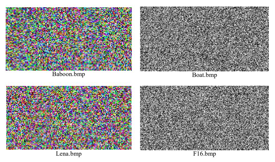
Figure 9 Results of the encryption process using the proposed scheme.
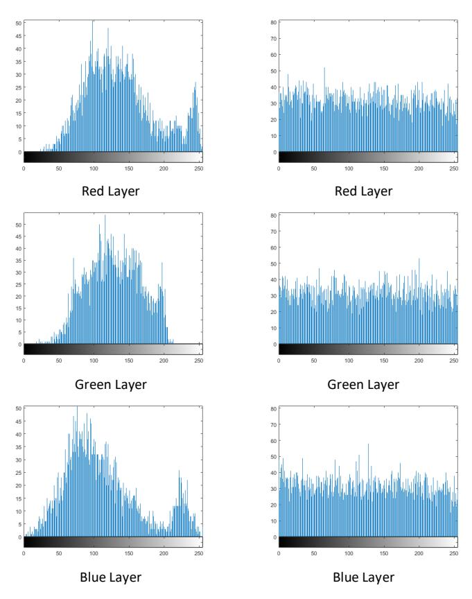
Figure 10 Histogram of the original secret image (left) and histogram of the encrypted image (right).
Entropy is a parameter that shows the variation of the gray level values of an image. The higher the entropy value, the more variation in the gray level of the image.
\[Entropy = \sum_{i} P_i \log_2 P_i \tag{5}\]
From Eq. (5) we can calculate the entropy of each of the four cipher images. \(P_i\) is the probability of two different adjacent pixels. Below are the results of the entropy calculation for the images:
Table 4 Execution time comparison.
| Image Name | Size | Saha et al. [11] (seconds) | Proposed Scheme (seconds) |
|---|---|---|---|
| baboon.tiff | 64 × 64 | 1.4323 | 4.0665 |
| lena.tiff | \(64 \times 64\) | 1.3981 | 4.1995 |
| boat.tiff | \(128 \times 128\) | 2.5874 | 8.1846 |
| F16.tiff | \(128 \times 128\) | 2.7856 | 8.6370 |
f16.tiff
\(128 \times 128\)
6.9761
From Table 4 it can be seen that our method needs more time to be executed. This is because in our method, the ACM process takes 16 iterations to process each block of the binary image.
| Image Name | Size | ACM | Double-size RSA | Saha, et al. [11] | Proposed Scheme |
|---|---|---|---|---|---|
| Baboon.tiff | 64 × 64 | 7.5703 | 7.4034 | 7.4034 | 7.9948 |
| Lena.tiff | \(64 \times 64\) | 7.6990 | 7.4210 | 7.4210 | 7.9936 |
| Boat.tiff | \(128 \times 128\) | 7.1336 | 7.1313 | 7.1313 | 7.9899 |
7.0829
Table 5 Comparison table of entropy value.
A comparison of the entropy values of the proposed method and other methods is shown in Table 5. Double-size RSA and the method proposed by Saha et al. have the same entropy value, even though the latter combines double RSA and ACM. This is because the implementation of ACM only scrambles the image pixels and does not change the pixel values of the image. Thus, the entropy value does not change. The result shows that our method has a better entropy value compared to the other techniques, where the result is equal to 7.9948 for baboon.tiff. The reason why our method generates a high entropy value even though it incorporates ACM is because we implement ACM on the binary form (Figures 6 and 7). Applying ACM in binary form affects the values of the pixels, therefore the entropy value changes. After the encryption process, the result is embedded into a cover image, as shown below. Here, we used two images as cover image.
7.0829
7.9948
Figure 11 Cover images (color image (peppers.tiff) and grayscale image (elaine.tiff).
The encrypted images shown in Figure 9 were embedded in the cover images in Figure 11. These cover images have the same size, i.e. \(512 \times 512\). In the colored cover image, we inserted the secret image into the blue layer, because human vision is less sensitive to the color blue.
Actually, with a size of cover images equal to \(512 \times 512\), the maximum payload that can be inserted using conventional LSB and the methods from [19] and [5] is only 262,144 bits. Meanwhile, the proposed method can provide twice the capacity compared to the previous methods. This is because each pixel in our method can accommodate two message bits while each pixel in the previous methods can only contain one message bit. Therefore, our method provides twice the payload of the previous methods.
| • | 1 0 | ||
|---|---|---|---|
| Cipher | Size Before | Size After | Cipher Size |
| Image | Encryption | Encryption | in Bits |
| baboon.tiff | 64 × 64 | 64 × 128 | 196608 |
| lena.tiff | \(64 \times 64\) | \(64 \times 128\) | 196608 |
| boat.tiff | \(128 \times 128\) | \(128 \times 256\) | 262144 |
| f16.tiff | \(128 \times 128\) | \(128 \times 256\) | 262144 |
Table 6 Payload of cipher images.
Table 6 shows the payload of each cipher image. The size of the cipher images is different after the encryption process. For example, the actual size of baboon.tiff is \(64\times64\) and becomes \(64\times128\) after the encryption process. Then, the cipher image will be inserted into the cover image.
Figure 12 Stego images (a. peppers.tiff and b. elaine.tiff).
As shown in Figure 12, after the insertion process, the stego images cannot be distinguished from the cover image. This means our proposed scheme has a stego image of good quality. The results of the embedding process were tested using mean square error (MSE) and peak signal to noise ratio (PSNR) to prove the quality of stego image.
\[MSE = \frac{1}{M \times N} \sum_{x=1}^{X} \sum_{y=1}^{Y} \sum_{z=1}^{Z} ||C_i(x, y, z) - S_i(x, y, z)||^2\] (6)
where \(M \times N\) is the size of the images, \(C_i\) is the cover image, \(S_i\) is the stego image, and x,y,z stand for the width, height, and layer of the image.
\[PSNR = 10 \log_{10} \frac{2^8 - 1}{MSE} \tag{7}\]
From Eqs. (6) and (7) above we can calculate the values of PSNR and MSE. From [20], good-quality stego images will be achieved if the value of PSNR is above 40 dB. The results of the calculation are as follows:
| Cover Images | Conventional LSB | Proposed Method | |||
|---|---|---|---|---|---|
| Cipher Images | PSNR | MSE | PSNR | MSE | |
| Boat.tiff | 51.1470 | 0.4993 | Inf | 0 | |
| F16.tiff | 51.1325 | 0.5010 | Inf | 0 | |
| Elaine.tiff | Baboon.tiff | 52.3912 | 0.3749 | Inf | 0 |
| Lena.tiff | 52.3889 | 0.3751 | Inf | 0 | |
| Boat.tiff | 51.1417 | 0.4999 | Inf | 0 | |
| Peppers.tiff | F16.tiff | 51.1493 | 0.4991 | Inf | 0 |
| Baboon.tiff | 52.4207 | 0.3724 | Inf | 0 | |
| Lena.tiff | 52.3936 | 0.3747 | Inf | 0 | |
Table 7 Comparison table of PSNR and MSE values.
In the method from [19], to determine the inverted bit, a scheme is used whereby if the number of changed bits is greater than the number of unchanged bits, then the changed bits will be inverted. In other words, if the percentage of changed bits is over 50% then these will be inverted. We tried to apply this scheme to our method. The results were compared to conventional LSB, as shown in Table 7. It can be seen that most of our experiments had infinity value for PSNR, which means that our method did not change the cover image even though messages were inserted. Then, our method was compared to the methods from [19] and [5], as shown in Table 8.
Table 8 Comparison table of PSNR and MSE with previous methods.
| Cover | Cipher | Method of Akhtar, et al. [19] | Method of Bhardwaj, et al.[5] | Proposed Method | ||||
|---|---|---|---|---|---|---|---|---|
| Images | Images | PSNR | MSE | PSNR | MSE | PSNR | MSE | |
| Elaine.tiff | Boat.tiff | 51.1470 | 0.4993 | Inf | 0 | Inf | 0 | |
| F16.tiff | 57.2000 | 0.1239 | 52.4025 | 0.3740 | Inf | 0 | ||
| Baboon.tiff | 55.2997 | 0.1919 | 55.5256 | 0.1822 | Inf | 0 | ||
| Lena.tiff | 55.5270 | 0.1821 | 55.3089 | 0.1915 | Inf | 0 | ||
| Peppers.tiff | Boat.tiff | 57.1690 | 0.1248 | 61.9576 | 0.0414 | Inf | 0 | |
| F16.tiff | 57.2132 | 0.1235 | 61.8370 | 0.0409 | Inf | 0 | ||
| Baboon.tiff | 57.1919 | 0.1241 | Inf | 0 | Inf | 0 | ||
| Lena.tiff | 60.1336 | 0.0631 | 60.2387 | 0.0615 | Inf | 0 | ||
Because the proposed method achieves infinity value for PSNR at a minimum percentage of 50%, we tried to increase the range of percentages of the inverted bits into 74.0-75.0%, of which the result is shown in Figure 15. At this percentage range, the PSNR value of the previous methods decreased. Actually, this happened because the number of changed bits of the previous methods cannot fulfill the minimum percentages of the number of inverted bits, so the previous methods, especially the one proposed by Akhtar, et al. [19], produced similar PSNR values as conventional LSB, as shown in Tables 7 and 8. In the proposed method, the percentages of changed bits denoting the inverted bits can be set depending on need. The factor that affects the percentage is the size of the secret message. If the secret message is large, then the number of bits that change also increases. It also increases the minimum percentages of the number of inverted bits.
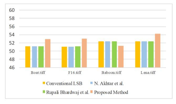
Figure 13 Comparison graph of PSNR with elaine.tiff used as cover image.
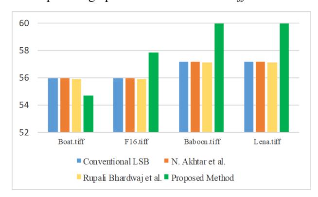
Figure 14 Comparison graph of PSNR with peppers.tiff used as cover image.
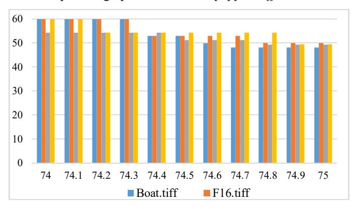
Figure 15 PSNR (dB) value for each percentage in the range of 74.0-75.0%.
5 Conclusion
In this paper, a combined encryption and concealment method is proposed. Its encryption scheme, using a combination of Arnold's transformation and RSA at the bit level, produced encrypted images with better quality than previous methods, with a best entropy value of 7.9948, and generated an unpredictable histogram. Meanwhile, the concealment scheme, using inverted 2-bit LSB modified from classic inverted LSB, produced stego images of good quality. This was proved by most of the PSNR values for each stego image being higher than 40 dB. Moreover, other than the previous methods, the proposed method generated infinity value for PSNR. This means that the proposed method did not change the cover image even though secret messages had been inserted. The concealment scheme showed that the percentages where the PSNR value started to change were in the range of 74.0 to 75.0%. In the middle of this range, i.e. 74.5%, the best PSNR value was generated (equal to 57.8493 dB) with an MSE value equal to 0.1067. In a future work, inverted 2-bit LSB will be used to insert messages into the edge area to improve the imperceptibility value. Furthermore, more bits will be used as bit combination, for example 3 bits, which provides 8 different patterns. These patterns can improve the possibility of higher PSNR values.