
1 Introduction
Driver distraction has been noticed as one of the major causes of automotive crashes and as such is a serious threat to road safety. In the United States, in 16% of all crashes reported, driver distraction was the main cause, where 3,154 people were killed and 424,000 injured (NHTSA, 2013 [1]). As per a recent national survey conducted by TNS India Pvt. Ltd. [2] (2017) for the SaveLIFE foundation, in India 20% of the population have had a near miss or a crash due to the usage of mobile phones while driving. The primary reason behind driver distraction is usage of devices such as mobile phones for listening to music and looking at maps, etc. To address this issue, touchless hand gesture based
Received December 4th, 2017, 1st Revision May 24th, 2018, 2nd Revision August 18th, 2018, Accepted for publication August 31st, 2018.
Copyright © 2018 Published by ITB Journal Publisher, ISSN: 2337-5787, DOI: 10.5614/itbj.ict.res.appl.2018.12.2.4
systems are considered safer as user interface (Loehmann, et al. [3]). The main challenge when developing a vision-based touchless hand gesture detection system is to distinguish gestures with high accuracy in uneven illumination conditions and generalization across users, as discussed by Loehmann, et al. in [3]. To meet these requirements, the proposed method gives flexibility to decide a comfortable region where hand gestures can be easily performed while driving, as shown in Figure 1(a) and (b).
Figure 1 (a) Selection of camera and ROI position (Ohn-Bar, et al. [4]), (b) ROI in Indian scenario, (c) simple flowchart of workflow.
Figure 1(a) shows position of the camera mounted above the driver's seat, which is focused on a small region of interest (ROI) on the dashboard near the steering wheel (Ohn-Bar, et al. [4]). Figure 1(b) shows the ROI setup in the Indian scenario with the steering wheel on the right and the user interface on the left. This system is structured as displayed in Figure 1(c), involving suitable dynamic hand gestures being continuously captured by an RGB camera. The captured gestures are then converted into a gray level image for pre-processing, followed by filtering and feature extraction. Based on two extracted features, shape and motion, the hand gestures are classified. The associated commands control the functionalities of a music player in an interfaced smart phone using an Android application.
The rest of this paper is organized as follows. Section 2 gives details related to our literature review. Section 3 discusses the proposed methodology. Section 4 shows the results of prototype implementation on hardware. Section 5 presents the results and discussion and Section 6 concludes the paper by discussing the future scope of this work.
2 Related Works
Hand gesture recognition for gaming and sign language detection is a recent research area. Study-based research surveys performed by Loehmann, et al. [3] and Parada-Loira, et al. [5] outline touchless hand gestures as a valuable
alternative HMI for in-car systems. Ohn-Bar, et al. [4] developed a vision-based system that uses combined RGB and depth input data to classify hand gestures using the histogram of gradient features and a support vector machine classifier. Ding, et al. [6] proposed an automatic feature extraction method to distinguish similar gestures from 10 numbers and 26 letters with limited accuracy. Kaur, et al. [7] proposed a similar hand gesture based system using an artificial neural network but with static gestures. John, et al. [8] proposed a long-term recurrent convolution network (LR-CNN) algorithm to classify dynamic hand gestures, which was validated on a dataset from the Cambridge Hand Gesture Database. In their approach, the use of multiple frames in a novel tiled image pattern increased the real time computational complexity.
Ketut, et al. [9] proposed an algorithm to reproduce a Balinese papyrus manuscript under uneven illumination using homomorphic filtering with Otsu (global) binarization, while Firdousi, et al. [10] proposed a local adaptive thresholding technique for binarization under non-uniform illumination conditions. Hartanto, et al. [11] proposed a color based segmentation method to recognize static gestures using convexity defects of a convex hull feature extraction method. Tofighi, et al. [12] proposed a method to find the orientation and direction of fingertips based on the distance between the fingertips and the center of gravity.
In India, related works have been proposed by Shirley, et al. [13] for a virtual hand gesture based control system using a Raspberry Pi circuit board. They used different color markers on each finger for gesture recognition. The segmentation classification algorithms were selected based on the coordinates of the color markers instead of skin tone. Similarly Shangeetha, et al. [14] and Singh, et al. [15] have proposed hand gesture detection methods using color based segmentation and a wearable for Indian sign language recognition. Wearables and color markers are not recommended in the automotive domain, considering the driver's comfort. Other works related to vision based solutions either used static gestures or depth parameters and complex algorithms to obtain acceptable accuracy for dynamic gestures. This increases the computational complexity and requires expensive components. Obtaining acceptable accuracy under non-uniform illumination conditions for dynamic gestures using a simple and affordable system remains a challenge.
To overcome these limitations, we propose the following approach: (i) barehand dynamic gesture recognition is used, avoiding the use of a wearable or color markers; (ii) color-based segmentation is not considered, which makes the system independent of skin and background color and hence can be generalized for users; (iii) homomorphic filter with adaptive thresholding is used for edgebased segmentation to develop a system that is robust under different
illumination conditions, while morphological operations like closing, iterative dilation and erosion are used for edge linking to minimize the illumination effect; (iv) open-source software applications (Python and OpenCV) are used for the algorithm development. A prototype was implemented using a low-cost Raspberry Pi 3 and an RGB camera, which makes this system less costly compared to other advanced driver assistance systems.
3 Methodology
The steps followed in the implementation of this work were: (1) selection of suitable hand gestures and dataset collection; (2) image pre-processing; (3) shape and motion feature extraction; (4) gesture recognition.
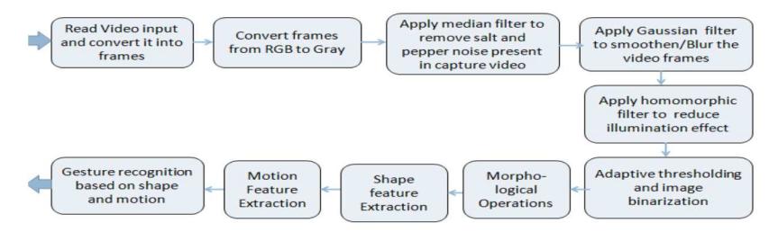
Figure 2 Block diagram of methodology used in this work.
3.1 Selection of Suitable Hand Gestures
Three easy-to-perform dynamic hand gestures were selected from the Cambridge Hand Gesture Database. As per John, et al. [8], this database contains RGB videos of 9 classes captured in 5 sets of non-uniform illumination conditions (Figure 4), which has 100 video samples per class. Figure 3 shows some frames from the selected hand gestures and the commands associated with them.
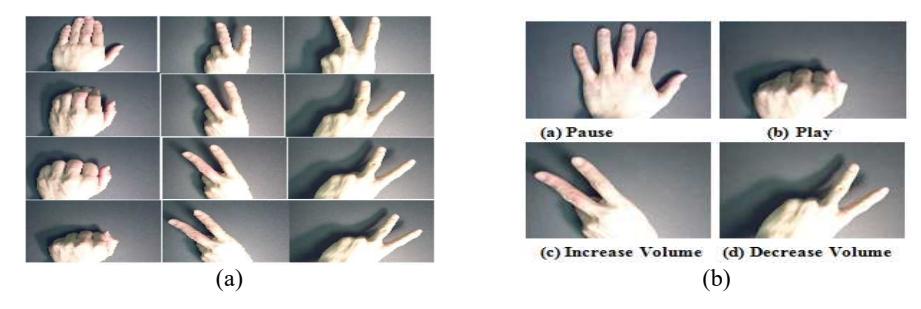
Figure 3 Three selected hand gestures from Cambridge public dataset: (a) column-wise: gesture numbers 0002, 0006, and 0007, (b) gestures with associated commands (John, et al. [8]).
3.2 Image Pre-Processing
Figure 4 shows some globally binarized frames (using the Otsu method) of selected gestures from the Cambridge Hand Gesture Database without applying pre-processing. As these images are corrupted by non-uniform illumination and noise, deteriorating the performance of vision-based systems, it is necessary to perform image preprocessing before segmentation to reduce noise and illumination effects.
Figure 4 Five image sets showing uneven illumination and direction of illumination from the Cambridge Hand Gesture Database and their globally binarized result without preprocessing. Source of illumination: (a) down, (b) right-down, (c) right-up, (d) left-up, (e) right-down.
In the proposed method, a Gaussian filter, G(x,y), is used for image smoothing, blurring the image by reducing small details and noise. A 5×5 Gaussian mask is used after selecting standard deviation \(\sigma\) as 2 for this work (Gonzalez, et. al [16]).
\[G(x,y) = \frac{1}{2\pi\sigma^2} e^{-\frac{x^2 + y^2}{2\sigma^2}}\] (1)
After removing the noise, homomorphic filtering is used to suppress uneven illumination by dynamic compression and image enhancement. The nomenclature is as per Reference [9]. Any image f(x,y) is considered as a combination of illuminance i(x,y) and reflectance r(x,y) components, which represent low and high frequencies respectively.
\[f(x,y) = i(x,y) * r(x,y)\] (2)
By taking the log of Eq. (2), the illuminance and reflectance can be separated.
\[ln(f(x,y)) = ln(i(x,y)) + ln(r(x,y))\] (3)
Fast Fourier transform is used to convert Eq. (3) into the frequency domain.
\[fft(ln(f(x,y))) = fft(ln(i(x,y))) + fft(ln(r(x,y)))\]
\[Z(u,v) = Fi(u,v) + Fr(u,v)\]
(4)
The Butterworth high-pass filter is defined as H(u,v), given in Eq. (5) as follows:
\[H(u,v) = (\gamma H - \gamma L)(1/1 + (D0/D(u,v))2n) + \gamma L \tag{5}\]
In the above equation, D0 is taken as the cut-off frequency, n is the order of the Butterworth filter and D(u,v) is the distance between a point (u,v) and the center of the frequency rectangle (Gonzalez, et. al [16]). The illumination condition is suppressed by selecting \(\gamma_H\) and \(\gamma_L\) as 1.1 and 0.4, respectively. After multiplying H(u,v) with the frequency domain components, the illumination effect is suppressed.
\[Z(u,v) * H(u,v) = Fi(u,v) * H(u,v) + Fr(u,v) * H(u,v)\] (6)
Then, to obtain the image from the frequency components, the inverse Fast Fourier transform is taken in Eq. (7):
\[ifft[Z(u,v)*H(u,v)] = ifft[Fi(u,v)*H(u,v)] + ifft[Fr(u,v)*H(u,v)]\] \[(7)\]
Which becomes
\[s(x,y) = i'(x,y) + r'(x,y)\] (8)
To reverse the process of taking the log in Eq. (9), the exponential is taken from Eq. (8).
\[exp(s(x,y)) = exp(i'(x,y)) + exp(r'(x,y))\](9)
Thus, \(f_o(x, y)\) is the enhanced image as per the following Eq. (10):
\[fo(x,y) = io(x,y) * ro(x,y)\] (10)
After homomorphic filtering, 'salt and pepper' noise is filtered by median filter followed by adaptive thresholding for edge-based segmentation instead of global thresholding to deal with uneven illumination and noise.
Figure 5 Sample result of a gesture frame from Set 5 (see Figure 4) at different stages of preprocessing.
3.3 Shape and Motion Feature Extraction
3.3.1 Shape Feature Extraction
After preprocessing and binarization, the iterative closing operation is used to link the broken edges. Then, the contour with maximum area and its convex hull are obtained for each frame. By calculating the convexity defects between the fingers of the hand gesture using the cosine rule, the defect count is obtained (Tofighi, et al. [12]). The cosine rule for triangles is applied to find the angle of defect between the contour and the convex hull. If an acute angle is found, the finger count is increased by one.
3.3.2 Motion Feature Extraction
Once the contour with maximum area has been found for each frame, the direction of motion is extracted from the gesture video by following the trajectory of the center of the contour in between frames. Then, by comparing it with a threshold value, the hand movement direction is detected as 'up', 'down', 'left', 'right' and combinations thereof (Hariyono, et al. [17]).
3.4 Gesture Classification Algorithm and Associated Commands
Based on the two features shape and motion, the finger count and the direction of motion are extracted. Then, a condition-based (if/else) classification algorithm is used to identify the gestures. Gesture 1 has 5 fingers and the direction of motion is 'down'. Gestures 2 and 3 have 2 fingers and their directions of motion are 'right' and 'left' respectively. The associated commands are palm/'pause' and punch/'play'. Two fingers with right and left motion decrease and increase the volume respectively.
4 Prototype Implementation
A prototype of this work was implemented on a Raspberry Pi 3 hardware unit using a USB charger, monitor, mouse and keyboard. A micro SD card with Python 3.5 and OpenCV 3.1.0 installed was used for algorithm development. It received continuous hand gesture input from the IP webcam of an Android phone connected to the same local network (via hotspot/tethering) as Raspberry Pi.
The hand gestures were performed against a static background. Once the gesture was recognized, the output was displayed and the associated command was sent to the interfacing Android application, called GestureMusic. This application can control the functionalities (pause, play, increase volume, decrease volume)
of the default music player in the same Android phone, as explained in Sections 4.1 and 4.2.
4.1 Android Application (GestureMusic)
An Android application called GestureMusic was developed using Android Studio to control the functionalities of the music player via received commands. Figure 6 shows the layout of the Android application, containing 5 buttons named after their functionality. System integration is discussed in Section 4.2.
Figure 6 Layout of Android application GestureMusic.
The default command 'open' opens the default music player on the Android phone. If the received command is 'play' then it plays the current song, if it is 'pause' then it pauses the song. 'Increase volume' and 'decrease volume' increase and decrease the volume respectively. In case of random gestures, no action is taken.
4.2 System Integration
In this approach, the processor is connected via a hotspot/tethering to the Android smart phone with the music player as shown in Figure 7. The developed algorithm recognizes hand gestures and updates the associated commands in a file (command.txt), which is continuously read by the host network. Once the host server starts, a command is received at the client server, which reads the file at continuous intervals and controls the functionalities of the music player accordingly. The interval of reading commands from the host server can be decreased up to a maximum latency of 5 milliseconds depending on the criticality of the application.
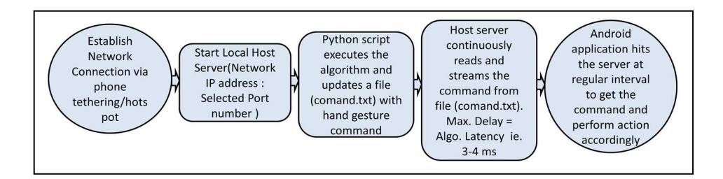
Figure 7 Interfacing hardware unit with Android using local networking.
5 Results and Discussion
Based on the described methodology, the selected gestures from the Cambridge Hand Gesture Database are recognized and the associated commands are sent to the Android application. Figure 8 shows sample results of gesture frames with finger count, direction of motion, and the associated commands displayed on the top right corner of the frame. At the bottom, dx and dy show the change in the centroid of the contour in the X- and Y-direction respectively. Based on these two values, the direction of motion is determined. To validate the method, a prototype was implemented, as described in Section 4. It is evident from the results (Figures 8 and 9) that the proposed algorithm worked equally well on both datasets (Cambridge dataset and real-time gestures integrated with Android IP webcam). The prototype was tested under non-uniform illumination captured against different background colors in a laboratory setup, as shown in Table 1 and Figure 9.
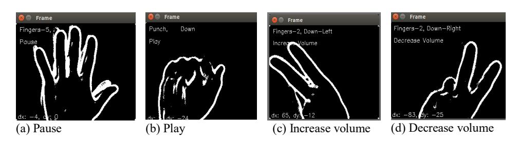
Figure 8 Sample results for offline standard dataset (Cambridge hand gesture dataset).
| Rows | Details of illumination | Users |
|---|---|---|
| Row 1 | Top-right illumination source | User 1 |
| Row 2 | Top-left illumination source | User 2 |
| Row 3 | Different colored backgrounds with shadow | User 2 |
| Row 4 | Different colored backgrounds under minimal illumination | User 2 |
Table 1 Description of gestures shown in Figure 9.
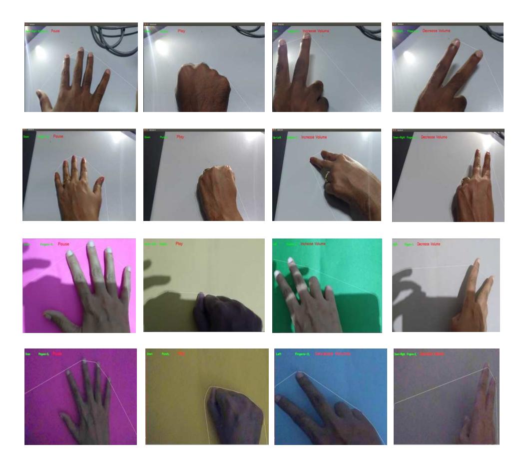
Figure 9 Sample results of prototype implementation for online real-time gestures.
5.1 Performance Evaluation of Proposed Method on Cambridge Hand Gesture Dataset for Selected Gestures
The Cambridge Hand Gesture Database provides gestures performed in five different non-uniform illumination conditions. Each type of gesture has 20 video samples available under all five different sets (Sets 1 to 5, as shown in Figure 4). Thus, each type of gesture in the selected dataset has a total of 100 video samples per class. As the number of frames per video is not constant in the dataset, each output frame was considered while evaluating overall system accuracy as per Eq. (11).
Algorithm latency was calculated using a system timer, which is the time taken by the system to run the algorithm, i.e. the delay between input and obtained output.
| Table 2 | Frame-by | y-frame accurac | v calculation | for selected | dataset. |
|---|
| Average accuracy calculated frame by frame for each gesture | Total | ||||
|---|---|---|---|---|---|
| Illumination sets | Number of videos | Gesture 1 (pause/play) | Gesture 2 (decrease volume) | Gesture 3 (increase volume) | average accuracy |
| Set 1 | 20 | 72.65% | 88.63% | 95.28% | |
| Set 2 | 20 | 60.09% | 62.41% | 84.82% | 81.38% |
| Set 3 | 20 | 70.28% | 74.04% | 92.94% | |
| Set 4 | 20 | 71.86% | 83.69% | 98.65% | |
| Set 5 | 20 | 74.63% | 93.47% | 97.26% | |
| Total | 100 | 69.90% | 80.45% | 93.79% | |
Table 3 Overall system accuracy calculation for selected dataset.
| Confusion Matrix | ||||
|---|---|---|---|---|
| Class 1 | Class 2 | Class 3 | Total Nu | ımber of Videos |
| 79 | 8 | 13 | 100 | |
| 4 | 96 | 0 | 100 | |
| 2 | 0 | 98 | 100 | |
| Parameters | - | |||
| Accuracy | 91% | - | ||
| Precision | 91% | |||
| Recall | 90.4% | |||
\[Accuracy = \frac{True Positives}{Total Images}\] (11)
\[Precision = \frac{True Positives}{(True Positive+False Positive)}\] (12)
\[Recall = \frac{True Positives}{(True Positive+False Negative)}\] (13)
True positive (TP) – actual class of gestures predicted as the same class gestures False negative (FN) – other class of gestures predicted as labeled class gesture False positive (FP) – labeled class gesture but predicted as other class gesture
Total TP = 79 + 96 + 98 = 273 Total FN = 8 + 8 + 13 = 29
Total FP = 21 + 4 + 2 = 27
| Latency cale | A | ||||
|---|---|---|---|---|---|
| Illumination sets | Number of videos | Gesture 1 (pause/play) | Gesture 2 (decrease volume) | Gesture 3 (increase volume) | Average system latency (ms) |
| Set1 | 20 | 3.64213 | 3.96 | 4.1324 | |
| Set2 | 20 | 3.581369 | 4.0736 | 4.1 | 3.78567 |
| Set3 | 20 | 3.522038 | 4.0736 | 3.52 | |
| Set4 | 20 | 3.726912 | 3.646 | 3.52 | |
| Set5 | 20 | 4.039061 | 3.727889 | 3.52 | |
| Total | 100 | 3.702302 | 3.896218 | 3.75848 | |
Table 4 Overall system latency calculation for selected cambridge gestures dataset
An overall system accuracy of 91% and a frame-by-frame average accuracy of 81.38% were achieved, as shown in Tables 2 and 3, and a system latency of 3-4 ms was achieved as can be seen from Table 4. The overall system accuracy and latency obtained give a satisfactory performance to control non-critical automotive applications, such as a music player or other in-car infotainment systems.
5.2 Comparative Analysis
A comparative analysis of the proposed algorithm with recent related works for a Cambridge hand gesture dataset captured under non-uniform illumination was performed of which the result is shown in Table 5. The proposed algorithm requires significantly less computational time for a similar average accuracy range, which makes it suitable for real-time implementation.
Table 5 Comparision with recent works for cambridge hand gesture dataset as per John, et al. [8].
| Performance Comparison with Recent Algorithms | ||||
|---|---|---|---|---|
| Algorithm | Accuracy | Algorithm computational time | ||
| Proposed algorithm | 91% | 3-4 ms | ||
| 3 random frames LRCN | \(90.9 \pm 1.1\%\) | 110 ms | ||
| 16-frame LRCN | \[86.5\pm2.7\%\] | 180 ms | ||
6 Conclusions and Future Scope
The proposed system was developed to provide a robust preprocessing algorithm to deal with challenging real-time in-car illumination conditions. Color-based segmentation methods were not considered, which makes this system robust towards different skin colors. Approaches that can lead to driver discomfort were avoided. Homomorphic filtering with adaptive thresholding followed by morphological operations has shown good results in preprocessing the challenging dataset from the Cambridge Hand Gesture Database captured under non-uniform illumination conditions. An overall system accuracy of 91%, an average frame-by-frame accuracy of 81.38%, and a system latency of 3.78 milliseconds per video sequence were achieved for three selected hand gestures from the Cambridge hand gesture dataset. The very low latency of this algorithm makes it suitable for real-time implementation.
The future scope of this work is to enhance its accuracy by implementing advanced machine learning classification algorithms. More gestures can be introduced in the future, to operate more complex interfaces. Infrared sensors can be integrated with this system to recognize gestures in complete darkness.