
1 Introduction
The increasing growth of heterogeneous mobile ad-hoc networks (H-MANET) has opened an innovative horizon in the field of telecommunication. An H-MANET contains mobile nodes with different configurations that are self-configuring to support the communication between one another. Among the different network architecture designs, MANET have drawn a great deal of attention because of issues with energy, security, path discovery, etc. by using different node configurations in the network [1-3].
An appropriate routing scheme is required in conditions when temporary connectivity of the network is needed, for example in battlefields, disaster areas, etc., due to their ability of handling node failure as a result of low energy and fast topology changes [4-6].
They work either proactively or reactively. Devising such routing scheme poses a considerable technological challenge as the devices in the network are battery driven. They must preserve energy in order to maximize battery life. The shortest path is one of the most generally accepted criteria in routing procedures and is recommended by the MANET Working Group [8-12].
One difficulty with this approach related to heterogeneous networks is that some nodes are utilized more frequently, which depletes their batteries faster, causing energy disparity. As a consequence the network may be disconnected from associated networks. Thus, the shortest path is not an appropriate metric for choosing the routing in heterogeneous networks. In this paper, we propose an energy-efficient routing algorithm, which first discovers disjoint paths and then selects the most energy-efficient path, leading to longer battery life. They are derived from one of the major routing methods, Ad-hoc On Demand Distance Vector (AODV).
The remaining part of this paper is structured as follows. Section 2 reviews related work. Section 3 describes the proposed system and its implementation. A performance analysis of the proposed system is discussed in Section 4 and Section 5 concludes the work.
2 Related Works
Several works are related to this research topic:
2.1 Multi-Disjoint-Path-based Routing in MANET
On-demand multipath routing protocols establish many paths between the source and the destination during route discovery [7]. The route discovery procedure is invoked when the existing routing paths do not work any longer or when there are only leftover paths. Multi-disjoint-path-based routing is implemented with the AODV routing protocol [13-15].
2.2 Modified AODV
This approach considers node disjoint when node disjoint routes fail independently. When a source requires a route to a target, the route discovery procedure is started. The discovery procedure usually includes net-wide flooding of route request (RREQ) packets addressing the target, expecting a route reply (RREP).
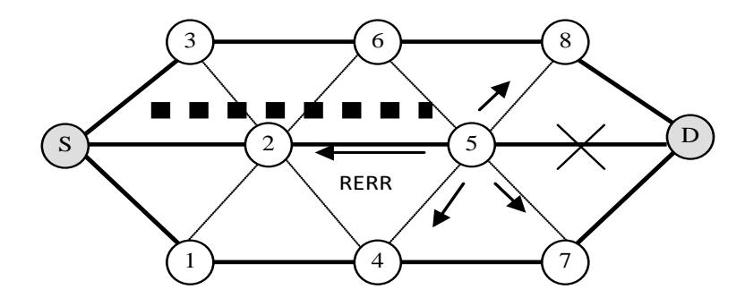
Figure 1 Link [7].
2.2.1 Modification in Route Request
To find out node disjoint paths, the destination must identify all routing paths of every existing route so it can choose the right path among a number of alternative paths. Once the RREQ packets are created and forwarded via the nodes, every node appends the personal address to the RREQ packet. As a node gets a route request packet, it first verifies the path accumulation list at the start of the packet in addition to computing the hop count between the source and itself and identifies the smallest number of hops in its RR table entry.
Consider the example in Figure 2. From node S to c there exist 5 routing paths: . s cs b cs a cs b d cs a c → →→ →→ →→→ →→ ,,, ,
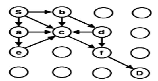
Figure 2 Request handling at nodes [7].
The number of hops is 1, 2, 2, 3, 3 respectively. As soon as node c gets the route request packet for the first time for route s c → , this route identifies 1 as the smallest number of hops in its RR table. When node c gets RREQ duplicates via alternative routes, it determines the hop count and also compares it with the smallest number of hops in its entry in the RR table. Since the number of hops in the list of four routes is always larger than 1, the 4 RREQ duplicate packets are dropped.
2.2.2 Modification in Route Reply
Once a RREQ packet reaches its target, the target is accountable for the nodedisjoint path characteristic. Once the node-disjoint path has been verified, the target creates a RREP packet that includes the node list of the entire route. The intermediary node builds up a forward path entry to the target in the route table along with a reverse path entry to the source in the RR table.
In accordance with the info from the path identifiers (IDs), a forward path entry traces the IP address of the target along with the IP address of its neighbor from which the RREP reported. Actually, the reverse path entry traces the source's IP address as well as the next hop from the source's IP address.
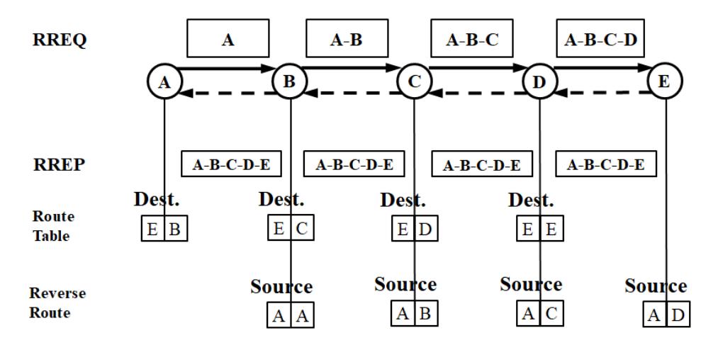
Figure 3 Modified route [7].
2.2.3 Selection of Disjoint Paths
Consider the example in Figure 4. The route request procedure finds the route with the least overhead in the whole network. Source S transmits an RREQ packet. Every intermediary node utilizes the path with the least routing overhead to disseminate and reject packets. Hence, only seven packets with the following route lists will reach the destination, D: 2-5, 3-6-8, 1-4-7, 2-6-8, 2-5- 8, 2-4-7, 2-5-7.
Note that not every packet that reaches the target is node-disjoint. Then, the destination is liable for electing and keeping the record of the multiple nodedisjoint routes. In order to reduce the routing overhead in every node, we restrict the number of node-disjoint routes to 3, even though more could be explored.
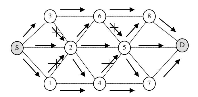
Figure 4 Route request from S to D.
These three RREPs travel through network source S, as already explained in the route reply section. The RREPs reach the source, making entries in the routing tables of each intermediate node and forming three node-disjoint paths, as shown in Figure 5.
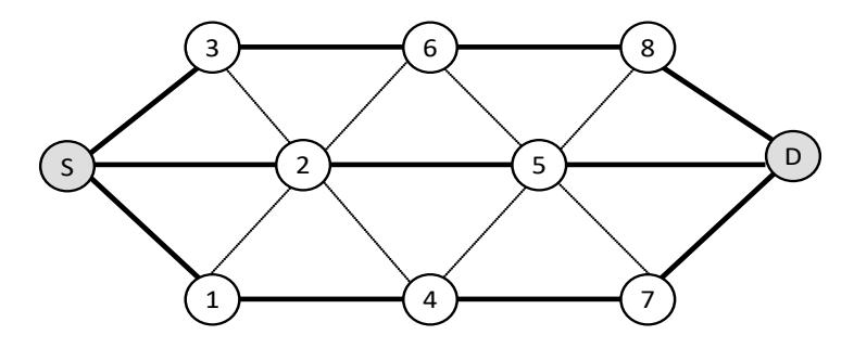
Figure 5 Discovered paths [7].
2.2.4 Enhancement to Improve Performance
Consider when a link breaks. An RERR packet is generated and sent in the network to tell about the failure of the node. Source node S receives the RERR and stops transmission on this route. However, the packets on the way are lost, as shown in Figure 1. Apart from this, when the destination sends its replies, there is a possibility that the nodes involved in the routing list given to the RREP fail. The RREP will be rejected, but the node may have some alternative paths that could be used in case more than one path are not established in the whole process. If we could use these alternate paths, we can have much higher probability of discovering at least one part of the route from the process of finding disjoint paths.
In the proposed method the following features were added:
- 1. Reduce loss of packets on the way in case of link failure.
- 2. Still find paths in case of failure during RREPs.
- 3. New path selection criteria for a destination in case of multiple candidates.
Drawback: Energy consumption is one of the most important concerns in the implementation of ad-hoc networks [16-19]. In this scheme, path selection based on the shortest path in view of shorter battery life is not conducted. Thus, this scheme for solving path breakage is not efficient in terms of energy consumption in the nodes.
3 Proposed System and Implementation
To show the proposed approach at work we look at a scenario with 10 nodes with different energy levels. Figure 6 shows the 10 nodes with their different energy levels. Figure 7 illustrates the route discovery process from the source (S) to the destination (D). This will find the disjoint paths between S and D. Paths that have common nodes are rejected.
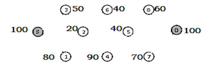
Figure 6 Ten nodes with different energy levels.
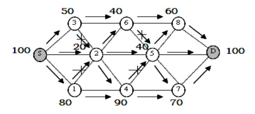
Figure 7 Route discovery.
The disjoint paths have been discovered by the destination and the destination sends the route reply packet shown in Figure 8 along each path. The routing table is updated based on the maximum energy in the reply packet by comparing to the previous one. The route reply packet is then forwarded.

Figure 8 Disjoint route discovery.
Figure 9 shows that the maximum energy path has been selected for transferring the data packets.
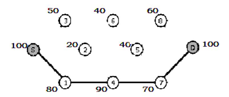
Figure 9 Data transfer through maximum energy path.
Limitation of Modified Approach: In this approach we select the path based on maximum energy so it may or may not be the shortest path and the energy consumed by this path may be greater than that of others.
4 Performance Analysis
The parameters used for evaluating the new routing protocol algorithm were as follows:
- 1. Network Life Time: This is measured on the basis of the number of dead nodes vs time. If the last node's dead time increases then the lifetime of the network increases.
- 2. Packet Delivery Ratio: This is the ratio between received data packets and sent data packets.
- 3. Received Data Packets: This is the number of data packets in the network received by the destination.
- 4. Routing Overhead: This is the overall number of routing packets transmitted at some point in the simulation to set up the path for communication. In ad-hoc networks, the nodes frequently change their position in the network. As a result, some unstable routes are created in the routing table, which leads to unwanted overhead.
The performance was analyzed as depicted in Figures 10-17.
Table 1 Parameters used for analysis.
| Parameter | Value |
|---|---|
| Channel type | Wireless/IEEE 802.11b |
| Platform | Linux (Ubuntu 10.4) |
| NS version | NS-2.34 |
| Number of nodes | 50 wireless node |
| Routing protocol | AODV/Proposed Modified AODV |
| Area size | 1000 m X 1000 m |
| Simulation time | 500 seconds |
| Initial energy | 300,200,100 joule (heterogeneous) |
| Transmission range | 250 m |
| Packet type | Constant bit rate |
| Packet size | 512 bytes |
| Mobility speed | 1/3/5 m/sec |
| Mobility model | Random 1 |
| Pause time | 10/20 seconds |
| Packet arrival time | 0.1 seconds |
| Number of connections | 10/15 |
These parameters were measured against:
1. Different mobility from 1/3/5 m/sec with pause time at 10 sec, number of connections at 10 and the rest of the parameters as given in Table 1.
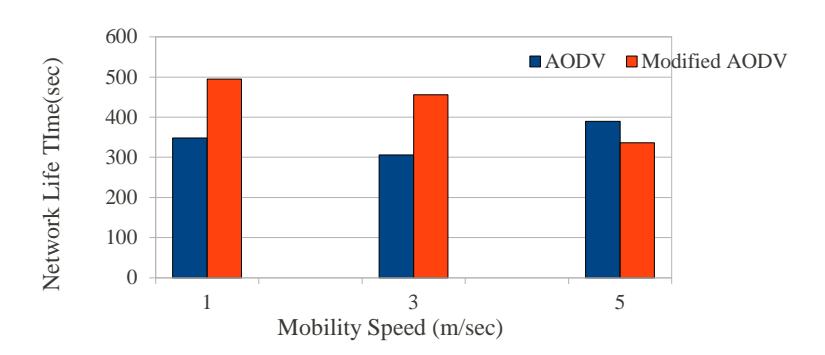
Figure 10 Mobility (m/sec) vs network lifetime with 10 sec pause time for 10 connections.
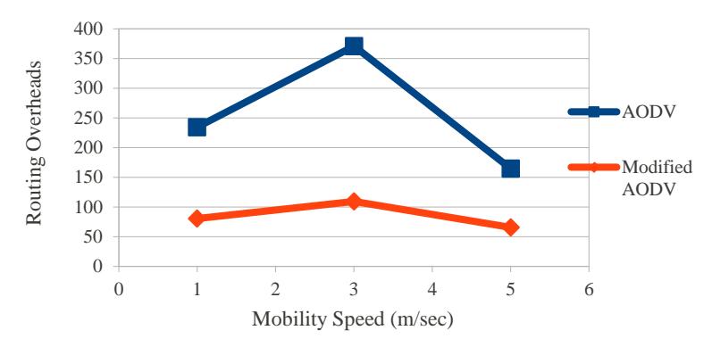
Figure 11 Mobility (m/sec) vs routing overhead with 10 sec pause time for 10 connections.
2. Different mobility from 1/3/5 m/sec with pause time at 10 sec, number of connections at 15 and the rest of the parameters as given in Table 1.
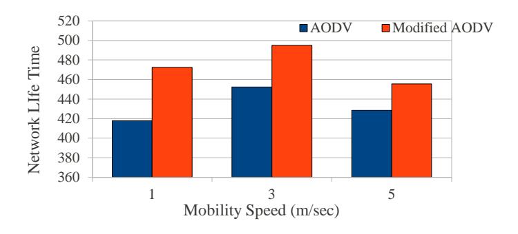
Figure 12 Mobility speed (m/sec) vs network lifetime with pause time at 10 and number of connections at 15.
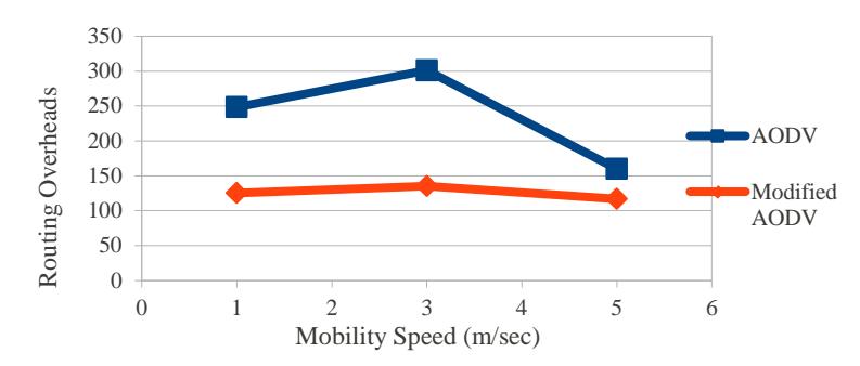
Figure 13 Mobility speed (m/sec) vs routing overhead with pause time at 10 sec and number of connections at 15.
3. Different mobility from 1/3/5 m/sec with pause time at 20 sec, number of connections at the 10 and rest of the parameters as given in Table 1.
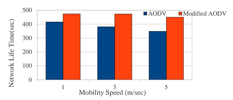
Figure 14 Mobility speed vs network lifetime with pause time at 20 sec and number of connections at 10.
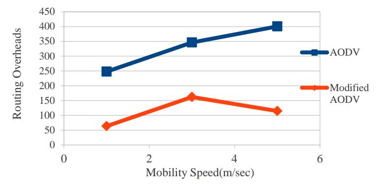
Figure 15 Mobility speed vs routing overhead with pause time at 20 sec and number of connections at 10.
4. Different mobility from 1/3/5 m/sec with pause time at 20 sec, number of connections at 15 and the rest of the parameters as given in Table 1.
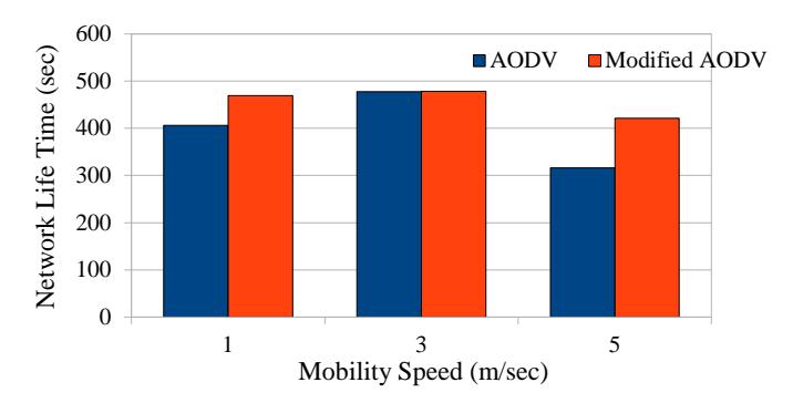
Figure 16 Mobility speed vs network lifetime with pause time at 20 sec and number of connections at 15.
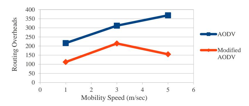
Figure 17 Mobility speed vs routing overhead with pause time at 20 sec and number of connections at 15.
5 Conclusions
The proposed method for selecting the maximum energy path among different paths from the source to the destination reduces the drawback of node breakage because the amount of energy used by the nodes through which communication takes place decreases. This approach increases the lifetime of the network due to which the number of received and sent data packets increases and the routing overhead is reduced because the path is stable.
In the future the number of dropped packets should be reduced in order to increase the PDR and get alternative paths at once when path breakage takes place due to mobility.