
1 Introduction
Handoff, or handover, is an essential process in wireless networks. Active user sessions are maintained during base station switching by the handover mechanism. Efficient handover by a seamless handover algorithm makes the concept of femtocell technology successful. Therefore, it is necessary to examine the technique for cell selection during the handover process in order to reduce unnecessary handovers and to improve the user benefits with regard to gained
Received May \(3^{rd}\), 2020, \(1^{st}\) Revision November \(30^{th}\), 2020, \(2^{nd}\) Revision February \(17^{th}\), 2021, Accepted for publication May \(7^{th}\), 2021.
Copyright © 2021 Published by IRCS-ITB, ISSN: 2337-5787, DOI: 10.5614/itbj.ict.res.appl.2021.15.1.4
capacity. Generally, three stages are distinguished in the process of LTE handover [1]. Collecting handover related information/measurements from the serving and neighboring base stations is the first phase of the handover process; usually this is called the information or measurement gathering phase. The handover decision phase is the second stage, which is responsible for where and when to decide the handover; it should include a cell selection technique. The execution phase is the third stage in the handover process, when the UE disconnects itself from the serving base station (eNB or HeNB) and connects itself to the target [2-6]. The Home-eNB or HeNB (femtocell) model applies a hard handover mechanism, which means that the UE is terminated completely from the serving HeNB/eNB and then connected to the target one. A soft handover, which allows the UE to remain on the serving base station for a while before moving to the target, is not applicable in the femtocell concept [7]. A multi-tier LTE network has three different possible scenarios [8]. Firstly, Inter-HeNB, which occurs when the UE changes its femtocell (HeNB) to another one. Secondly, hand-out, which occurs when the UE changes its femtocell (HeNB) to a macrocell (eNB). Thirdly, hand-in, which occurs when the UE changes its macrocell (eNB) to a femtocell (HeNB).
Figure 1 shows the three possible scenarios mentioned above. Different backhaul routes of HeNB and eNB make the process of the hand-in scenario quite difficult [9]. Moving from HeNB to eNB is almost the same as an eNB-eNB handover; control signaling can be transferred to the core network via a backhaul link because of unavailability of an X2 interface [10]. However, control signaling is delivered between femtocells internally via X2 and S1 interfaces through an HeNB gateway [11-12]. On the other hand, the evolved packet core (EPC) may receive the control traffic if access control is required at the mobility management entity (MME) [7].
Figure 1 Multi-tier handover scenarios.
Several mobility management algorithms have been proposed in [13-17] to predict the target cell. The authors of [13] suggest an effective measurement scheme and network investigation for user equipment mobility from macrocell to femtocell (hand-in/handover scenario). The suggested scheme includes a macrocell arrangement procedure based on location to reduce the number of towers located outside the coverage area. When the UE route is estimated based on prior measurement outcomes, every femtocell that is near to the UE is added to the neighbor macrocell list.
The second part of the proposed procedure is a femtocell-assisted handover decision to ensure that the UE handover is smooth. Nevertheless, in both parts of the procedure, both the macrocells and femtocells are essential to maintain the UE route or identify the uplink index, which is obtained from the UE, based on further network measurements of the macrocells and femtocells. In contrast, in [14] the researchers proposed a self-organizing architecture using a unique wireless scheme to reduce the candidate femtocell list in a dense femtocell scheme. Several handover decision structures based on machine-learning methods were used in [14] and [15] to choose the target cell in the vertical handover stage. The researchers in [15] suggest a novel scheme accompanied by resource allocation to discover the best station using its measurements (bandwidth and power) to boost the system throughput. The suggested structure is performed in a spectrum scenario for non-dense femtocell distributions. In terms of resource utilization, the outputs of the proposed algorithm showed an increase in system throughput.
Furthermore, to decrease the number of needless handovers and the number of handover failures, the authors in [16] proposed ant colony optimization for the handover stage. The proposed scheme uses several input factors along with RSS, such as prediction of traveling distance, UE velocity, cost of service, and bandwidth. Furthermore, the proposed scheme is based on a database that always remains up-to-date by guaranteeing that the UE continuously examines the network's status. Thus, after normalization and initialization of all input factors in each accessible station, the optimal station is chosen using the database. Nevertheless, the cost of updating the mobility database and the calculation time increase accordingly. Furthermore, the researchers in [17] proposed location predication and the mobility history in the handover decision stage to reduce the number of unnecessary handovers. The scheme calculates the required time for the UE to remain on a femtocell to eliminate interim femtocells users. The researchers used the previous procedure of UE mobility along with mobility structures established in advance to predict the connection period for the next femtocell.
A new cell selection technique is proposed to pick the nominated cell depending on the path of the UE by using a reinforcement learning algorithm. Suman's algorithm [18] is used as the benchmark in terms of the control signaling rate and the packet loss ratio. We built our own module in the LTE-Sim simulator to test the network output results. The rest of this article is organized as follows. The Qlearning structure is explained in Section 2. In Section 3 we discuss our suggested procedure. We evaluate our work in terms of control signaling rate and packet loss ratio in Section 4. The conclusion and future work are given in Section 5.
2 Research Method
We customized the selected reinforcement learning algorithm (Q-learning) to serve our technique in finding the best target cell among all neighboring cells, as follows:
1. Environment: this includes the agent and other elements in the network. The environment covers all base stations in the neighboring cell list (NCL), which includes the femtocell HeNBs and macrocell eNBs. It is considered a finitestate, stochastic and discrete-time network.
In this environment we implement Bellman's optimality [19] as a unique agent. Q(s,a) refers to the maximum value for the Q-function that shows the best activity (b) for each potential upcoming pair (υ,b). For every phase in the learning procedure with a learning rate α, the Q-value should be calculated with Algorithm 1:
Algorithm 1. One trail of Q-learning process
s : existing state
a : activity taken depending on the decision selection strategy
R(s,a): reward as an output of activity (a) in state (s)
 : upcoming state after executing an activity (a)
Step 1: set the initial state (s)
Step 2: select an activity (a) depending on decision selection strategy
Step 3: a reward R(s,a) is obtained as a result
Step 4: update
                (, ) = (1 − )−1
                                     (, ) + (
                                                   (, ) +
 −1
            (, ))
Step 5:  ←
- 2. Agent: the activity creator, which includes the eNB user equipment (UEeNB) performing the handover procedure starting from its current station to the surrounding station that offers the best efficiency.
- 3. State: the existing state of the environment, which includes the existing macrocell stations. S is a set of states denoted as S = {s = 1,2,…,NNCL+1}. (s = 1), representing the default state of the user equipment while it is connected to a macrocell. To expedite choosing the best station, we need to shortlist the surrounding stations; to do so we suggest a Q-learning scheme depending on
We benefit from GPS technology to determine the surrounding stations and UE locations during the handover procedure [19]. We set a threshold angle \(|\mp\theta_{th^o}|\) that all candidate stations have to be within to get priority joining the candidate surrounding stations list (sometimes we call this the candidate cell list) [22]. Figure 2 shows a UE moving from location P1 toward location P2. We consider P3 as one of the surrounding stations. We assume that \(\theta\) is the neighboring station angle with the UE. This angle \(\angle P_2, P_1, P_3\) can be calculated as follows:
\[\theta_{p_2, p_1, p_3} = \frac{(P_3 - P_1) \cdot (P_2 - P_1)}{|P_3 - P_1| |P_2 - P_1|} \tag{1}\] where \(P_1\), \(P_2\) and \(P_3\) are \(P_1(x_1, y_1)\), \(P_2(x_2, y_2)\) and \(P_3(x_3, y_3)\) respectively [23].
To guarantee that only nearby cells are included in the candidate surrounding stations list, we apply the distance between the candidate surrounding stations list and the UE in our algorithm, which have to be within the range of the neighbor cell radius [24]. We calculate the distance between the UE at position P2 and the station at position P3 with Eq. (2):
\[d_{p_3,p_2} = \sqrt{(x_3 - x_2)^2 + (y_3 - y_2)^2}\] (2)
We assume that if \((\theta \le |\mp \theta_{th^{\circ}}|)\) and \((d_{p3,p2} \le neighbor cell radius <math>d_{th})\), the surrounding station is a candidate cell. 28 meters was selected as the optimum femtocell distance threshold value, \(d_{th}\), and the maximum cosine function \((\theta_{th})\) selected for this work was \(|\mp 25^{\circ}|\) [25].
- 4. Activity: this is the agent's choice in each state cycle. It recognizes the target cell: the UE may remain linked with the current eNB (activity 1) or select any of the other HeNBs listed in the NCL (activity 2,..., activity N<sub>NCL</sub>). Activity set A is determined as \(A = \{a = 1, 2, ..., N_{NCL} + 1\}\).
- 5. Reward: this specifies the goodness or quality of action a in state s, considered as a utility function and denoted by R. In our framework, the reward is the earned capacity after connecting to the target cell (eNB) or
HeNB). The objective is to maintain and maximize the capacity of UEeNB connecting to a new cell after the handover process (Capacity Q-learning based technique (CQ technique)). Thus, if UEeNB chooses macrocell eNB as the serving cell, the utility function R, which is the perceived reward (capacity) for the target cell, is expressed as 1. Else, if UEeNB chooses to connect to one of the femtocells (HeNBs) within its NCL, the utility function R is expressed as 2.
6. Let be the power transmitted by macrocell eNB and ℎ, the gain of the channel between macrocell eNB and its serving kth macrocell user UEeNB. Similarly, hi,j represents the gain of the channel between the ith femtocell HeNB and the jth femtocell user UEHeNB. Lastly, Pi represents the transmit power of the ith femtocell HeNB. Additive white Gaussian noise (AWGN) is considered at macrocell user UEeNB with 2 power. The capacity of macrocell user UEeNB k' from its serving macrocell eNB is calculated by Eq. (3):
\[C_{k} = \frac{B}{N_{UE_{eNB}}} \left( 1 + \frac{|h_{eNB,k}|^{2} P_{eNB}}{\sigma^{2} + I} \right)\] (3)
The number of surrounding stations is denoted as . is the offered bandwidth from the stations. Interference among the surrounding stations can be calculated by = ∑ =1 |ℎ, | 2 . We assume that all UEs have the same allocated bandwidth.
Figure 2 User equipment moving direction and distance.
3 Results and Analysis
In this section, we present and discuss the performance of the proposed algorithms. In the LTE-Sim simulator, the user equipment is called 'mobile user'
(MU). The simulation used two macrocells (eNB), gradual numbers of femtocells (HeNB) configured as 30, 50, 70 and 90, a constant MU velocity (30 km/h) and gradual numbers of MU groups configured as 15, 30, 45 and 60. The control signaling rate and packet loss ratio were used to assess the performance of the proposed scheme for each femtocell density and each MU group in three different scenarios of femtocell distribution: close to the macrocell tower, in the middle area of the macrocell coverage, and at the edge of the macrocell border, denoted as 'Close', 'Middle', and 'Edge' respectively. Furthermore, the handover decision algorithm proposed by Suman & Anita (2017) [18] was used as a reference point to our proposed algorithm; we refer to it as Suman's algorithm. Suman's handover decision stage was adapted by using a new algorithm, where the received signal strength (RSS) threshold value is increased in the hand-out scenario (the MU moves from a femtocell to a macrocell). In contrast, the RSS threshold is decreased in the hand-in scenario (the MU moves from a macrocell to a femtocell).
The femtocell distribution scenarios were: Close, Middle and Edge, with different femtocell densities: 30, 50, 70 and 90 while the MU number was configured as 30. Figure 3 shows that the control signaling rate of the proposed algorithm was not significantly affected by the femtocell density. The MU performs control signaling with the cells that are in front of and close to its position while ignoring the rest. Moreover, the variation in the control signaling rate, as shown in Figure 3, is related to the femtocell position and MU direction regardless of the femtocell density.
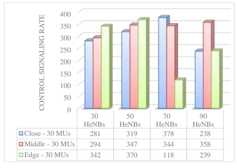
Figure 3 Comparison of control signaling rate of the proposed algorithm in three scenarios: Close, Middle and Edge.
By comparing the control signaling rates between the proposed algorithm and an existing work (Suman's algorithm, 2017), when increasing the femtocell density from 30 to 90 cells in both MU groups (15 and 30), as shown in Figure 4, the proposed algorithm showed a sharp decrease in the control signaling rate. It is noticed that the control signaling rate in Suman's handover scheme increased regularly when the femtocell number and MU number increased. Thus, Suman's algorithm proved that the control signaling duration is fixed on the basis of the femtocell density. Moreover, Suman's handover decision algorithm applied control signaling to all MU's neighboring cells in each measured period by comparing the RSS of MU with its serving cell on the one hand and with MU's neighboring cells on the other hand. However, our proposed scheme significantly reduced the control signaling rate compared to Suman's algorithm for each MU group. This is due to the use of the Q-learning technique on the one hand and the use of the distance parameter between the femtocell location and the current position of the MU on the other hand. Therefore, the MU performs control signaling only with the femtocells that are in the candidate list in order to select the target femtocell, ignoring the other neighboring cells. In addition, the MU performs control signaling with the candidate femtocell list, which is already filtered at angle |25<del>+</del>|, which is another reason for the reduction of the control signaling rate.
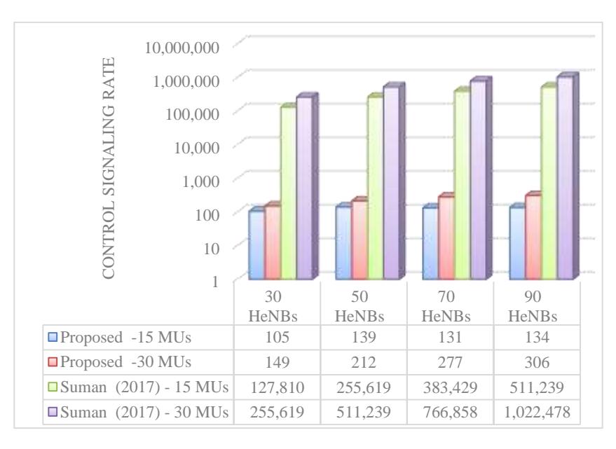
Figure 4 Comparison of the control signalling rate numbers of the two handover algorithms.
Regarding the three scenarios of femtocell distribution (Close, Middle and Edge), the femtocells were distributed to groups of 30, 50, 70 and 90 MUs in each scenario and the number of MUs was configured as 30. Figures 5 and 6 show the simulation results of the proposed algorithm using both CBR and VoIP in terms of packet loss ratio. It can be seen from the two figures that the femtocell number increased the packet loss ratio in all distribution scenarios. Furthermore, both figures show that the lowest packet loss ratio occurred when the femtocell density was in the middle, while the highest occurred when the femtocell density was at the edge. This is because the MU starts moving away from the macrocell tower location and the femtocell density when concentrated close to the macrocell tower, which affects the packet loss ratio by increasing both the handover number and interference.
Furthermore, when the femtocells were distributed at the edge, the packet loss increased because of the weakness of RSS between the MU and its serving macrocell while MU executes hand-out/handover and the femtocell density is smaller than their density when distributed in the middle. In addition, Figure 5 and Figure 6 indicate that the packet loss ratio using CBR was higher than when using VoIP. This is because of the difference in packet size and the priority of real-time application. The packet size of CBR is 512 bytes with a rate of 8 packets/second, while the VoIP packet size is 32 bytes per 20 ms time interval.
By increasing the femtocell density from 30 to 90 cells for each MU group (15 and 30) using the CBR application, both algorithms showed an increase in packet loss ratio, as can be seen in Figure 7. This increment of packet loss ratio was observed as long as the femtocell number was predictable due to frequent handovers between cells, especially among femtocells that cover a small area, and each handover process has a probability of radio link failure (RLF). The proposed algorithm increased the packet loss ratio from 0.00425 to 0.04952 seconds when the femtocell number increased from 30 to 90 and in the case of using 15 MUs. Meanwhile, with Suman's algorithm the packet loss ratio increased from 0.0475 to 0.21588 seconds with the same change in femtocell number and the same number of MUs. In addition, in the case of 30 MUs, the proposed algorithm increased the packet loss ratio from 0.00656 to 0.05504 seconds, while the femtocell number increased from 30 to 90. With Suman's algorithm the packet loss ratio increased from 0.08082 to 0.23619 seconds with the same change in femtocell number using the same application.
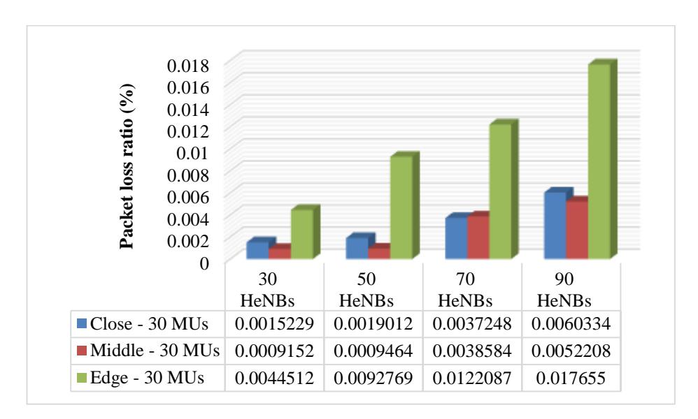
Figure 5 Comparison of packet loss ratio of the proposed algorithm in three scenarios using the CBR application.
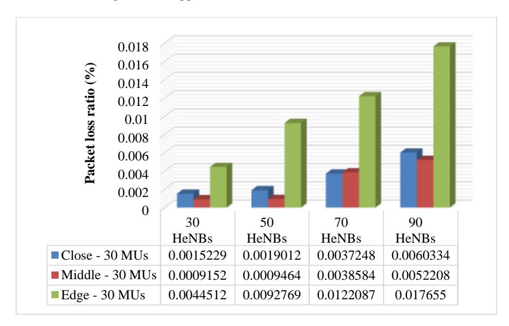
Figure 6 Comparison of packet loss ratio of the proposed algorithm in three scenarios using the VoIP application.
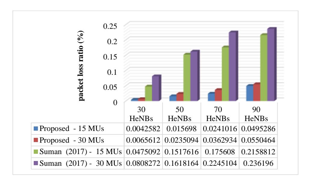
Figure 7 Comparison of packet loss ratio using the CBR application for two handover algorithms.
Nevertheless, the proposed algorithm reduced the packet loss ratio in comparison to Suman's handover for each of both MU groups for each femtocell density using the CBR application. In general, the proposed algorithm with CBR reduced the packet loss ratio by 85.24% compared to Suman's handover algorithm in all scenarios.
With regard to the VoIP application, the two handover decision algorithms were evaluated using different numbers of femtocells (30, 50, 70 and 90) and a specific number of MUs (15 and 30). Figure 8 shows that both handover decision algorithms increased the packet loss ratio as the femtocell number increased. Moreover, the packet loss ratio using the VoIP application was lower compared to using the CBR application.
The proposed algorithm in the VoIP application increased the packet loss ratio from 0.000326 to 0.005587 seconds when the femtocell number increased from 30 to 90 and the number of MUs was 15. Meanwhile, with Suman's handover algorithm the packet loss ratio increased from 0.008664 to 0.02666 seconds with the same change in femtocell number and when using 15 MUs. Additionally, in the case of using 30 MUs and the same change in femtocell number, the packet loss ratio showed variation in the results in comparison to the packet loss ratio when using 15 MUs with both algorithms because of the effect of the number of MUs. The packet loss ratio in the proposed algorithm increased from 0.001459 to 0.00728 seconds when the femtocell number increased from 30 to 90. In addition, the packet loss ratio increased from 0.02318 to 0.03707 seconds with the same change in femtocell number for Suman's algorithm. However, the proposed algorithm reduced the packet loss ratio compared to Suman's handover algorithm for each MU group and for each femtocell density using the VoIP application. Generally, the proposed algorithm combined with the VoIP application reduced the packet loss ratio by 86.44% compared to Suman's handover algorithm in all scenarios.
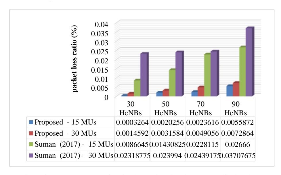
Figure 8 Comparison of packet loss ratio using the VoIP application for two handover algorithms.
However, the proposed algorithm showed the lowest packet loss ratio with both applications compared to Suman's handover algorithm for each MU group and each femtocell group. The reason why the proposed algorithm had a lower packet loss ratio is the efficiency of the Q-learning scheme and ignoring all neighboring femtocells that are not within the range of MU movement. In addition, the selection of the target femtocell on the basis of the closest distance and smallest \(\theta\) has a good effect on the reduction of redundant handovers, as each handover process has a probability of handover failure, which is reflected in the packet loss ratio. Furthermore, it is also noted from the figure that the packet loss ratio increased with both algorithms when the MU number was changed from 15 to 30 for each femtocell density. This increment is predictable and is related to the increase in MU density.
4 Conclusion and Future Work
The system performance obtained from the proposed scheme indicates a lower percentage of control signaling rate and packet loss ratio compared to the benchmarks used for this algorithm. The simulation results indicate that the suggested scheme based on the Q-learning methodology can help to improve the handover stage in LTE-A systems.
Choosing appropriate factors to enhance the cell selection stage is still a hot research topic. Consequently, we recommend further work to be designed and implemented in this field, including load balancing, hybrid femtocell schemes and UE velocity.