
1 Introduction
Researchers have given increased attention to designing multi-frequency planar antennas to meet the requirements for wireless communication systems. A slot antenna can fabricate multi-frequency antennas and achieve a low profile, perfect isolation, and simple incorporation into other planar circuits [1]. In addition, some designers have developed slot antennas to obtain multiband operation [2-4]. However, it has been found that the slot antenna has inherent weaknesses: fabricating size, poor gain, return loss, and VSWR. Recently, compact and small-sized antennas have been widely developed. Besides giving size-related
advantages, these antennas also offer optimal radiation as well as feasible integration features. These features facilitate easy antenna integration with other circuits on one substrate, usually referred to as system-on-substrate (SoS).
Substrate integrated waveguide (SIW) technology can be used for presenting SoS. SIW ensures the successful integration of active and passive components on the same substrate. In addition to this, SIW technology also facilitates SoS to reduce the circuit size. SIW cavity-backed slot antennas are a well-known type of antenna with a SIW structure [5]. This approach is suggested for overcoming the large size and bidirectional radiation of the classical slot waveguide antenna. However, they also have a narrow bandwidth. The large size, low gain, and narrow bandwidth are significant limitations that impact the performance of SIW cavity-backed slot antennas in planner circuits.
The size of a SIW cavity-backed slot antenna can be reduced/minimized by applying a meander slot on the ground layer of the antenna [6]. With this approach, a cavity with an upper resonance frequency added by the meander slot can also be used [7]. Besides this, a compact ridged SIW antenna can also achieve this purpose [8]. It is important to note that the meander slot's location – on the antenna's ground plane – can cause a shift of the resonance frequency to a lower frequency. However, the ground plane's space is limited [6,7].
Another method of minimizing the antenna's dimensions is to cut the magnetic field at the SIW in two. If the SIW's magnetic field is divided by an asymmetric plane – in the transmission direction – it results in keeping half of the magnetic field distribution unaffected [9]. This is referred to as the half-mode substrate integrated waveguide (HMSIW) structure. HMSIW was first presented in 2006 by Hong, et al. [9,10]. Based on the HMSIW structure, the dimensions of the slot antenna will be reduced by approximately 50 per cent, as stated in [11,13]. However, HMSIW can also use for attaining multiband frequency, as noted by [13]. In addition, a larger electric field can quickly achieve by the placement of a radiation slot on an open plane (see Figure 1).
The main challenge with SIW antennas is to achieve a simple integration with solid isolation and low loss [7]. Another constraint in SIW antenna design is minimizing the number of antennas in the transceiver system; compact multiband antennas are in high demand but have lower gain and efficiency [8]. As a result, HMSIW technology has been proposed to overcome the drawbacks previously mentioned.
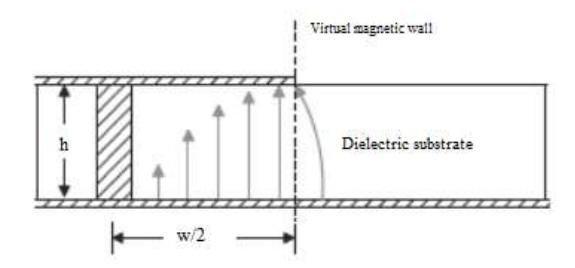
Figure 1 Setting and electric field model of the HMSIW structure [4].
This paper introduces a new HMSIW frame with a slot on the top plane. The developed HMSIW structure was successful in reducing the total dimensions of the antenna up to 50%. However, a Hilbert slot has been added to acquire a tripleband frequency response and similar radiation determinations. The dominant resonance frequency, using the Hilbert slot on the top plane, leaves the measurements unaffected. The outcome of these experiments gives reasonable verification without degrading the efficiency of the SIW antenna in S- and F-band applications. The three contributions of this paper are the following:
- 1. Miniaturization was achieved on the transverse side using HMSIW technology compared to SIW technology.
- 2. We are providing triple-band characteristics.
- 3. The proposed antenna is powerful, light-weight, planar, and low-profile, making it ideal for wireless medical device applications.
2 Related Work
Several researches conducted to make antennas compactly work at lower frequencies with high performance. In [14], the researchers suggested HMSIW technology for a frequency-reconfigurable antenna to reduce the dimensions. Ref. [15] introduced the design of a single-layered HMSIW squared cavity-backed antenna that gives execution radiation in comparative full-mode SIW. The structure in [16] is a dual-frequency antenna using HMSIW for WLAN application. It works at the 2.45 GHz and 5.8 GHz frequencies and provides a size decrease of almost 50% compared to regular SIW antennas. The designs reported in [17] propose two paradigms for examining the field distribution and determining the phase constant of the HMSIW and radiation properties. In [18], the researchers focused on reducing a frequency scanned leaky-wave antenna utilizing HMSIW for OSB Ku-band. Miniaturization was accomplished on the transverse side using an HMSIW innovation compared with LWAs dependent on SIW innovation. An HMSIW-based antenna with a semi-hexagonal resonant slot for WBAN applications was designed to provide a compact SIW antenna [19]. A semi-hexagonal space was scratched on the top cladding to control the centre frequency of the cavity at 5.8 GHz. Ref. [20] proposed a compact two-band frequency using an HMSIW antenna for WBAN applications at 5.8 GH and WLAN applications at 5 GHz. A semi-hexagonal slot is often mounted on the top plane of a semi-hexagonal HMSIW cavity for radiation emission. A new model of HMSIW cavity-backed antenna is studied and presented to achieve crosspolarization and high gain in [21]. The HMSIW technique is effective in transforming the non-emanating cavity into a radiating aperture without applying a radiating slot. Ref. [22] used a combination of an HMSIW cavity resonator with a conventional SIW cavity to enhance the dimensions of the antenna and achieve good gain and performance.
In the current work, an HMSIW technique with a slotted antenna on the top layer uses. This antenna was designed to reduce the dimensions and multiband frequencies used in S- and C-band applications.
3 Procedure Design
The HMSIW technique is one of the most effective methods to reduce antenna dimensions by half while keeping the SIW antenna operating at the same characteristics [22]. It requires some modifications, characterized by adding a scaled-down copy of the Hilbert slot in the centre of each of the three primary slots. The HMSIW antenna design method is explained in the following paragraphs. In addition, this technique is suitable for designing multiple frequencies for producing multiband antennas. HMSIW reduces the dimension of the antenna by half compared to traditional SIW antennas without affecting the performance of the antenna. The dimensions of the Hilbert slot [23], etched on the top plane of the HMSIW antenna, is shown in Figure 2.
Figure 2 Dimensions of the Hibert slot.
Figure 3 illustrates the HMSIW antenna with three Hilbert slots, reducing the size to half the dimensions of a conventional SIW antenna. As a result, the width of the HMSIW can determine according to Eq. (1) [24]:
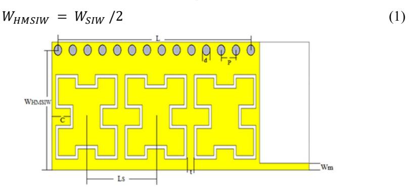
Figure 3 The SIW antenna has three slots.
The simulated response of the above HMSIW antenna is presented in Figure 4. This antenna operates on a single band frequency of 9 GHz. This operating frequency value was doubled due to the reduction of the antenna dimensions by half.
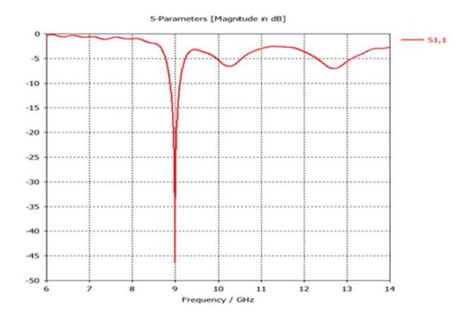
Figure 4 The simulated response of the HMSIW antenna.
In order to make this antenna operate with the exact specifications as a conventional SIW antenna, a scaled-down copy of the Hilbert slot with different ratios was added to the centre of each primary slot (illustrated in Figure 5). It found that a ratio of 65% is more appropriate in this design because the other ratios gave bad return loss and gain results.
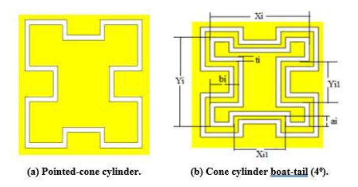
Figure 5 Proposed Hilbert cell and its embedded form: a,) proposed cell, b) scaled-down form.
The geometrical configuration of the proposed Hilbert-HMSIW antenna is shown in Figure 6. The equivalent circuit of the proposed HMSIW antenna is not different from a Hilbert-SIW antenna but takes equivalent elements of an inner Hilbert slot into consideration.
Figure 6 The layout of the modelled scaled-down Hilbert-slot HMSIW antenna.
4 Parameter Study and Simulation Result
The design presented in this paper was simulated using the CST software. This antenna was fabricated by triple slots on the FR4 substrate with a height of 1 mm and a dielectric constant of 4.3. The dielectric loss quantifies the inherent indulgence of electromagnetic energy, which can be denoted by loss angle δ. The overall antenna size, including transmission line, was 26 mm × 9.5 mm, which is relatively compact compared to a conventional Hilbert-SIW antenna with the same thickness. Several parameters were studied to determine the effectiveness of the proposed system. In general, all parameters had a minor effect on the antenna response, except Xi (width of the inner Hilbert slot) and ti (the dimension of one trace of the inner slot etched on the top). Figure 7 shows the dependency of the third frequency band on the Xi parameter. The position of the third band frequency increased as Xi was increased.
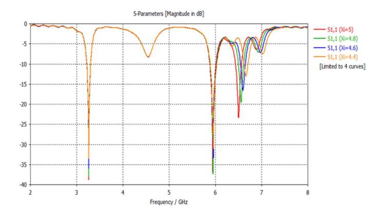
Figure 7 Simulated S11 response of the proposed HMSIW antenna with Xi as a parameter.
The other parameter that affected the designed antenna was ti. From Figure 8, as ti increased, the first band frequency was minimally affected. However, it decreased the centre frequency of the second and third bands and the value of return loss (match between antenna and transmission line). One of the disadvantages of this design is the difficulty of fabricating on a small scale.
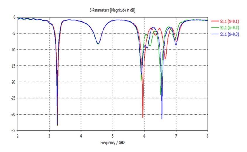
Figure 8 Simulated response of the proposed antenna with ti as the parameter.
Table 1 gives the final dimensions of the proposed antenna. The result of the simulation, related to the return loss and gain, is shown in Figures 9 and 10, respectively, related to the triple-band characteristics.
The first band frequency was 3.25 GHz, the bandwidth was 0.0968 (2.97%), the return loss was -38.77, the gain was 3.56 dBi, the total and radiation efficiency was -1.219 dB (75.52%) and -1.253 dB (74.93%), respectively. As the difference between the two efficiency values was 0.034, the loss of impedance mismatch was low. The second band frequency was 5.94 GHz, the bandwidth was 0.134 GHz (2.25%), the return loss was -35.82, the gain was 4.97 dBi, the total and radiation efficiencies was -0.441 dB (90.33%) and -0.493 dB (89.2%), respectively. As the difference between these two- efficiency values was only 0.0184, the loss of impedance mismatch was low.
| Table 1 Dimensions of the proposed HMSIW antenna with three Hilb | ert cells. |
|---|
| Parameter | Value (mm) Parameter | Value (mm) | |
|---|---|---|---|
| L | 19.5 | Xo1 | 2.25 |
| \(W_{HMSIW}\) | 8.9 | Yo1 | 1.75 |
| P | 1.5 | \(a_{o}\) | 0.75 |
| d | 0.8 | \(b_o = bi\) | 1.5 |
| Wm | 0.5 | ti | 0.25 |
| LS | 7 | Xi = Yi | 5.25 |
| t | 0.75 | Xi1 | 3.25 |
| C | 1.875 | Yi1 | 2.8 |
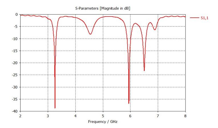
Figure 9 Response of the HMSIW antenna with three Hilbert cells.
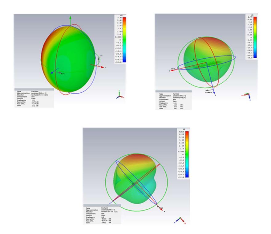
Figure 10 Far field 3D-plot gain of HMSIW (a) 3.25 GHz, (b) 5.94 GHz, (c) 6.5 GHz.
The third centre frequency was 6.5 GHz, the bandwidth was 0.149 GHz (2.29%), the return loss was -23.35, the gain was 6.432 dBi, the total and radiation efficiencies was -0.5676 dB (87.74%) and -0.586 dB (87.3%), respectively. As the difference between these two efficiency values was only 0.0184, the loss of impedance mismatch was low. However, there was an unwanted frequency value, i.e. 4.5 GHz, because the return loss was very high. In addition, some design parameters of the proposed HMSIW antenna – as listed in Table 1 (C = 1.875 mm, t = 0.75 mm, ti = 0.25 mm etc.) – require high fabrication accuracy. This is a problem that will cause difficulties in the manufacturing process. The sensitivity of these parameters was the reason for the differences between the theoretical and the practical results.
4.1 Electrical Field and Magnetic Field (H-field) Distributions
Figure 11 shows the mechanism radiation model of the E-field and H-field at an operating frequency of 3.25 GHz in three planes, XOY, YOZ, and XOZ. The normalized radiation model of the E-field and H-field (proposed antenna) at a resonating frequency of 5.94 GHz in three planes, XOY, YOZ, and XOZ, is shown in Figure 12.
Figure 13 gives the simulated field radiation patterns in three planes, XOY, YOZ, and XOZ, at 3.25 GHz.
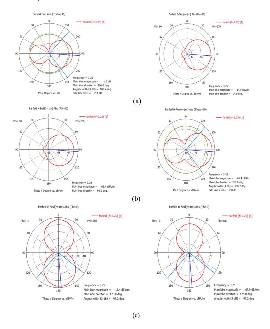
Figure 11 Simulation polar plot of radiation patterns in the E-plane and H-plane at 3.25 GHz: (a) XOY plane, (b) YOZ plane, (C) XOZ plane.
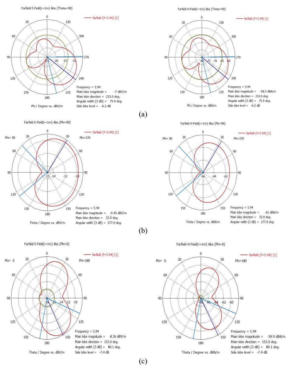
Figure 12 Simulation polar plot of the radiation patterns in the E-plane and Hplane at 5.94 GHz: (a) XOY plane, (b) YOZ plane, (C) XOZ plane.
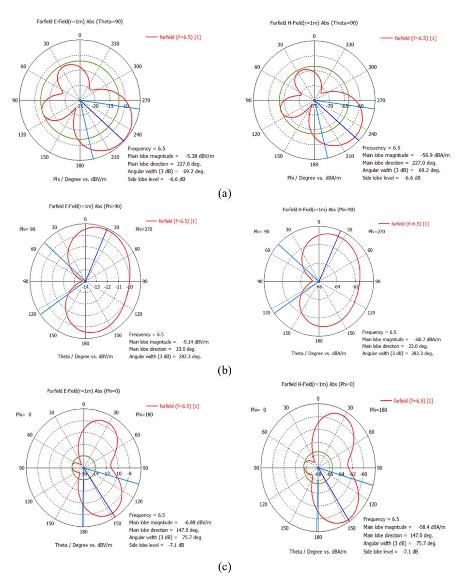
Figure 13 Simulation polar plot of radiation patterns in the E-plane and H-plane at 6.5 GHz: (a) XOY plane, (b) YOZ plane, (C) XOZ plane.
4.2 Surface Current Distribution
The surface current mainly concentrated on the gap between the Hilbert cells and the input port, as depicted in Figure 14(a). However, the current density was low at the centres of these cells because the inner Hilbert cells prevent the flow of current into the centre.
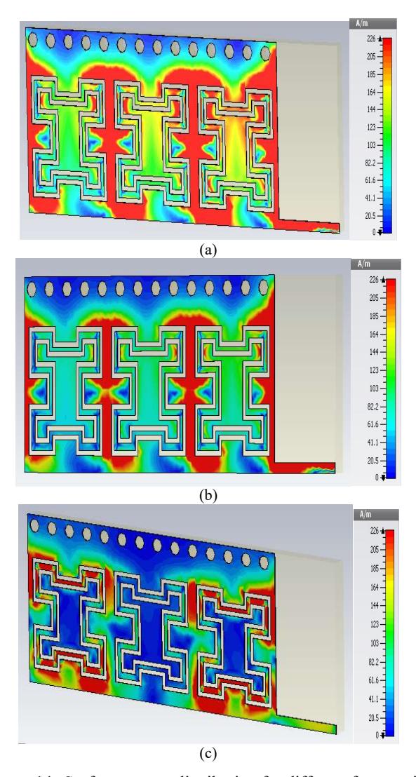
Figure 14 Surface current distribution for different frequencies.
4.3 Antenna Implementation and Comparison Between the Measurement and Simulation Result
Based on the numerical analysis and simulation results described in this paper, an experimental three Hilbert-slot HMSIW antenna was implemented. The fabricated prototype of the developed antenna is shown in Figure 15.
Figure 15 Photograph the fabricated prototype of the three Hilbert-slot HMSIW antennas: (a) front view, (b) back view.
Figure 16 depicts the measured and simulated S-parameter, respectively. Excellent agreement between the measurement and simulation results observed. The fabricated antenna achieved triple-band characteristics. The first centre frequency was 3.25 GHz, the bandwidth was 0.6 (16.4%), the return loss was - 27.34 dB. The second centre frequency was 5.85 GHz, the bandwidth was 0.5 GHz (8.5%), the return loss was -33.2 dB. The third centre frequency was 6.6 GHz, the bandwidth was 0.2 GHz (3.03%), the return loss was -20.55 dB.
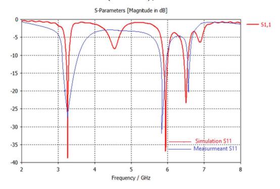
Figure 16 Comparison between the simulated and measured parameter for prototype three Hilbert-cell HMSIW antenna.
Figures 17,18, and 19 show the measured and simulated gain of the triple-band operating frequency.
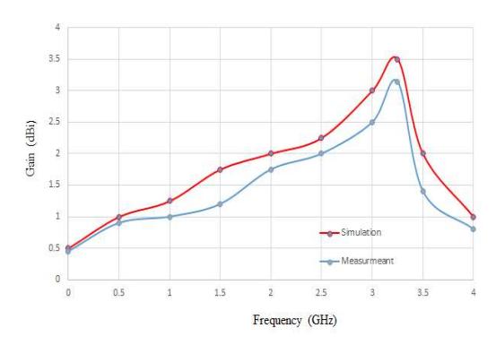
Figure 17 Gain comparison between simulation and measurement at 5.94GHz.
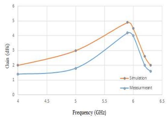
Figure 18 Gain comparison between simulation and measurement at 3.25GHz.
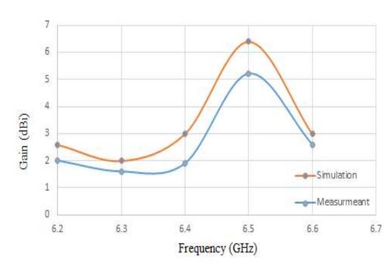
Figure 19 Gain comparison between simulation and measurement at 6.5GHz.
Table 2 summarizes the comparison of the simulated and the measured results for the proposed HMSIW antenna. There was good agreement between both results. The comparison between the simulated and the measured gain at the trip resonant frequency showed good agreement. The measured gain at 3.25 GHz, 5.85GHz and 6.6 GHz was 3.14 dBi, 4.1dBi and 5.22 dBi, respectively. However, there was some deviation between the measured and simulated values, which may be due to imperfections in the fabrication process. The first and second frequencies' measured BW were increased by 5.53% and 2.2%, respectively, due to additional loss from SMA (Sub Miniature Version A) connector, not included in the simulation result. It is clear that the measured BW at the first resonant frequency was increased, and the return losses increased in all resonant bands. This is probably due to the unspecified \(\varepsilon r\) value and possible fabrication errors.
Table 2 Test model specifications and test conditions.
| Parameters | fo (GHz) | BW (%) | S11 (dB) | Gain (dBi) |
|---|---|---|---|---|
| Simulation results | 3.25 /5.94/6.5 | 2.97/2.25/2.29 | -39/-36 /-24 | 3.56/4.97/6.43 |
| Measured results | 3.25/5.85/6.6 | 8.5/4.45/3.03 | -29/-32/-20 | 3.14/4.1/5.22 |
The proposed antenna is compared with other antennas in Table 3. In comparison to the antennas proposed in [11,19,20,25], the proposed antenna is relatively small. About the reference antennas, there is also an increase in fractional impedance bandwidth. The proposed architecture, it can be concluded, has the advantages of a triple-band. As a result, the proposed antenna's efficiency and characteristics were improved.
Table 3 Summarizes the comparison of the proposed design of an HMSIW antenna in terms of simulated and measured results.
| Parameter | Resonant Frequency (Ghz) | Bw (%) | S11 (Db) | Gain | Total Efficiency (%) | Directivity (Db) | Antenna Size (Mm) |
|---|---|---|---|---|---|---|---|
| [11] 2016 | 8.5/ 10.6 | 2.75/ 3.42 | -22/ -20 | 7.5/ 6 | Did Not Mention | Did Not Mention | 30 * 17 |
| [19] 2019 | 5.8 | 3.8 | -27 | 6.1 | 83 | 6.909 | 44*24.5 |
| [20] 2018 | 5/5.8 | 3/3.1 | -38/ -33 | 6.25/ 6 | 81.5 | 6.888 | 32.7 * 44 |
| [25] 2018 | 4.5/9.3 | 3.7/ 6.77 | -23.4/ -40.12 | 4.41/ 5.76 | 73.11/ 82.33 | 5.791/ 6.6 | 26 * 19 |
| Our Proposed | 3.25/ 5.85/ | 16.4/ 8.5 | -27.34/ -33.2/ | 3.14/ 4.1/ | 75.5/ 90.33/ | 4.35/ 4.54/ | 26 * 9.5 |
| Model | 6.6 | /3.03 | -20.55 | 5.22 | 87.74 | 5.767 |
5 Conclusion
A new antenna design based on HMSIW was introduced to decrease the dimensions of the antenna by half and produce triple-band characteristics for practical wireless communication applications. The model's main advantage is that it is simply because it only needs etched slots on the top plane of the antenna to increase the wavelength. This makes the antenna capable of operating at lower frequencies while ensuring lower return loss, higher bandwidth, and gain than conventional SIW antennas.
The proposed HMSIW antenna was designed and fabricated using a multilayer substrate PCB process. There was reasonable agreement between the experimental and the simulation results. However, there was a slight difference in the frequency band and the centre frequency. This was mainly because of the unspecified value and possible fabrication errors. Also, there was a slight difference related to the return loss due to SMA connector losses. Using HMSIW technology, many integrated circuits such as microwave- and millimetre-wave circuits are manufactured utilizing this strategy. By using another shape for the HMSIW antenna, for example, hexagonal, with the same slots of the proposed antenna, a follow-up study will extend this work to enhance the HMSIW gain. The designer in [26] used a half-mode SIW cavity with a high length-to-width proportion, which helps produce a high-gain radiation pattern of the antenna. Applications of 3.25 GHz are within the S-band (2 to 4 GHz) utilized by the radars of airports for ensuring surveillance and control of air traffic, surface ship radar, weather radar, and other communication satellites. Applications of 5.94 and 6.5 GHz are within the C-band (4 to 8 GHz), which is utilized for different satellite communications transmissions, cordless phones, Wi-Fi devices, and weather and surveillance radar systems.