
1 Introduction
Data security is an important aspect in various communication fields, for instance multimedia frameworks, medical imaging, and military communications. However, the data exchange process in a physical channel or in a software implementation; remains vulnerable if this data or this exchange is not properly protected [1]. Various forms of data, such as text, images, sound, or video, can be exchanged. However, the exchange of image data has special requirements given the intrinsic characteristics of images, such as the intra-correlations of their structures and the large memory space they require [2].
In cryptography, a standard-compliant encryption scheme must introduce two properties: confusion and diffusion. These properties have been identified by Shannon in his work Theory of Communication in Secrecy Systems [3].
According to Shannon's original definition, in image encryption, the confusion property corresponds to a desire to make the relationship between the encryption key and the cipher-image as complex as possible. And the diffusion property indicates that the statistical redundancy between the pixels of a plain-image must be dissipated in the statistics of the cipher-image. In practice, the correlation between the pixels of the plain-image must not be found in the cipher-image [4].
Besides these two properties, Feistel [5] recommends an additional and important notion: the avalanche effect property. In image encryption, this property quantifies the fact that even small differences between two plain-images lead to very big difference between their cipher-images. Thus, each bit of the plainimage must contribute to the calculation of each bit of the cipher-image. In practice, avalanche effect measurement quantifies the effect of a small change in the plain-image, or key, on the cipher-image.
In this context, all these notions must be considered as design constraints to be satisfied.
The proposed color image encryption scheme is based on three sub-processes: the first process introduces diffusion; the second process introduces confusion; and the third process defines the avalanche effect property.
The rest of this work is organized as follows: The proposed color image encryption scheme's general architecture is presented in the section 2. Before explaining the proposed encryption scheme's overall process in section 4, the third section is reserved for a deep development of the three sub-processes composing this overall process. The implementation of the proposed color image encryption scheme and its performance analysis will be discussed in section 5. Finally, the sixth and last section concludes the work.
2 The Architecture of the Proposed Encryption Echeme
The architecture of the proposed color image encryption scheme, as shown in Figure 1, is based on a harmonized integration of three sub-processes:
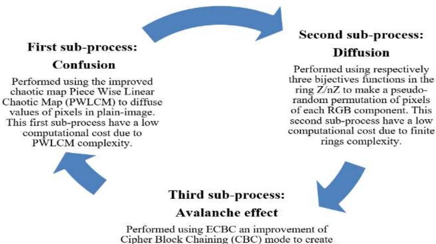
Cipher Block Chaining (CBC) mode to create sequential and chaotic modification of pixels of each color image RGB component obtained from the second process through. This third subprocess have a low computational cost due to CBC complexity.
Figure 1 The proposed encryption scheme architecture.
The first sub-process, relating to confusion, is based on the piece-wise linear chaotic map (PWLCM) [6]. The second sub-process, relating to diffusion, based on a three bijective functions in the ring \(\mathbb{Z}/n\mathbb{Z}\) [7]. Finally, the third sub-process relating to avalanche effect is based on an improvement of the Cipher Block Chaining (CBC) operation mode to ensure optimal cryptographic properties in the block cipher-image [8]. This architecture based on the combination of the three sub-processes, aims to add and increase confusion, diffusion and the effect avalanche property.
3 The Three Sub-processes of the Architecture
3.1 The First Sub-process: the Confusion Generator
The first sub-process, the confusion generator, based on the piece-wise linear chaotic map [6] is defined in Eq. (1) as follows:
\[\text{[rumus tidak dapat ditampilkan dengan baik — lihat PDF asli]}\] where x(n) ∈ [0, 1] ; ≥ 0; with (0) is the initial condition and p the control parameter. For p ∈ ]0, 0.5[ the map x(n) has chaotic behavior without any window in its bifurcation diagram.
The PWLCM chaotic map was chosen because of the perturbation technique it uses, on the one hand to enhance the chaotic dynamics and on the other hand to increase and control the period of the generated chaotic sequences.
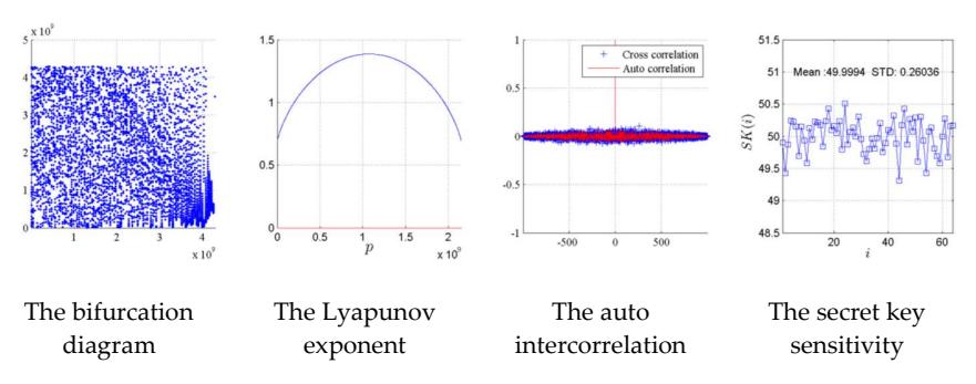
Figure 2 The performance of PWLCM.
The cryptographic performances including that of PWLCM as shown in Figure 2 have been proven by Li et al. [9-10]. PWLCM presents random behavior (uniform invariant density function), more positive Lyapunov exponents, an exponential autocorrelation on attenuation [9], and high sensitivity to initial conditions.
3.2 The Second Sub-Process: The Diffusion Generator
The second sub-process, the diffusion generator, based on a chaotic permutation to shuffle pixels. A permutation of some objects is a particular linear ordering of the objects. The permutation function must be bijective, which guarantees a reversible algorithm.
The adopted bijective function [7] for the proposed scheme is defined in Eq. (2), as follows:
\[f(x) = (m * x + w) mod(n)\] (2)
According to Euler's theorem [11], an application is bijective if and only if the multiplier coefficient is prime with n .
The value of each pixel is changed by the bijection modulo 16, witch defines a permutation in the ring ℤ/16ℤ. Recall that the ring ℤ/nℤ is the set formed by the expression Eq. (3):
\[\mathbb{Z}/n\mathbb{Z} = \{ k \in \mathbb{Z}, 1 \le k \le n - 1 \text{ and } \gcd(k, n) = 1 \}\] (3)
Therefore, any bijection () where is the size of the image , welldefines a linear congruence generator in ℤ/16ℤ.
3.3 The Third Sub-Process: The Avalanche Effect Generator
The third sub-process, the avalanche effect generator, is based on a robust improvement of the Cipher Block Chaining (CBC) mode [8]. CBC, as explained in Figure 3, applies an exclusive-OR (XOR) operator to each block with the encryption of the previous block before it is itself ciphered in the same process, applying the bitwise XOR operator to the first plain-image block and the random initialization vector (commonly referred to as IV). The vector has the same size as a plain-image block.
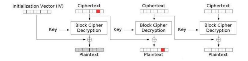
Figure 3 Cipher Block Chaining (CBC) mode encryption.
In CBC encryption mode, block decryption is closely linked to the previous blocks for encryption, witch makes the avalanche effect a default property of this mode. However, the CBC mode has several drawbacks. Let MC(i) be the i-th clear pixel and DC(i) its associated ciphered pixel, then:
- 1. any error on DC(i) will affect only MC(i) and MC(i+1);
- 2. for an error that affects the last block, all previous blocks are not affected;
- 3. the initialization vector IV is random but unique (leads to brutal attacks);
- 4. the initialization vector is not linked to the ciphered data.
To overcome these drawbacks, a corrective improvement is proposed. Pseudo random values for IV are generated from the chaotic map and data obtained from the second process. Thus, the initialization value for IV depends on the encryption key and the plain-image context respectively.
The new initialization vector IV is proposed in Eq. (4) as follows:
\[\begin{cases} k = (\sum_{i=1}^{n} Vc(i)) \text{ mod}(n) \\ \rho = Vc(k) \\ n \\ VI = \rho \bigoplus_{i=1}^{n} MC(i) \end{cases}\] \[(4)\] where \(\bigoplus\) is the bitwise operator and MC is the clear data of n blocks and Vc the chaotic vector obtained by the Eq. (1).
By using the enhanced CBC encryption mode, the ciphered DC data are obtained according to Eq. (5):
\[\begin{cases} DC(1) = VI & \text{for } i = 1 \\ DC(i) = DC(i-1) \bigoplus MC(i-1) & \text{for } i > 1 \end{cases}\] (5)
Further, changing the block to position q, Eq. (4) becomes Eq. (6):
\[VI = \rho \bigoplus MC(1) \bigoplus MC(2) \bigoplus ... \bigoplus MC(q') ... \bigoplus MC(n)\] (6)
Furthermore, performing the XOR operation between Eqs. (4) and (6) gives (7):
\[MC(q) \oplus MC(q') = 0 \tag{7}\] which is false, as \(MC(q) \neq MC(q')\).
Hence, a change of MC= (1) results in all changes in DC(i), and since Eq. (4) is non-linear, less disturbance in the input image or in the key will cause a great disturbance in the output image. Indeed, the former confusion is implemented in ECBC mode; this allows adding a retroaction mechanism, creating the avalanche effect as a result.
4 The Overall Process: The Encryption Generator
The overall process of the proposed encryption scheme is a series of integration of the three previously developed sub-processes: the confusion, the diffusion and the avalanche effect generator sub-processes.
4.1 The Overall Encryption Process
The overall encryption process is as follows:
- 1. Read the 24 bits color image.
- 2. Extract the three matrix color channels, MR, MG and MB.
- 3. Construct the chaotic vector PW under constraint size(PW) = \(3 \times L \times M(1)\) by using Eq. (1).
- 4. Put the three matrices MR, MG and MB in the form of three vectors \(V_r\), \(V_g\) and \(V_b\) of size L \(\times\) M.
- 5. Construct the chaotic vectors \(PW_r\), \(PW_g\) and \(PW_b\) of size \(L \times M\), from vector PW generated in Step 3.
- 6. Realize the confusion vectors \(V_r\), \(V_g\) and \(V_b\)with vectors, \(PW_r\), \(PW_g\) and \(PW_b\)according to Eq. (8) below:
\[\begin{cases} V_{\alpha}x(i) = V_{\alpha}(i) \oplus PW_{\alpha}(i) \\ \alpha = R, G \text{ or } B \end{cases}\] (8)
7. Construct a linear bijection in Z/nZ (n = LxM) according to Eq. (2) gives rise to the formula (9):
\[f_{\alpha}(V_{\alpha}x) = (m_{\alpha}.V_{\alpha}x + w_{\alpha}) \bmod(n)\] (9)
with \(m_{\alpha}\) first with size n (the number of integers \(m_{\alpha}\) is equal to \(\phi(n)\) with \(\phi\) is the indicator function of Euler).
with \(m_{\alpha}\) is prime with n (the number of integers m is equal to \(\phi(n)\) with is the indicator function of Eule
- 8. Permutate the position of the pixels in vector \(V_{\alpha}x\) by three \(f_{\alpha}\) functions that are generated by using Eq. (9).
- 9. Construct the chaotic initialization vector \(IV_{\alpha}\) with the following steps
- 10. Calculate the chaotic vector sum in \(\mathbb{Z}/\mathbf{n}\mathbb{Z}\) by Eq. (10) defined by:
\[S_{\alpha} = \left(\sum_{i=1}^{n} PW_{\alpha}(i)\right) \mod(n) \tag{10}\] a. Assign the value of chaotic vector to position \(S_{\alpha}\) to \(X_{\alpha}\) by using Eq. (11)
\[X_{\alpha} = PW_{\alpha}(S_{\alpha}) \tag{11}\]
b. Applying a bitwise operator on all values of \(V_{\alpha}p\) with \(X_{\alpha}\) using Eq. (12):
\[IV_{\alpha} = X_{\alpha} \bigoplus_{i=1}^{n} V_{\alpha} p(i)\] \[i = 1\] (12)
11. Apply the CBC encryption mode by applying Eq. (13):
\[\begin{cases} V_{\alpha}a(1) = IV_{\alpha} & \text{for } i=1 \\ V_{\alpha}a(i) = V_{\alpha}p(i-1) \oplus V_{\alpha}a(i-1) & \text{for } i>1 \end{cases}\]
- 12. Transform the vec. obtained in three matrices RC, VC and BV (size \(L \times M\)).
- 13. View the ciphered color image.
4.2 The Overall Decryption Process
To reconstruct the plain-image, the overall verall decryption process is simply the reverse order of the encryption process.
5 Results And Performance Analysis
In the performance analysis experiments, three test images were chosen from the USC-SIPI image database [12], as shown in Figure 4.
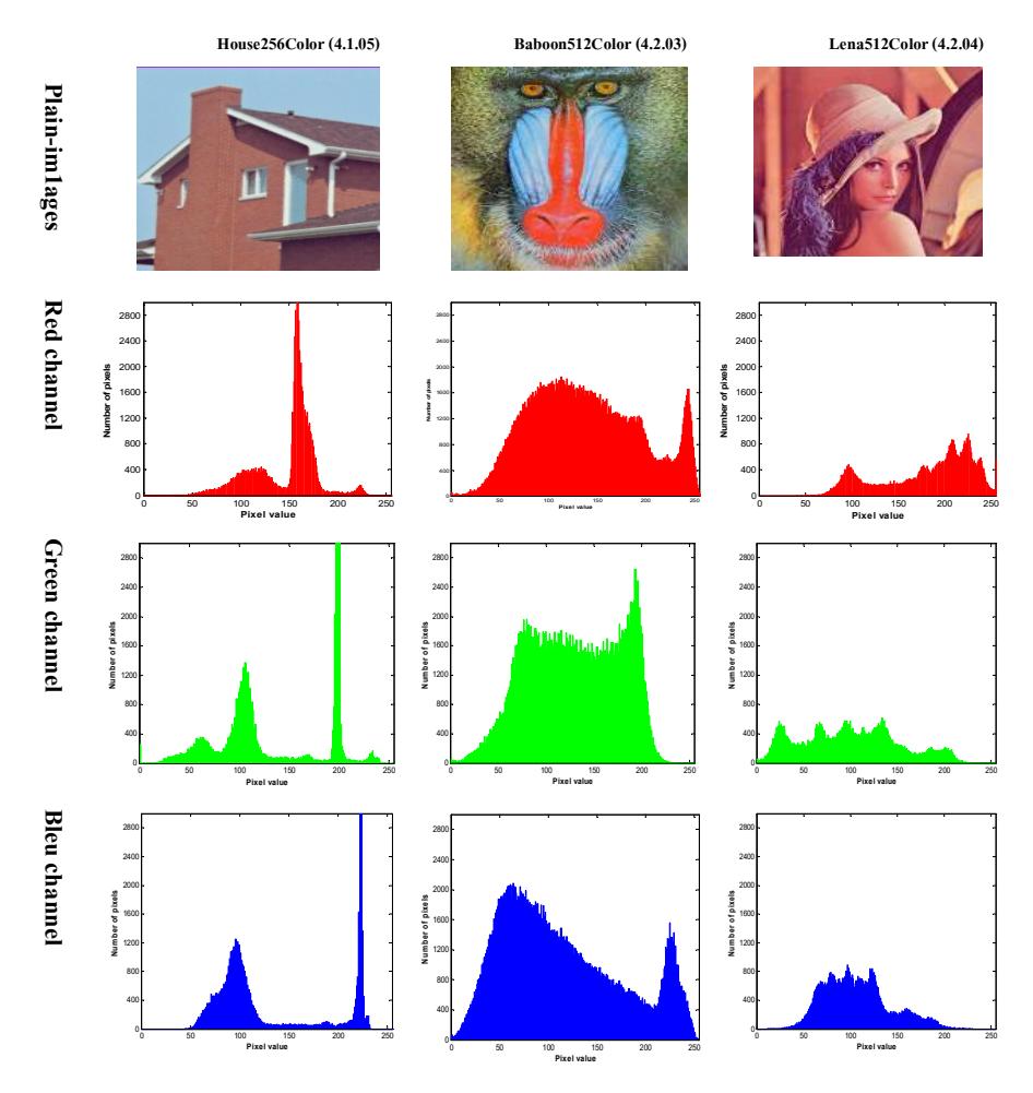
Figure 4 The three plain test images and their associated histograms.
| House256Color (4.1.05) | Baboon512Color (4.2.03) | Leas12Color (4.2.04) | |-----------------------------------
The three ciphered test images with their associated histograms are grouped together in Figure 5.
Figure 5 The three ciphered test images and their associated histograms.
The performance of the proposed encryption scheme was measured using several analyses: computational cost, key space, randomness test (differential), histogram analysis, adjacent pixel correlation and entropy analysis.
5.1 Computational Cost Analysis
The complexity of an algorithm is an expression of how much time, space, or other resources the algorithm will use. The complexity calculation of the proposed encryption scheme gives a value of \(\theta\)(n2). In the programming phase, a computer was used with the following technical characteristics: intel i5 CPU, 2.53 GHz with 4 GB of RAM running on Windows 10 Professional and Java (Eclipse compiler).
To evaluate the running speed of the proposed scheme, tests were executed a considerable number of times and then the average was obtained. The average encryption/decryption times for the three test images are shown in Table 1.
Images House256Color (4.1.05) Baboon512Color (4.2.03) Lena512Color (4.2.04) Encryption Decryption Encryption Decryption Encryption Decryption time(s) time(s) time(s) time(s) time(s) time(s) 0.096 0.093 0.147 0.267 0.141 0.176
Table 1 The running time of the proposed encryption scheme.
According to the results of Table 1, the average running time for the 3 test images was very fast. These robust performances are justified by the computational cost reduction strategy used in the integration of the three sub-processes.
5.2 Key space Analysis
The proposed encryption scheme is very secure since a 128-bit size key is used, witch negates any exhaustive attack since it requires 2128≈3,.4 x 1,038 attempts.
5.3 Differential Analysis
The avalanche effect means that a small change in the plain-image or key should create a significant change in the cipher-image. The number of pixels change rate (NPCR) and the unified averaged changed intensity UACI are the two most used metrics to evaluate avalanche effect and differential attacks [13-14].
NPCR and UACI are computed using Eqs. (14) and (15) respectively:
\[NPCR = \frac{\sum_{i,j} D(i,j)}{L \times W} \times 100 \%\] (14)
\[UACI = \frac{1}{L \times W} \left( \sum_{i,j} \frac{\left| C1(i,j) - C2(i,j) \right|}{255} \right) \times 100\%\] (15)
where W and H are the width and height of the image, respectively. C1(i, j) and C2(i, j) are the ciphered images before/after one pixel of the plain-image is changed. For position (i, j), if \(C1(i, j) \neq C2(i, j)\), then D(i, j) = 1; else D(i, j) = 0.
The higher the value of NPCR and UACI, the better the designed algorithm is. Acceptable values are 96% for NPCR and 33.45 for UACI [13-14].
Table 2 Values of NPCR and UACI for testing images.
| Image | Image size | UACI(%) | NPCR(%) |
|---|---|---|---|
| House | 256 x 256 Color | 33.6727 | 99.3461 |
| Baboon | 512 x 512 Color | 33.4412 | 99.5528 |
| Lena | 512 x 512 Color | 33.4579 | 99.2149 |
According to the results in Table 2, the NPCR and UACI for the three test images were within the norms with robust values (NPCR<sub>expected</sub>=99.61%, UACI<sub>expected</sub>=33.46%) [13-14]. As a result, the encryption scheme has robust resistance to exhaustive attacks.
5.4 Histogram Analysis
The histogram is a statistical analysis [15-16] that shows the distribution of an image's pixels. Ideal image encryption schemes generate a cipher-image with a histogram that has a uniform distribution. As can be seen in Figure 5, the histograms were very uniformly distributed and significantly different from the plain-image histograms, which makes statistical attacks more difficult to apply.
5.5 Adjacent Pixel Correlation Analysis
The analysis of the correlation coefficient [15-16] evaluates the correlation between adjacent pixels and hence assesses the robustness of the algorithm. The correlation coefficient of adjacent pixels is calculated with Eq. (16):
\[r_{xy} = \frac{\text{cov}(x,y)}{\sqrt{D(x)}\sqrt{D(y)}}\] (16)
Where x, y are two vectors formed respectively by the values of the image's selected sequence pixels and the values of their adjacent pixels. The cov(x,y), E(x) and D(x) are calculated with Eqs. (17), (18) and (19), which are defined as follows:
\[E(x) = \frac{1}{N} \sum_{i=1}^{N} x_i\] (17)
\[D(x) = \frac{1}{N} \sum_{i=1}^{N} [x_i - E(x)]^2\] (18)
\[cov(x, y) = \frac{1}{N} \sum_{i=1}^{N} [x_i - E(x)][y_i - E(y)]\] (19)
where N is the number of adjacent pixels selected in the image to calculate the correlation coefficient; \(x_i\) and \(y_i\) are, respectively, the elements of x and y.
The graphic verification and evaluation of the correlation between adjacent pixels for the Lena test image yielded the results shown in Figures 6 and 7. To situate the proposed method, it was compared with two methods [17-18]. For the Lena, the results of average correlations are grouped in Table 3.
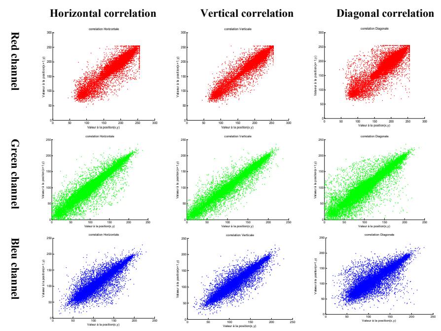
Figure 6 Lena plain-image: the horizontal, vertical and diagonal adjacent pixel correlations for each RGB channel.
According to the graphical and analytical results grouped in Figure 7 and Table 3, the proposed encryption scheme satisfies the zero co-correlation property, and thus its robustness against statistical attacks is fulfilled. According to this comparison, our method is well situated and better than the two methods chosen.
Table 3 Average RGB channel correlations and comparison.
| Image | Plain-image correlations | Cipher-image correlations | |||||
|---|---|---|---|---|---|---|---|
| horizontal | Vertical | diagonal | horizontal | Vertical | Diagonal | ||
| Method [15] | House | 0.8669 | 0.7321 | 0.7321 | -0.0030 | -0.0095 | -0.0259 |
| Baboon | 0.9324 | 0.9653 | 0.9161 | -0.0243 | -0.03016 | -0.0246 | |
| Lena | 0.9341 | 0.9726 | 0.9191 | -0.0048 | -0.0112 | -0.0045 | |
| Method | House | 0.879324 | 0.932969 | 0.816038 | 0.003149 | -0.006062 | 0.009519 |
| [16] | Baboon | 0.985813 | 0.977835 | 0.986258 | -0.006508 | -0.003598 | -0.043443 |
| Lena | 0.970850 | 0.954886 | 0.950905 | -0.001587 | -0.014706 | 0.002381 | |
| Our method | House | 0.967086 | 0.935256 | 0.912852 | -0.008841 | 0.000493 | 0.001834 |
| Baboon | 0.987341 | 0.973537 | 0.967769 | 0.005903 | -0.000597 | -0.000137 | |
| Lena | 0.974186 | 0.981908 | 0.958263 | -0.011147 | 0.003422 | -0.004887 | |
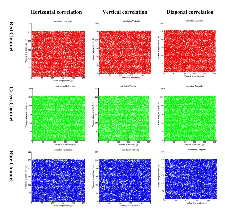
Figure 7 Lena cipher-image: the horizontal, vertical, and diagonal pixel correlations for each RGB channel.
5.6 Entropy Analysis
Information entropy H [19] measure the uncertainty related to random variables. The information entropy H(S) of a message source S is defined by Eq. (20):
\[H(S) = \sum_{i=0}^{k-1} p(s_i) \log_2 \frac{1}{p(S_i)}\] (20)
where \(p(s_i)\) denotes the probability of symbol \(s_i\) and k is the total states of the information source. In the case of a uniform distribution, the entropy H (S) is maximum and is given by Eq. (21):
\[H_{\text{max}} = \log_2(2^8) = 8 \tag{21}\]
The more uniform the distribution of pixel values, the greater the information entropy. A perfect encryption scheme has entropy close to ௫ = 8 .
For the three test images, the entropies were calculated as presented in Table 4.
Table 4 Entropy measurement results.
| Image | Sizes | Plain-image entropy | Cipher-image entropy |
|---|---|---|---|
| House | 256 x 256 | 7.068625 | 7.999146 |
| Baboon | 512 x 512 | 7.412625 | 7.999878 |
| Lena | 512 x 512 | 7.750197 | 7.999763 |
Based on the measurements in Table 4, the three test cipher-image entropies have values close to the optimal value ௫ = 8 which avoids any entropic attack.
6 Conclusion
In this work, while satisfying confusion/diffusion as one of Shannon's constraints and also satisfying the avalanches effect as one of Feistel's constraints. A novel color image encryption scheme that uses three sub-processes was proposed and implemented. The evaluation proved the robustness of the proposed encryption scheme through high confusion, high diffusion, an enhanced avalanche effect, low computational cost, and a large key space. As a result, the proposed encryption scheme for color images can ensure data storage and transmission confidentiality and integrity while maintaining safety and running speed.