
1 Introduction
1.1 Background
In recent years, the Internet of Things (IoT) trend has been being adopted very quickly. Whitmore, et al. in [1] describe IoT as a concept in which everyday objects are connected with sensing and computing power. An example of an IoT application is a smart home, where household items are equipped with computing power and are connected to the internet to be controlled remotely and have smart features [2]. In the coming years, IoT is expected to develop exponentially and impact the real world in various fields, including agriculture [3], healthcare [4,5], manufacturing, transportation [6], etc. According to Fortune Business Insights [7], the market size of IoT in 2021 was 384.7 billion USD, and it is projected to grow from 478.3 billion USD in 2022 to 2456.2 billion USD in 2029. As a concept that has recently taken off, IoT still has many aspects that need to be developed. According to IoT Analytics [8], the IoT market is influenced by several factors that can accelerate its development, such as the adoption of 5G and the development of artificial intelligence, and factors that can hinder its growth, such as a shortage of chips on a global scale. Therefore, research is needed on various aspects of IoT to facilitate its adoption in society so that people can have the benefits as soon as possible and to the fullest.
Among the aspects that need to be examined regarding IoT is its security. For a concept that is predicted to be adopted by the wider community, it is necessary to ensure that IoT applications adhere to security principles such as confidentiality, integrity, and availability to maintain the security of their users and their systems. One of the topics in the field of IoT security is its access control system, which governs how access to IoT objects is controlled. With the access control system, the parties that can access an IoT object are only those authorized by the authorizing parties. In that regard, an access control system is necessary to protect the data owned by the IoT object or the object itself.
1.2 Related Works
Regarding ACS, according to Jing Qiu, et al. [9], access control is a process to ensure that every request for a resource or data owned by a party is governed by a system that can decide to accept or reject the request. For an access control system to make a good decision to accept/reject a request, the access control system needs to carry out authentication and authorization processes. Authentication is the process of verifying the identity of a user, process, or device, according to NIST's CSRC [10]. In an access control system, authentication is required to ensure that the party requesting access to a resource is genuine and not counterfeit. The authentication process can utilize public key cryptography
[9], in which the cryptographic technique can create a 'secret key', or private key, that can be used to produce messages that can be guaranteed to come from the party with the private key so that authentication can be achieved.
Meanwhile, according to CSRC NIST [11], authorization verifies if a request for an action or service to a specific entity is approved. In an access control system, authorization is the stage after authentication. After a party requesting access to a resource has been authenticated, the access control system will decide whether to accept or reject the access request. In the case of IoT objects, the access control system can forward this decision to the object the user wants to access so that the IoT object will actuate according to the decision received. There are many types of authorization models, such as DAC, MAC, RBAC, and others [9,12]. The authorization model that was the focus of this research is an attribute-based access control (ABAC) based authorization model, in which authorization decisions are made by evaluating the rules for the subject, object, operation, and environment attributes relevant to a request [13]. The advantage of ABAC is the dynamics of the decision-making process because decisions are not only based on the static identity of the requester but also on attributes of the requester for access, attributes of the resource to be accessed, and environmental attributes that can change at any time [14,15]. References [16,17] employed this type of access control for security and privacy-preserving purposes in their systems.
Examples of attributes that can change are the access time, the condition of the resource when you want to access it, and so on. Another type of authorization model is role-based access control (RBAC), in which authorization decisions are made based on the role bound to the access requester [9]. Each role is given provisions regarding its access rights. The access rights allow a logical grouping of the types of requesters. Still, this can create scalability problems if specific authorization rules are desired, as more and more roles have to be created. Chen, et al. [18] proposed an exploration model of RBAC using a hierarchical-assisted approach to reduce time-consuming processes from the overall architectural perspective of role establishment. Petrov, et al. [19] have conducted previous research on many-to-many authentication schemes based on NFC (near field communication) tags. In that study, Petrov, et al. proposed a real-time and noninteractive algorithm for generating encryption/decryption keys from only a department's secret key or a user's secret key and some public information. Petrov, et al. used department and user terms for opposing parties to authenticate each other. Accordingly, there are many departments, identified by , and users, identified by , where and are the serial number of the department and user concerned, respectively. In addition, there is a party called the certification center, which acts as the system administrator.
For all combinations of department number and user number , a symmetric secret key is created, namely ,. This is achieved with the help of a system public key, namely , which is distributed to all departments and users, and a master secret key (MSK), namely ( < ), which only the certification center knows. Petrov et al. proposed the following equations [19]:
\[UKeyj = aUSERj \bmod c \tag{1}\]
\[DKeyi = aDEPi \bmod c \tag{2}\]
\[KEYi, j = (UKeyj)DEPi \bmod c\] (3)
\[KEYi, j = (DKeyI)USERj \bmod c\] (4)
is a secret key only known by the certification center and user number j. This key is created by the certification center and gives the user the number because only the certification center knows the master secret key (). The same thing is also done for . , is a symmetric key that can be generated by department number , user number , or the certification center.
These equations have several implications. First, referring to the discrete logarithm problem, users and departments cannot obtain the master secret key () from or , so users and departments cannot generate keys for other parties in the system. Second, the number of bits of each variable can be determined by determining the bit length of its modulus, namely the system public key (). Third, through Eqs. (3) and (4), it is concluded that department number and user number can create the same information (, ) independently, which cannot be created by other parties so that both parties can mutually verify each other's authenticity (authentication). Thus, a many-to-many authentication scheme is achieved through these equations. In addition, Petrov et al. also explained other things, such as the memory structure in smart cards and the system workflow (certification center setup, adding new departments and users, authentication process, etc.). In addition, Komar, et al. [20] continued the research of Petrov, et al. with additional contributions in developing document storage mechanisms. Reference [21] evaluated SONIK, an electric vehicle charging operation system that involves several charging station providers, e.g., BPPT, Puspiptek, and PT Len Industri. This charging station management system is not secure and does not have an authentication mechanism for the user. According to the above discussions, our paper developed the following hypotheses:
Hypothesis 1. Smart card-based access control can provide security enhancement in electric vehicle charging station management systems.
Hypothesis 2. Many-to-many authentication scheme can be implemented in isolated systems using network security means.
2 Material and Method
This section will explain the core concepts that are important in designing and implementing the system, including the system components and the cryptographic model used to secure the system.
2.1 System Components
The relationship between the system components is visualized in Figure 1. Three types of parties are involved: administrator, institutes, and users. The administrator is an entity that manages the system and interfaces between the institutes and the users. Institutes are entities that have resources that are the subject of access control. The users may access the resources that the institutes have according to their access rights. The users each have a smart card that can contain the access permits that are required to access institute resources. Note that there can be many institutes and many users; hence, it is a many-to-many system. In this many-to-many access control system, a user can access resources from many different institutes. An institute can grant access to its resources to many different users, all using the same system.
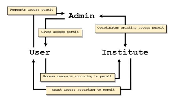
Figure 1 System components relationship diagram.
Regarding the network, it is necessary to determine the best network technology between entities in the institutional subsystem so that communication runs smoothly and system operations have good performance. Ethernet, Wi-Fi, Bluetooth Low Energy, and ZigBee are among the network technologies that can be used as alternatives. In terms of data transmission speed, Ethernet is superior to wireless technologies because it is wired. However, wired Ethernet is difficult to maintain due to the impracticality of having to use cables to connect the IoT objects. According to the data presented in reference [22], Wi-Fi, Bluetooth Low
Energy, and ZigBee technologies are good enough in terms of range and data rate. However, Wi-Fi is superior to Bluetooth Low Energy and ZigBee in terms of interoperability, where Wi-Fi is generally paired with the Ipv4 technology, most used by public servers, in contrast to Bluetooth Low Energy and ZigBee, which require protocol translation to facilitate Ipv4.
Different smart card products are available for use as access control tool for the system. In this case, the choices were narrowed down to two options: MIFARE Classic 1K [23] or MIFARE Desfire EV3 [24]. Functionally, both can support many-to-many access control applications. MIFARE Classic 1K organizes its smart card memory into sectors that can be filled with application data. These sectors can be accessed separately using their respective authentication credentials. Thus, sectors can be utilized to build a many-to-many system. MIFARE Desfire EV3 supports many-to-many authentication schemes through its data organization implemented via filesystems. Filesystems on MIFARE Desfire EV3 can be filled with different documents and have their own authentication credentials, so they can also be used to build a many-to-many system. However, MIFARE Classic 1K has an advantage in terms of price, which was close to IDR 5,000 (< USD 0.4) on the marketplace at the time this article was compiled, compared to MIFARE Desfire EV3, which had a price of around USD 1.82 or IDR 26,000 [25].
2.2 Cryptographic Model
The users' smart card contains data from institutes for access permit purposes. Therefore, a protection mechanism is needed for the smart card using cryptography. The example smart card used was MIFARE Classic 1K [23], which organizes its memory into sixteen sectors. Each sector has three data blocks and one sector trailer. The sector trailer contains two keys and a value called the access bits. The two keys, Key A and Key B, can be used independently as an authentication key to access a sector. The access bits set the read and write permissions for Key A and Key B (see Figure 2).
| Byte number | ||||||||||||||||
|---|---|---|---|---|---|---|---|---|---|---|---|---|---|---|---|---|
| Block | 0 | 1 | 2 | 3 | 4 | 5 | 6 | 7 | 8 | 9 | 10 | 11 | 12 | 13 | 14 | 15 |
| 3 | 𝐾𝐸𝑌𝑖𝑛𝑠𝑡𝑖𝑡𝑢𝑡𝑒𝐼𝑑,𝑢𝑠𝑒𝑟𝐼𝑑 | 𝑎𝑐𝑐𝑒𝑠𝑠 𝑏𝑖𝑡𝑠 | 𝐾𝐸𝑌𝑐𝑒𝑟𝑡𝑐𝑒𝑡𝑒𝑟𝐼𝑑,𝑢𝑠𝑒𝑟𝐼𝑑 | |||||||||||||
| 2 | 𝑏𝑜𝑜𝑘𝑖𝑛𝑔𝐼𝑑 | |||||||||||||||
| 1 | 𝑎𝑠𝑠𝑒𝑡𝑁𝑎𝑚𝑒 | |||||||||||||||
| 0 | 𝑠𝑡𝑎𝑟𝑡𝐷𝑎𝑡𝑒 | 𝑒𝑛𝑑𝐷𝑎𝑡𝑒 | ||||||||||||||
Figure 2 Access permit structure in MIFARE Classic 1K smart card.
To protect the smart card sectors, we can set Key A to be used only by the institute that is assigned to the sector, and Key B to be used only by the administrator
(certification center). We can use the following equations, which are based on the research done by Petrov, et al. [19]:
\[UKey_{userId} = masterKey^{userId} \ mod \ (publicKey) \tag{5}\]
\[IKey_{instituteId} = masterKey^{instituteId} \mod (publicKey)\] (6)
\[KEY_{instituteId,userId} = (UKey_{userId})^{instituteId} \mod (public\_key)\] (7)
\[KEY_{instituteId,userId} = (UKey_{instituteId})^{userId} \mod (public\_key)\] (8)
Eqs. (5) to (8) can ensure that every combination of institute and user has a unique and private Key A only known to the institute, and every user has a unique and private Key B only known to the certification center.
Figure 3 shows a visualization of the characteristics used to protect the smart card. From the picture, each sector will be protected by two authentication keys. One is Key A, which the corresponding institute can only obtain for each sector, and one is Key B which can only be obtained by the administrator. Therefore, no other parties except those two can access the sector. This implementation has two implications. First, isolation is achieved because institutes cannot access the other sectors because Key A is kept private. Second, the administrator can manage the sectors because the administrator has access to all sectors with Key B. Note that smart cards other than MIFARE Classic 1K and MIFARE DESFire EV3 can be used as long as the cryptographic model can essentially be implemented in a corresponding type of smart card.
Figure 3 Illustration of smart card protection using keys.
2.3 System Design
Figure 4 details the system architecture components shown in Figure 1. As can be seen, many users will each have a smart card that they can use to interact with various charging stations from different charging station providers, and an NFCenabled smartphone app to process their smart cards and interact with the administrator's certification center. The many charging station providers will each have many charging station branches, for example, one in city A, one in city B, and so on. Each of the charging stations will be connected to the provider's central server through one or more gateways. These servers interact with the administrator's certification center to process users' access permits. The administrator has a certification center (server) that manages the system's operations according to the mechanisms explained in the following paragraphs.
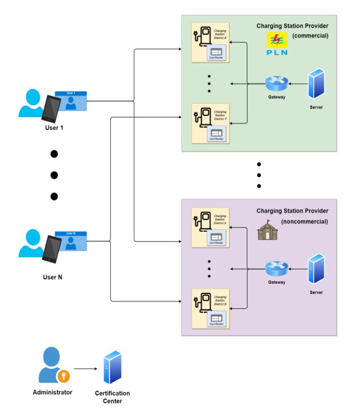
Figure 4 System architecture.
The system mechanisms to facilitate the system's operations can be defined as follows; through these mechanisms, the parties will be able to use the system.
1. Mechanism 0 – Certification center initialization
This mechanism initializes the certification center so it can manage the system. Depending on the implemented system, it may involve setting up a VPN for charging station provider inter-networking, the certification center HTTPS web server, and the cryptographic keys mentioned in the equations above.
2. Mechanism 1.1 – Charging station provider registration
This mechanism is the initial phase of charging station provider integration with the system. This mechanism involves populating the databases in the provider server and the certification center with the identity of the provider for later use. This mechanism differs based on the type of charging station provider, which is explained as follows:
a. Non-commercial charging station provider
Non-commercial charging station providers can determine their own criteria to give an access permit to a user. For example, government institution employees can get an access permit from the corresponding institution if they provide their name, employee id, and address. The provider has to give these data to the certification center when performing registration so the certification center can provide a suitable API to process a booking from the provider.
b. Commercial charging station provider
A commercial charging station provider can give an access permit to a user if the user pays. In this mechanism, the commercial provider has to determine what types of e-wallets they support. This is needed for the certification center to integrate its system with the corresponding ewallet.
3. Mechanism 1.2 – charging station registration
After a charging station provider is registered, it can register its charging station so it will be available to be used by users. This mechanism involves populating the provider database with the identity of the charging station and giving the charging station credentials to access users' smart cards.
4. Mechanism 2 – User registration
In this mechanism, users can register themselves to join the system. This mechanism involves populating the certification center database with the identity of the user. Registered users are given a smart card that will be used to store access permits on a registered charging station.
5. Mechanism 3 – Access permit request by user:
In this mechanism, users can request an access permit to a charging station from a charging station provider by using an NFC-enabled smartphone that can perform read and write operations on their smart card.
The method to obtain an access permit differs according to the type of provider (commercial or non-commercial). The two types of methods are explained as follows:
a. Non-commercial access permits
Users must provide the appropriate credentials when requesting access permits from non-commercial charging station providers. Each noncommercial provider can define these credentials. The certification center and the provider servers must communicate according to the terms agreed upon during the non-commercial provider registration (Mechanism 1.1).
b. Commercial access permits
Users can get an access permit from a commercial charging station provider by paying using an e-wallet that the provider supports. After the payment is confirmed, the certification center will communicate with the provider to give the user an access permit.
After the booking approval process, the corresponding charging station provider will forward the access permit to the certification center. The certification center will then write the access permission to the user's card through the NFC-enabled smartphone app.
6. Mechanism 4 – Granting access to a user
This mechanism involves a user tapping their smart card, which is already filled with one or more access permits gained from Mechanism 3. The provider processes the access permit and performs access control on the charging station. Users will only be given access if they have an access permit to a charging station.
2.4 Mechanisms Detailing
The following paragraph contains a description and details the process of mechanisms defined in Section 2.3.
1. Mechanism 0
In this mechanism, the certification center will be initialized in order to facilitate the administrator's tasks. This mechanism involves the following phases:
- a. Configure VPN and network rules, also register certification center to VPN networks.
- b. Prepare the certification center web server and reader.
- c. Generate cryptographic keys, including the master, public, and private keys.
2. Mechanism 1.1
Mechanism 1.1 defines the initial phase of how charging station providers can be integrated into the system. After registration, the charging station provider can implement access control to its charging stations for registered users. Figure 5 illustrates the process of Mechanism 1.1. Essentially, the certification
center and the charging station provider exchange identity information to be stored in databases in this mechanism.
3. Mechanism 1.2:
In this mechanism, the charging station that registers itself to the server gives its identity to the charging station provider's central server, which is then saved in a database. The charging station provider's server responds with the cryptographic keys that are needed to access users' smart cards (see Figure 6).
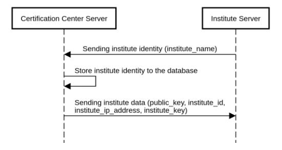
Figure 5 Sequence diagram for Mechanism 1.1.
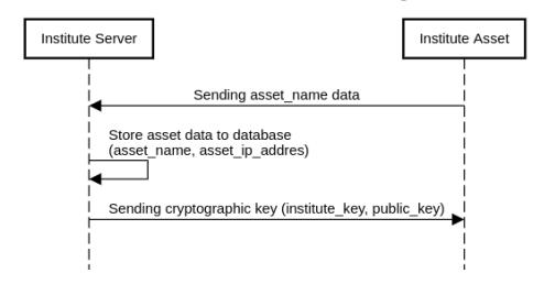
Figure 6 Sequence diagram for Mechanism 1.2.
4. Mechanism 2
In this mechanism, users registering to the system have their identities saved in a database. The user is also given an already configured smart card that can be used to execute the procedures defined in the system (see Figure 7).
5. Mechanism 3
Mechanism 3 defines how users can obtain an access permit that will be used to access the charging station. Figure 8 explains the process of Mechanism 3. In this mechanism, the user requests access to a charging station at the certification center. The certification center then coordinates with the charging station provider to determine whether the request is accepted or denied. The access permit is stored in the user's smart card if he is accepted.
The implementations of Mechanism 3 are not incorporated into the commercial and non-commercial categories. This research is only a proof of concept, so we did not implement this category division. The difference would only be in the initial phase of the access permit request. Non-commercial users give their identity to the certification center, while commercial users can get access permits by paying with an e-wallet. This would have to be appended as part of the mechanism in a real scenario.
Figure 7 Sequence diagram for Mechanism 2.
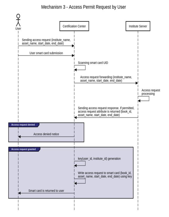
Figure 8 Sequence diagram for Mechanism 3.
6. Mechanism 4
In this mechanism, users that want to access a charging station will tap their card at the scan point in the charging station (see Figure 9). The scan point will then read access permits in the card and forward it to the charging station's provider's server. The server will then decide to accept the access permit, which is forwarded to the charging station so it can be acted upon. Each charging station provider may define the details of the decision-making process, such as using attributes like time as a decision factor, etc.
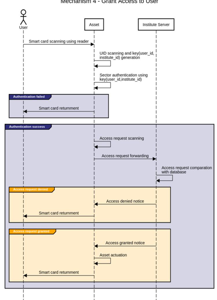
Figure 9 Sequence diagram for Mechanism 4.
2.5 Hypothesis Testing Scenario
Hypothesis 1 states: "Smart card-based access control can provide security enhancement in electric vehicle charging station management systems". In this context, the term 'enhancement' refers to the addition of functionality rather than a quantifiable measure of improvement. The objective is to implement smart card-based access control as an additional layer of security measures. The proposed enhancement involves leveraging smart cards to authenticate and authorize users, ensuring that only authorized individuals can access the charging infrastructure. While quantitative metrics can be employed to evaluate the effectiveness of security enhancements, such as measuring reductions in security breaches or successful unauthorized access attempts, our hypothesis primarily focuses on conceptualizing and implementing smart card-based access control to fortify security measures.
Hypothesis 2 proposes the implementation of a many-to-many authentication scheme in isolated systems using network security means. While this concept may not represent a completely unknown idea, our research emphasizes its practical application and effectiveness specifically within isolated systems, which present unique security challenges. The objective of our study was to contribute to the existing body of knowledge by providing insights into the implementation and benefits of a many-to-many authentication scheme in these systems. While Hypothesis 2 may not pose a research question seeking to uncover unknown information, it served as a valuable objective within our study.
Considering both hypotheses, we did functional testing on data points of the following scenario:
- 1. Given two institutes/charging station providers, Provider A and Provider B.
- 2. Each institution/charging station provider is equipped with one EV charging station: Asset A for Provider A and Asset B for Provider B.
- 3. We have two cards assigned to each institution/charging station provider, representing a total of four users: Card a1, Card a2 from Provider A, and Card b1, Card b2 from Provider B.
- 4. Card a1 and Card b1 have access privileges to both assets (Asset A and Asset B), while Card a2 and Card b2 are restricted to accessing the assets of their respective providers (see Table 1).
- 5. Each card has ten attempts to gain access to each asset.
By simulating this scenario in our functional testing, we aimed to assess the effectiveness and practicality of the proposed smart card-based access control system in providing secure and controlled access to EV charging stations managed by different institutes/charging station providers.
EV Charging Station Asset A Asset B Card Card a1 ✓ ✓ Card a2 ✓ Card b1 ✓ ✓ Card b2 ✓
Table 1 Access matrix.
3 Results and Discussions
In this research, we implemented the system's proof of concept as described in the previous chapters. This section focuses on the evaluation of the proof of concept and is divided into three subsections: detailing each of the mechanisms defined in Section 2.3, implementing all the mechanisms on a test system, and discussion of the results.
3.1 Mechanism Implementation
The high-level architecture of the test system in this research is shown in Figure 10. The system connects the charging station providers and the certification center through a VPN tunnel; specifically, ZeroTier was used in this research. The charging station provider servers were emulated using a Raspberry Pi Zero W, while the certification center server was emulated using a Raspberry Pi 4 Model B. Each server hosted a web server using the Flask framework on Python. The charging station was substituted using a device that consisted of two ESP8266 microcontrollers, an RC522 RFID reader, and an LED to represent the status of the charging station (access permitted or not). The anatomy of this device is shown in Figure 11.
Figure 11(a) shows a schematic diagram of the asset architecture. Three interfaces connect these devices: SPI connects RFID Reader to the reader ESP8266, GPIO sends a signal from the client ESP8266 to the LED and serial communication between both ESP8266s. Figure 11(b) shows the realization of the assets, where the top ESP8266 works as the reader and the bottom ESP8266, which is directly connected to the LED, works as the client. Figure 12 illustrates the workflow of each ESP8266. Since this study focused on the authentication scheme for a manyto-many isolated system, other processes like billing/payment, accounting, and failsafe mechanism, e.g., charging faulty/interrupt, was out of scope and will be proposed in future works. We also did not investigate system performance, such as delay/latency and time complexity.
Each charging station provider has its own server(s) and managed assets, in this case, the EV charging stations. However, this research's focus was solely on the
EV charging stations and the server and smart card were out of scope. In this regard, this paper only mentions trivial information regarding the server, such as server configurations, Mechanism 1.1 (institution/charging station provider registration), Mechanism 2 (user registration, assuming the smart card holders already registered themselves), and Mechanism 3 (user request access permit to perform read and write operations on their smart card).
Generally, each charging station provider has at least one server that operates as database server and web application server concurrently. The database consists of four tables: certcenter, institute, assets, and bookings; the web application server uses seven APIs to operate: homepage, initialize_homepage, initialize_service, register_asset, booking_asset, booking_data, and verify_booking.
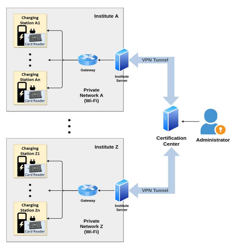
Figure 10 High-level system test architecture.
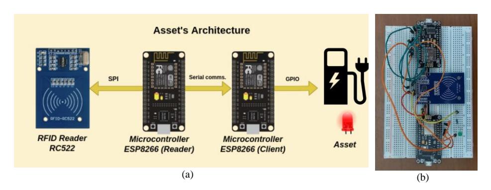
Figure 11 Device schematic diagram (a) and realization (b).
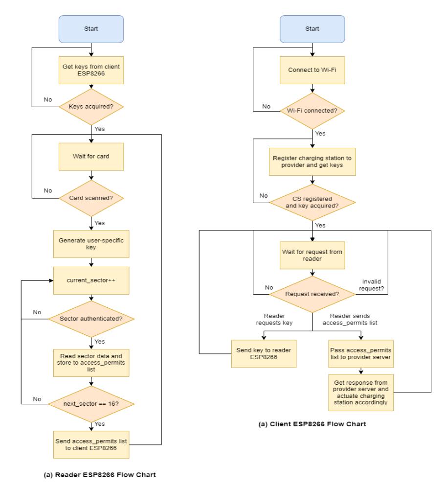
Figure 12 System flowchart of (a) reader ESP8266 and (b) client ESP8266.
3.2 Discussion
There are five main subsystems in the proposed system, namely: smart card, institute/charging station provider server, certification center server, institute assets/charging stations, and network connectivity. The smart card subsystem is created by Mechanism 2 and is actively used in Mechanisms 3 and 4. Charging stations are involved in Mechanisms 1.2 and 4; the network connectivity isolates the traffic between charging station providers. On the other hand, the charging station provider server takes part in Mechanisms 1.1, 1.2, 3, and 4, while the certification center server takes part in Mechanisms 0, 1.1, 2, and 3.
Based on the methodology stated above, the implementation of Mechanisms 0 to 4 succeeded accordingly. Thus, the proof of concept wassuccessful. Furthermore, because Mechanism 4 was this research's core mechanism/behavior, its results will be shown and discussed in more detail. Mechanism 4 is executed by tapping the user's smart card with access permits stored in it and examining the system's behavior. Tables 2 and 3 show the results of Mechanism 2.
| Iteration | Smart card data | Charging station and charging station provider tested | Access permit stored in the database? | Expected Result |
|---|---|---|---|---|
| 1 | 1. Sector 1: access permit for '10kW electricity ' from 'charging station_1' of 'charging | charging-station_1 in charging station provider_A | Yes | Access Granted. Sector 1 can be accessed, Sector 2 not. |
| 2 | station-provider_A' from 01-08-2022 to 01- 11-2022 2. Sector 2: access permit for '10 kW electricity' | charging-station_2 in charging station provider_A | No | Access Denied. Sector 1 can be accessed, Sector 2 not. |
| 3 | from 'charging station_2' of 'charging station-provider_B' from 01-08-2022 to 01- 11-2022 | charging-station_2 in charging station provider_B | Yes | Access Granted. Sector 2 can be accessed, Sector 1 not. |
Table 2 Testing samples for Mechanism 4.
The following is an explanation of the results obtained in both tables, categorized into each component of the system.
1. Smart card
In Table 3, it can be seen that access permits stored in the smart card could successfully be read and sent to the charging station provider's server. In the first iteration, the access permit read in the smart card was only at sector 1 (sector 2 could not be read) because the smart card reader was owned by charging-station-provider_A.
Table 3 Mechanism 4 testing samples result.
| Iteration | Smart card data as read by the charging station | Access request response from provider server | Description |
|---|---|---|---|
| 1 | { "uid": "29f39c98", "access_permits": [ { "sector": 1, "access_permit" : { "book_id": "35783ac6e2bf40d6935dd352f5 171018", "asset_name ": "726f636b000000000000000000 000000", "start_date ": "3233303432303232", "end_date": "3235303432303232" | { "permitted": true } | The charging station is allowed to be accessed. An access permit that matches the smart card data exists in the database. Only the sector that contains an access permit from the corresponding charging station provider is allowed |
| 2 | } } ] } { "uid": "29f39c98", "access_permits": [ { "sector": 1, "access_permit" : { "book_id": "35783ac6e2bf40d6935dd352f5 171018", "asset_name ": "726f636b000000000000000000 000000", "start_date ": "3233303432303232", "end_date": "3235303432303232" } } ] } | { "permitted": false } | to be read (sector 1). The charging station is not allowed to be accessed. An access permit that matches the smart card data does not exist on the database. Only the sector that contains an access permit from the corresponding charging station provider is allowed to be read (sector 1). |
| 3 | { "uid": "29f39c98", "access_permits": [ { "sector": 2, "access_permit" : { "book_id": "30b0f33b21e846d98090ec4a46 5e00a9", "asset_name ": "6c616d70000000000000000000 000000", "start_date ": "3233303432303232", "end_date": "3235303432303232" } } ] } | { "permitted": true } | The charging station is allowed to be accessed. An access permit that matches the smart card data exists on the database. Only the sector that contains an access permit from the corresponding charging station provider is allowed to be read (sector 2). |
Since the access permit was stored in the database, the user could access the charging station. In the second iteration, the access permit read in the smart card was only at sector 1 (sector 2 could not be read) because the smart card reader was owned by charging-station-provider_A. Since the access permit was not stored in the database, access to the charging station was prohibited. In the third iteration, the access permit read in the smart card was only at sector 2 (sector 1 could not be read) because the smart card reader was owned by charging-station-provider_B. Since the access permit was stored in the database, the user could access the charging station. Through the iterations, it can be concluded that access control was successfully implemented according to the access permit, and isolation inter charging station provider was achieved.
2. Charging station
As shown in Table 3, the charging station could read access permits that were contained in the smart card and communicate with the charging station provider's server to obtain an access control decision. This shows that the proof of concept of the charging stations implementing the access control rules was successful.
3. Charging station provider
Tables 1 and 2 show that every test iteration produced the expected response. The server's API successfully received, parsed, and produced the response sent back to the charging station. The API received the access permits contained in the smart card in a JSON form, which informed the UID of the smart card and each access permit information, namely the sector in which it was contained, the booking ID, the name of the charging station, and the start and end date of the access permit. The API sent a response in JSON form, which was simply a Boolean key and value indicating whether access is granted.
4. Certification center
Previously, it was stated that Mechanisms 0 to 4 were successfully implemented since Mechanism 4 is functionally based on the prior explanation. The following is an example of the testing result of the certification center through Mechanism 2 in Figure 13. It can be seen that the charging station provider was able to register and successfully obtain its credentials, namely publicKey and instituteKey.
Figure 13 Mechanism 1.2 testing result.
5. Network latency
From the above analysis, it can be seen that mechanism functionality was achieved. In addition, the latency performance of the implemented system was also tested, by measuring the delay from the tapping of the smart card until the actuation of the access control decision by the charging station (on mechanism 4). Table 4 shows that the latency result indicates that the test system was not yet sufficiently good to be used in a real-world scenario. This result was expected as this research did not consider the performance side of the system.
Table 4 Network latency testing result.
| Iteration | Latency (seconds) |
|---|---|
| Iteration 1 | 4.878 |
| Iteration 2 | 4.709 |
| Iteration 3 | 4.665 |
| Iteration 4 | 4.731 |
| Iteration 5 | 4.802 |
| Average | 4.757 |
This latency could partially be attributed to network delay, however, the biggest contributor to the delay was reading the smart card contents. Currently, in the algorithm used, the reader iterates through all sectors. Each iteration may involve authenticating to each particular sector, which takes a relatively long time. So, while the proof of concept was shown to be successful, the latency performance still needs to be addressed for the system to be implemented in real use cases. This will be done in a future work, possibly by designing a more performant algorithm in Mechanism 4.
3.3 Hypotheses Evaluation
The evaluation was based on the provided scenario in Subsection 2.5 and the assumption that the access control system operates as intended. Table 5 shows the result of this scenario. The access attempts appear to align with the expected results and accuracy for the combination of each asset and card.
Asset Name Card Name Number of Attempts Pass Fail Expected Result Accuracy Asset A Card a1 50 50 0 Pass 100% Asset A Card a2 50 50 0 Pass 100% Asset A Card b1 50 50 0 Pass 100% Asset A Card b2 50 0 50 Fail 100% Asset B Card a1 50 50 0 Pass 100% Asset B Card a2 50 0 50 Fail 100% Asset B Card b1 50 50 0 Pass 100% Asset B Card b2 50 50 0 Pass 100%
Table 5 Scenario testing result.
For Asset A, Card a1 and Card a2 both had successful access attempts in all 50 tries, meeting the expected pass result with a 100% success rate. Similarly, Card b1 also had a 100% success rate for accessing Asset A. However, Card b2 encountered failures in all 50 attempts to access Asset A, resulting in a 100% fail rate. For Asset B, Card a1 had a 100% success rate, successfully accessing Asset B in all 50 attempts. However, Card a2 encountered failures in all 50 attempts to access Asset B, resulting in a 100% fail rate. Card b1, on the other hand, had a 100% success rate for accessing Asset B. Similarly, Card b2 had a 100% success rate for successfully accessing Asset B in all 50 attempts.
These results demonstrate that the access control system successfully enforced the access privileges assigned to each card, allowing only authorized cards to gain access to the corresponding assets while denying access to unauthorized cards. The high success rates for the authorized cards and the corresponding fail rates for the unauthorized cards indicate an effective implementation of the smart cardbased access control system in managing access to the EV charging station assets.
These findings support Hypothesis 1, suggesting that the smart card-based access control system provides security enhancement in electric vehicle charging station management systems. The results further reinforce the value of implementing such a system to ensure secure and controlled access to assets while maintaining the expected access restrictions based on the assigned privileges. The successful access of Card a1 to Asset B, which belonged to a different service provider, demonstrates the implementation of a many-to-many authentication scheme within the isolated systems using network security means. The utilization of a VPN to interconnect the isolated systems allows for secure communication and access between the assets of different service providers. Therefore, based on the test results indicating successful cross-provider access and the presence of network security means through the VPN, it is appropriate to conclude that the test results support Hypothesis 2. The implementation of a many-to-many authentication scheme in isolated systems using network security means was effectively demonstrated in this scenario, facilitating secure access to assets across different service providers.
4 Conclusions
In this research, an access control system using smart cards to implement a manyto-many isolated authentication scheme was designed for an EV charging station provider's system. The system involves three types of parties: an administrator to manage the system, providers who own charging stations whose access can be controlled, and users who can access the charging stations owned by the providers. A many-to-many scheme was achieved through this research's architecture and system mechanisms. 'Isolation' of the system was achieved through network security implementation with the usage of a VPN and the HTTPS protocol and through the protection of the smart cards through a cryptography scheme. The implemented charging station provider subsystem comprised charging station and provider server components. The charging station assets were simulated through two ESP8266 MCUs, an RC522 RFID reader, and an LED as indicator. The charging station provider server was simulated through a Raspberry Pi Zero W single-board computer using Python with Flask as the web server and SQLite as a database. Every component of the system was successfully implemented and tested functionally.
The findings from the hypothesis testing supported both hypotheses. The results strongly supported Hypothesis 1, indicating that smart card-based access control provides a significant enhancement in security for electric vehicle charging station management systems. The functional testing conducted in the experiment demonstrated the successful enforcement of access privileges, allowing authorized cards to access the corresponding assets while denying access to unauthorized cards. The results supported Hypothesis 2, which proposes the implementation of a many-to-many authentication scheme in an isolated system using network security means. Scenario testing revealed that the implemented system effectively differentiated between cards representing different service providers and facilitated cross-provider access to assets. The utilization of a VPN to interconnect the isolated systems ensured secure communication and access between the assets of different service providers. This successful implementation of a many-to-many authentication scheme using network security means within an isolated system underscores its feasibility and practicality in enhancing the overall security and access control mechanisms.
Future research could extend the scope to a complete end-to-end charging station management system, focusing on proposing billing/payment and accounting features, failsafe mechanism, and system performance evaluation. A billing/payment and accounting feature could enable the charging stations to charge the electric vehicle owners for the amount of electricity consumed during the charging process. This would ensure a fair and transparent billing process, payment, and power consumption/money spent for both charging station providers and users. Furthermore, a failsafe mechanism, e.g., charging faulty/interrupt, will be proposed in a future work. This mechanism will ensure that any faults or interruptions during the charging process are detected and resolved promptly to prevent any damage to the charging station or the electric vehicle. It is worth noting that system performance, such as delay/latency and time complexity, were outside of the scope of this study. However, in a future work, we plan to evaluate the performance of the system and propose ways to improve its efficiency and reduce its time complexity.
Acknowledgment
This research was funded by Riset Kolaborasi Indonesia (RKI) 2022 of the Ministry of Education and Culture, Research, Technology.