

1. INTRODUCTION
The most accurate methods used in modern astro-photometry are undoubtedly the photoelectric ones. In 1956 an attempt has been made to introduce this method of measuring light intensities of stars at the Bosscha Observatory, using the 24" double refractor. The high voltage for the dynodes of the photomultiplier of type RCA-1P21 was obtained from dry batteries, which however degenerated very rapidly owing to the great humidity at the observatory. Nothing has been done in this field since then, till late in December 1962 a new attempt was made, using a stabilised high voltage supply for the dynodes of the 1P21 photomultiplier, which the author built at the Mount Stromlo Observatory of the Australian National University, during his stay in Australia.
2. THE TELESCOPE
As the 24" double refractor is continuously used for double star observations, the photoelectric photometer is attached to the 37 cm Bamberg-Schmidt refractor. The objective of this instrument was a refigured one from a 38 cm aperture and 1250 cm focal length objective to an objective of 37 cm aperture and 700 cm focal length by Mr. B. Schmidt. The refiguring has made the lenses too thin, so that their own weight causes a change in the shape of the star images in different positions of tlrc telescope. However, by reducing the aperture of the objective down to 12", by putting a diaphragm in front of the objective, the quality of the star image in different positions of the telescope was found to be a little bit improved. The second disadvantage by using this refractor for photoelectric work is the vibration of the telescope by a slight wind. The instrument is namely housed in a building with a sliding roof which can be rolled northward. As a matter of fact, this system of housing is very disadvantagious for a telescope of seven meter length. Not seldom observations had to be stopped only because of the shaking of the telescope by a slight wind. A dome would have been much better.
The view is restricted between three hours East and thr'ee hours West of the meridian and between 25" North and 50o South in declination. The finder of the refractor is pi'ovided with an eyepiece with a zenithprism.and can be used as a guiding telescope.
3. THE PHOTOMETER
The photometer is constructed chiefly according to the principles by Kron, the light receiver being either a photomultiplier of type RCA-lP2l or an EMI-type one. Figures l, 2 and 3 sholv rough drawings of the instrument, wh.ile Plate I is a photograph of it and Plate 2 shows the photometer attached to the 37 cm Bamberg-Schmidt refractor.
The photometer may be devided into three parts according to their function as follows:
- a. the photometerhead,
- b. the photomultiplier,
- c. the measuring device.
The three parts will be described in the order named.
a. The photometerhead:
This is a brass cylinder of 76 rnm diameter. It is screwed into the focus end of the telescope (R). As the light of a star passes thlough the photometerhead, it first goes th,rough a drilled metal diagonal mirror (l), beiore it reaches the filter (2). While the light of the centered star goes through the hole of tire milror, the lightbeam of a fieldstar, if there is any, will be reflected into an optical system (3), consisting of a microscope objective, a net of crosswires, illuminated by a small electric lamp and an eyepiece. The jntensity of illumination of the crosswires can be changed
Fig. 1. Cross-section of the photoelectric photometer.
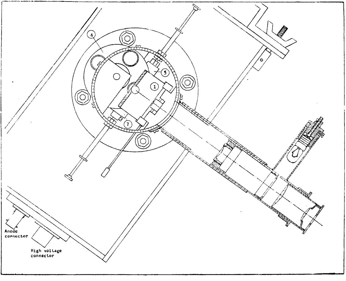
Fig. 2. Cross-section of the guiding-microscope.
Plate 1. A photograph of the photoelectric photometer.
by means of a potentiometer. This microscope then enables the observer to guide with the main telescope. In the case there is no bright fieldstar in the close neighbourhood of the measured star, the observer is referred to the finder for guiding the telescope. This microscope is found to be necessary, especially when the photometer will be used for \(\triangle m\)-measurements of double stars. The diaphragm used for this kind of work has to be chosen as small as possible in order to measure only one component, without being disturbed by the light of the other component of the double star. In this case guiding the telescope carefully is necessary.
Behind the metal mirror lies the filterplate (4), with four holes of 14.1 mm diameter, containing a 2 mm thick UG2, 1 mm thick BG12 cemented to 2 mm thick GG13, a 2 mm thick G G11 and a 2 mm thick Corning 2424. All filters for U, B, and V are glass filters from Schott & Gen. Jena. This filterplate can be rotated easily from outside the brass cylinder, when the filter in the lightbeam has to be changed. A radium mark on the back of the circular disc, which shines in the dark, shows the kind of filter, which lies in the beam of the incoming light.
Next to this filterwheel, a small circular disc of 9 mm diameter (5), containing a standard radium source, which is used as an artificial star of constant luminosity, can be withdrawn from the lightbeam from outside the photometerhead by means of a pin as shown on Fig. 2 (AS).
In the focalplane of the telecsope is the diaphragmplate (6), a circular disc, like the filterwheel, rvith a number of holes of varying sizes from 0.4 mm to 8.0 mm diameter. When the 37 cm refractor is used, this diaphragmplate is put halfway between the two foci for blue and yellorv colour. Since this diaphragmpiate is not as thick as the filterwheel, it is not possible to put some marks on the back of tite plate, to show the size of the diaphlagm, which lies in the lightbeam. Instead of that, a pushpull prism (7) can be inserted in the beam of the incoming light, which throws this beam into a small eyeiriece (8). With this microscope the focalplane diaphragm can be inspected easily. This diaphragniplate too can be rotated from outside the brass c1'linder. A circular window of l" diameter forms the entrance into the cellbox. In order to keep the cell room lighttight, a sliding cover is put in front o[ the circular window, which can be operated from outside the cylinder. Leaving the pierced metal mirror in the position oblique to the optical axes, withdraw the disc with the artificial source (5), prism (7) and cover (9) from the lightbeam, the light of the star will be focussed by the Fabryfield lens (i0) on the sensitive cathode (ll) of the photomultiplier.
The Photomultiplier: b.
During the testperiod, an RCA-type 1P2l photomultiplier was used. This tube is enclosed in a small light-tight brass container, which is housed in a small box of l0 x l0 X l0 cm (12). This box can be filled with dryice to refrigerate the tube in order to decrease the dark current. This small cold box is in turn put in a larger box, which could be firmly locked to the photometerhead by means of four screws. As the Fabry-field lens is close to the cold box, a heating system is made to prevent the lens from fogging. Since dry ice is not easy to get and as the dark current of the lP2l tube is found to be high at room temperature at the observatory, an attempt has been made to operate the pholometer rvith an EMI-type of multiplier, which does not need any refrigeration, when it is operated at the correct interstage dynode voltage. This EMI-tube is housed in a Iight-tight cylinder of blass of 57 mm diameter, as shown in Fig. 3. By means of an alluminium circular disc (A) this brass cylinder could be locked tightly to the photometerhcad. This tube is provided with a Fabry-field lens too.
The measuring device:
By means of two coarial cables the photometer is connected to the highvoltage supplier and the d.c.-amplifier. As a measuring device, a Brorvn-Potentiometer is conl.iected to thc d.c.-aurpiific.r. The box, contaiuing tire higli-voltage-supply, as well as the d.c.-amplifier, is put on
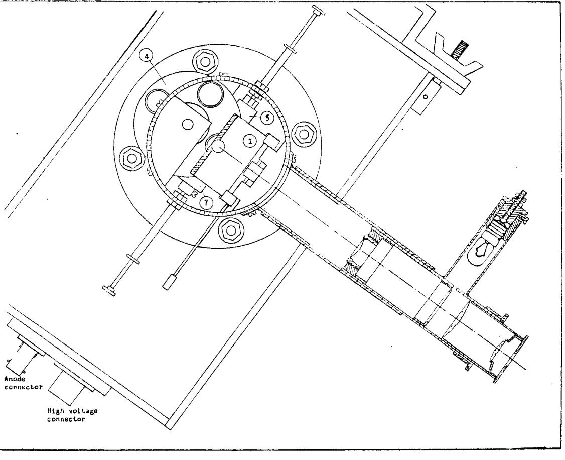
Fig. 2. Cross-section of the guiding-microscope.
top of the Brown-recordeL, which in turn is screwed very tightly on a small rigid table, movable on four rubber rvheels (Plate 2). During the observations this table can easily be moved to any position in the observatory building and consequently can always be placed conveniently with regard to the telescope and the observer. A seperated stabilised high voltage suppliei, speciai built to provide the EMI-type of multiplier with the correct voitage for the dynodes is placed on tiris movable table
Plate 2. The photometer attached to the 37 cm Bamberg-Schmidt refractor. Underneath is the movable table with the d.c-anrplifier on toD of the Brown-Dotentiometer.
too (not shown on the plate). As the high voltage supply as well as the d.c.-amplifier are built in one and the same box, as can be seen on Plate 3, special attention was paid to the cables for the high voltage (11) and anode current (10).
Fig. 4 is the circuit diagram of the power- and high voltage supply, the d.c.-amplifier and the filament regulator for the two E80F tubes of the amplifier.
Plate 3. A bottom view of the d.c-amplifier and high voltage supply.
7. THE MEASUREMENTS
Since the weather conditions at the Bosscha Observatory, Lembang are generally not very favourable from the photoelectric photometric point of view, only a small couple of measurements have been made during the test period in 1962. The construction of the photometer itself as well as some reparations on the refractor were timeconsuming. The very few clear hours,
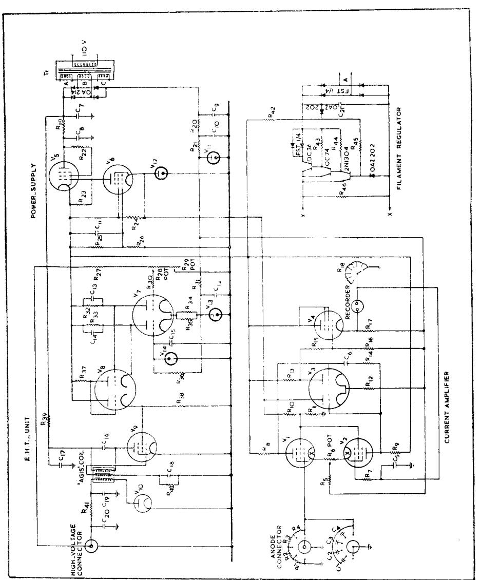
Fig. 4. The circuit-diagram.
good for photoelectric photometry were mainly used for testing the photometer, using only two colour filters: a blue filter of type BGl2 * GGl3 and a yellow filter of type GGll. Only well determined standard stars not too far from the equator were observed. At the end of the dry season a start was made with observations in order to determine the atmospheric extinction at Lembang.
8. ACKNOWLEDGEMENTS
The construction of the high voltage supply and the d.c.-amplifier which form the important parts of the photoelectric instrument, rvas achieved through grants awarded by the Australian Nationai University Canberra, Australia. I would like to express my sincere thanks for these grants.
I am mucl"L indebted to D'r's. B.J. Bok, S.C.B. Gascoigne, B. Westerlund and J. Whiteoak for their advice-
I am also indebted to the staff members of the electronic shoo of the Mount Slromlo Obselvatory for their great help and advice.
Also I would like to thank Drs. G.E. Kron, V.M. Blanco and R.J.H-Morris for their interest and generous help in this wolk.
I Iike to thank Mi'. Sutia of tl'-e worksi'Lop at the Bosscha Observatory for hjs great help in designing the photometerhead.
I also like to thank P.N. Ralin Bandung foi the construction of a stabilised higir voltage suppliel to be used witir an Ellll-type multiplier.
To the Colombo Plan I er^press rny sincele gratitude for the schola-r'ship.
10. REFFRENCES
- 1. Eggen, Clin J., A,p. J., 1i1.
- 2. Cooke, E.H., An Introciuction to Transisttrr Cilcuits, 1960.
- 3. Kron, Cerald, E., i{arvai'ci Circrilai, No. 45 1, 19,tr8.
- 4. Seely, Samuel, Election-Tulrc Cilcuits, Asiiin Studetlts Edition.
- 5. Vofiie, J., Annaleii v.ci. Bosscha Stcllenrvacirt, Vol. l, 1933.
List of components of the circuit for power- and high voltage supply.
| V Tubes | C Capacitors | R Resistors | R Resistors (continued) |
|---|---|---|---|
| 1 E80F | 1 470 pF 600V Styro seal | 1 1 Meg. | 23 .47 Meg. |
| 2 E80F | 2 .001 mF 600V ,, ,, | 2 9 Meg. | 24 39 K |
| 3 12AX7 | 3 .002 mF 600V " " | 3 90 Meg. | 25 100 K |
| 4 6AM6 | 4 .02 mF 200V ,, ,, | 4 900 Meg. | 26 68 K |
| 5 6BW6 | 5.01 mF | 5 100 K | \(27.3 \times 1\) Meg. |
| 6 E80F | 6 .01 mF | 6 3 K Helipot, | 28 100 K Pot. |
| 7 12AX7 | 7 16 mF el. filter cap. | 7 100 K | 29 .5 Meg. Pot. |
| 8 12AU7 | 8 16 mF " " " | 8 5.6 Meg. | 30 100 K |
| 9 6BW6 | 916 mF " " " | 9 5.6 Meg. | 31 3.9 K |
| 10 6X2 | 10 16 mF " " " | 10 100 K | 32 820 K |
| 11 0B2 | 11 .01 mF disc ceramic | 11 82 K | 33 820 K |
| 12 0B2 | 12 .01 mF ,, ,, | 12 75 K | 34 100 K |
| 13 0B2 | 13 .01 mF " " | 13 2 Meg. | 35 680 K |
| 14 85A2 | 14 .01 mF ,, ,, | 14 10 K | 36 15 K |
| 15 .01 mF ,, ,, | 15 4.7 Meg. | 37 2.7 Meg. | |
| Tr Transformer | 16 175 pF mica | 16 3.9 Meg. | 38 100 K |
| Tr H.T. Secondary | 17 .1 mF | 17 56 K | 39 4.7 K |
| 285 CT 285V | 18 .001 mF | 18 100, 58.5, 92.7, | 40 47 K |
| 60 MA | 19 .01 mF disc ceramic | 146.9, 232.9, 369, | 41 15 K |
| 12V at 1 Amp. | 20 .01 mF ,, ,, | 585, 927, 7488 ohm. | 42 100 K |
| 6.3V at 1 amp. | 21 2000 pF | 19 1 K | 43 220 ohm |
| 20 33 K | 44 3.3 K | ||
| "Agis" 2 KV R.F. coil | 21 27 K | 45 3.3 K | |
| 22 100 ohm | 46 68 ohm |