

Introduction
Cast iron machining particles (swarf) such as chips, borings or the like is a material which has apparently been proposed from time to time as a source of powder which can be pressed and sintered. The cost is also very low or nil if generated "in house". The swarf is first comminuted to a powder of suitable particle size. This is accomplished by milling and annealing cycle appropriate to the raw material.
This technique is now more preferred, since conventional techniques of remelting and casting of metal waste into ingot moulds may introduce undesirable pollution to the environment due to the burning of some lubricants retained in the chips. Also, accounting to energy savings as generally expected from Powder Metallurgy (P/M) technique, the use of powder metallurgical recycling technique is currently receiving much attention. Moreover, the recent oil crisis has if anything accentuated the need for further research in this field.
The use of the powder metallurgical recycling technique is not merely for the cast iron machining swarf, but it can also be recommended for other machining swarfs. For instance, it is only very recently that the Ford Motor Company's Engineering and Research Staff reported that Ford has developed a process for making iron powder from machining turnings. Researchers have made from chromium-nickel-molybdenum-silicon
alloy steel cnips—using a small pilot—set—up at Ford's Manufacturing Development Center—in Detroit. A large—pilot—line capable—of making—several thousand—pounds of powder monthly will be operating there by the end of 1978. The process—consists of cleaning the turnings, followed by shredding, embrittling, grinding, coating, annealing and then screening. It was also reported that powder can be made for approximately 65 per-cent of the current published per-pound price of atomized iron (1).
Chips of many materials especially brittle material such as cast iron can be recycled into powder easily. This is the main reason why the present work focuses only on the recycling of cast iron chips. In addition, wherever a great number of scraps and/or chips are found (e.g. in Indonesia), the use of this technique may be profitable.
Experimental procedures
a. Preparation of cast iron chips.
The cast iron chips were collected from the machining process. The grade of this cast iron was grey with a carbon content around \(3.5\,\%\). This cast iron was machined in dry condition on a lathe (turning) machine.
Powder preparation.
Of all the machining chips, cast iron chips are the most brittle and can easily be milled to very fine particles. The powder processing methods used include, swing hammer mill, eccentric grinding ball mill (conventional ball mill) and attrition mill. Table 1 presents the kinds of powder that have been processed.
c. Cold compaction.
The cylindrical specimens with a diameter of 10 mm were made by a hand press machine with an allowable compacting load of 7 ton. These specimens were prepared for the green density determination as a function of compacting pressure. Whereas the tensile test specimens were prepared by using a hydraulic press machine (maximum capacity: 100 ton). The tensile test specimens were made according to the MPIF standard with the pressure area: 1.0 sq-in.
d. Sintering.
After compacting, the green compacts of powdered cast iron chips were heated in a protective atmosphere furnace to a relatively high temperature, but below the melting point of the metal powder. Two sintering atmospheres used in this investigation were hydrogen \((\mathrm{H}_2)\) and argon \((\mathrm{Ar})\).
Table 1. Posders nade by different processing methads
| Poirder grades | Posder processing method |
|---|---|
| "l | Chips milled polrder into by sving haD[ler nill, |
| ^2 | Povder nilled further by eccentric \ grinding ball oill for 2 hours, |
| IdeD as A2 but with processing tioe 7 hours. | |
| Povder uas added vit}] 25 7" iron po',r \ der and Dixed for 1.5 hours iD Turbula lIElCnlne. | |
| - L | Powder fron chips r0ade by seiDg haEmer tDill lhen folloved b]' artririon ftillj-ng plocess for 7 hours. The resulting pow der r.ras annealed at 650oC for t hour un der hydrogen atnosphere. |
| - 2 | Powder BL r.ras added with l0 Z iron pow der and rDixed for 1.5 hours in Turbula nachine, |
| lden as B, but vith iron powder addition of25Z |
Note: A and B are grey cast iron with phosphorus content around 0.8 Z and O.7 Z resDectivelv.
Density measurexoent.
Green and sintered densities of the speci-rEn were measured by the Archimedean dethod.
Tensile test.
Tensi].e tests were carried ollt to heasure tensLle streDgth using an Instron Eachine,
Metallography. s.
Af1 speci.Dens vere exanined by light nicroscope after being pollshed and etched. The etchanr used for this grey cast iron !ras: nital (2 cc HN03 in 100 cc nethylalcohol). In palticular cases, the observatl-on of unetched specimen $ras oecessa ry.
The characteristics of a powder particle e.g. slze, shape, surface structure and pore detai.l lrere obtalned by using a Scanning Electron Microscope (SEM).
ErperineaLaL v,esul ts a<C dLsct^sstons
a. l'laterial-, chips and ponder.
The Daterial was grey cast iron vith two different grades of phosphorus contenl, one at + 0.8 Z and the other ac + 0,1 Z. The oricrostluctures are given in figure 1.
The chj-ps Eade from machining turnings show dlscontinuity due to the brittle propercies of cast irr.n (see figlrre 2).
The powder obrained from the chips was processed by different procedures as specified in Table 1 and the norphology of Ehe powder related to the process are presented in figure 3,
b . Conpacttbility.
As indj-cated j-n figure 3, the partlcles form should reflect to their compactibillties, As usual, the powder particles r.rith irregular shape should permit good particle interlocking during compacting co provide high green strengch. The density gain r.rith increasLng coDpactiDg pressure for lhese powders are sho\^rn in figures 4 and 5 for different condltions. Here, it shor.rtd be noted that the density of povder Al + A3 is lover then powders B for the saDe compacting pressure. This is due to the fact that the inherent free calbon of the loose graphite of cast iron powder acts as a Lubricant for compacti.on vhich provides high green density.
c. Sintered strength.
ln lhe sintering process, the particles are bondiog togeLher vhich is deternined prlnarily by the three important paraDeEers i.e. sintering atmosphere, temPeratule and tine, Hovever, the rate of bonding reaction that occurs during sintering could also be influenced by other mechanisms. Experlnental results given in figure 6 apparently show that hydrogen as sintering atmosphere gives a higher sintered strength then argon. ArId figure 6 describes that the increase in processing tlne of the cast iron powder by the S,rindinB ba]l milI lowers the tensile strength of the sinte(ed product. Furcher:r let us consider figure 6 as f o11ows r
- lf Lhe powdered casc iron chips is only produced by swing harbner mill, che r:esultirrg particles are irregular or Dodular in shape wliiclt permits good particle inter-
Fig. 1: Grey cast iron
- Fig. la: Grey cast iron of material for powder A. The graphite feature is rossete grouping type.
- Fig. 1b: Grey cast iron of material for powder 3. The graphite flake is uniform distributed on the whole matrix but with random orientation. (Unetched specimens)
- Fig. lc: Grey cast iron with graphite rossete groupings. The microstructure shows pearlite and territe. The white structure with small holes is a eutectic structure of iron phosphide and territe, called steadite. (light nital etch)
- Fig. ld: The matrix structure is almost completely pearlitic, although a few ferrite areas are visible with silicon, etc., in solid solution. (light nital etch)
Fig. 2: Configuration of grey cast iron chips
Fig. 3: Powder cast iron chips
Fig. 3: Powder cast iron chips.
- 3a: Grey cast iron powders made by swing hammer mill \((Powder A_1)\).
- 3b: Powder \(A_1\), after further processing on grinding ball mill for 2 hours (Powder \(A_2\)).
- 3c: Chips milled into powder by swing hammer mill, then continued by attrition milling process for 7 hours.
- 3d: As in fig. 3c, but at higher magnification.
- 3e: The resulting powder (as in fig. 3c) was annealed at 650°C for 1 hour under hydrogen atmosphere. Then the annealed powder was mixed with 10% iron powder.
- 3f: Scanning electron micrograph of powder A<sub>1</sub> (made by swing hammer milling technique).
- 3g: Scanning electron micrograph of powder B<sub>1</sub> (see Table 1).
locking during compacting and provides higher green and sintered strength.
- By processing further with the grinding ball mill the particle size decreases which can be followed by shredding of the lamellae graphite from their matrix to become inherent free carbon. The amount of this free carbon is sufficient to gain the compactibility, especially for lower compacting pressure (figure 4). But after the compacting pressure exceeds a value of 7.5 ton/cm², the green density of powder made from the swing hammer mill (powder A<sub>1</sub>) improves favourably and provides a higher green density of the compact. The restriction of sintering reaction of the compacts of powders of A<sub>2</sub> and A<sub>3</sub> might also be affected by the surface stresses that occur on the primary particles during further grinding process.
- Hydrogen can reduce the iron oxide and improves the sintering reaction, whereas argon only acts to prevent the oxidation during sintering. Argon chemically acts to promote graphitization whereas hydrogen seems to stabilize carbides. This is another reason why argon as sintering atmosphere provides lower sintered strength than hydrogen. The microstructures of sintered specimens are presented in figure 7.
The powder which was processed by the swing hammer mill followed by attrition milling exhibits a very green strength. This was caused by the excessive amount of loose graphite and iron oxide present in the powder. The annealing treatment was performed for this powder at 650°C for 1 hour under hydrogen atmosphere. It was possible to handle the compacts after annealing and surprisingly they show higher green density than the compacts of powders A. But the tensile strength of sintered specimens of powders B are much lower than the sintered strength of specimens from powders A as shown in figure 8. By the addition of 25 % iron powder, the sintered strength increases up to 11.62 kg/mm2. The microstructures of the sintered specimens of powder B are given in figure 9. From figure 9, it becomes clear that the excess of inherent free carbon present in the powder causes an interlinked network of fine graphite lamellae and this is one of the reasons why the material is weak.
A recent paper \(^{(2)}\) shows that the tensile strength of sintered cast iron specimen is apparently very much sensitive to an increase in the sintering temperature. For instance, a green compact of 8 ton/cm<sup>2</sup> compacting pressure, sintered at \(1100^{\circ}\)C for 1 hour under hydrogen atmosphere
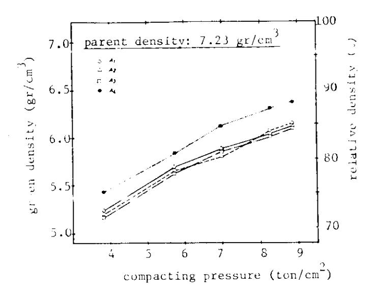
ig. 4: Green density vs compacting pressure (Powders A)
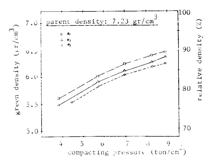
Fig. 5: Green density vs compacting pressure (Powders B)
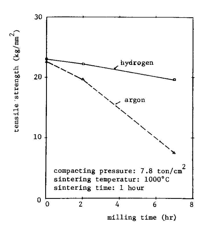
Fig. 6: Tensile strength of sintered specimens as a function of milling time (Powder A).
Fig. 7
Fig. 7a: Sintered specimen of powder \(^{\Lambda}_{1}\) (7.8 ton/cm\(^{2}\), \(^{1}_{2}\), 1000°C - 1 hour).
Fig. 7b: Sintered specimen of powder \(A_1\) (7.8 ton/cm<sup>2</sup>, Argon, \(1000^{\circ}\text{C} - 1 \text{ hour}\)).
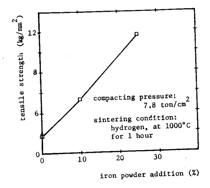
Fig. 8: Tensile strength of sintered specimens made from powders B as a function of per-cent iron powder addition.
Fig. 9 : Sintered specimens of powders B (7.8 ton/cm\(^2\), H\(_2\), 1000°C - 1 hour).
9a: Powder \(B_1\)9b: Powder \(B_2\)9c: Powder \(B_3\)
Fig. 10: Microstructure of sintered specimen (7.8 ton/cm\(^2\), \(\rm H_2\), 1100°C - 1 hour).
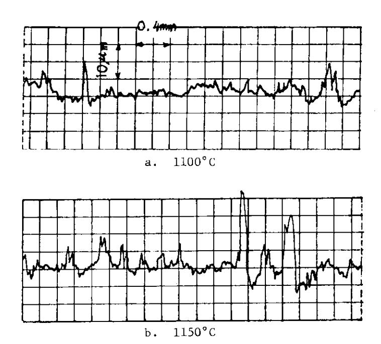
Fig. 11: Surface roughness of sintered specimen (7.8 ton/cm\(^2\), \(\rm H_2\)).
has provided up to 35 kg/mm<sup>2</sup> of tensile strength. It is also clear that the tensile strength is higher than the parent cast iron at sintering temperature above 1100°C even though the sintered specimens are porous. This may be because of a more homogeneous structure due to crushing and because the temperature of sintering is close to the melting point which may cause a transformation of flaked graphite into spheroidal shape as shown in figure 10 of the present work.
It was also noted that the sintering temperature however, has a limitation because higher sintering temperature increases the surface roughness of the product as shown in figure 11.
Conclusions
It has been shown that the powdered cast iron chips produced by using only swing hammer milling technique provides a higher sintered strength than the combination of a swing hammer and a grinding ball mill or an attrition mill. Thus, it can be applied in practice for making mechanical sintered parts with good quality and in an economical way. Cast iron turnings can be recycled into useful components by powder metallurgical technique, but it can also serve as a new base powder for the production of new materials.
In principle, further improvement could be expected if the particle size is further reduced. However, the finer the particles of cast iron powder, the greater the tendency of the graphite to be present as free flakes which then tends to decrease the tensile strength of the sintered parts. So, this does not offer advantages either mechanically or economically. However, if this problem is solved by removing the free carbon from the powder, there will be a still greater advantage of introduction of P/M recycling of cast iron chips.
Acknowledgement
The author whishes to thank Prof.Dr. E. Aernoudt for valuable discussions in this work and for permission to publish this paper.