

I THE BASIC CONCEPT OF THE SYSTEM
The rocket is launched from Cilauteureun launching station, and flies along the coast of Java Island to the eastern direction. Prior to launch, the launcher directions and angles are set to give the desired impact point, with adjustments to correct for the wind effects. (The vehicle is unguided during the flight and so tends to deviate to the north because of the crosswind).
The first motor stage burns for about 15 seconds. The empty motor case then falls into the sea about 5 km in front of the launcher.
At 16 seconds the main stage motor is ignited automatically by a timer and burns for about 26 seconds.
At 125 seconds and about 150 km altitude the playload and empty main stage motor case are separated and both follow a ballistic trajectory.
THE KAPPA - 8 ROCKET
At 160 seconds and about 170 km altitude the attitude control unit switches on and nitrogen gas jets operate, the payload pointing downwards to the targetted agricultural land. Gas jet corrections continue to maintain this attitude while the playload is in free space.
At 290 seconds and 170 km altitude the camera is exposed, photographing an area on the island. The payload is then turn in the horizontal position. It takes about 12 seconds. The payload re-enters the atmosphere in this position to enlarge the body cross section.
At about 400 seconds and 30 km altitude, the parachute is deployed and the payload takes about 100 minutes to descent at a rate of 5 m/second.
The Rawin Sonde tracking receiver is located on a distance of 100 km from the line of horizontal trajectory. The other Rawin Sonde receiver used for recovery aid is located near to the impact point so that the signal attenuation due to the diffraction, reffraction and transmision loss can be minimized.
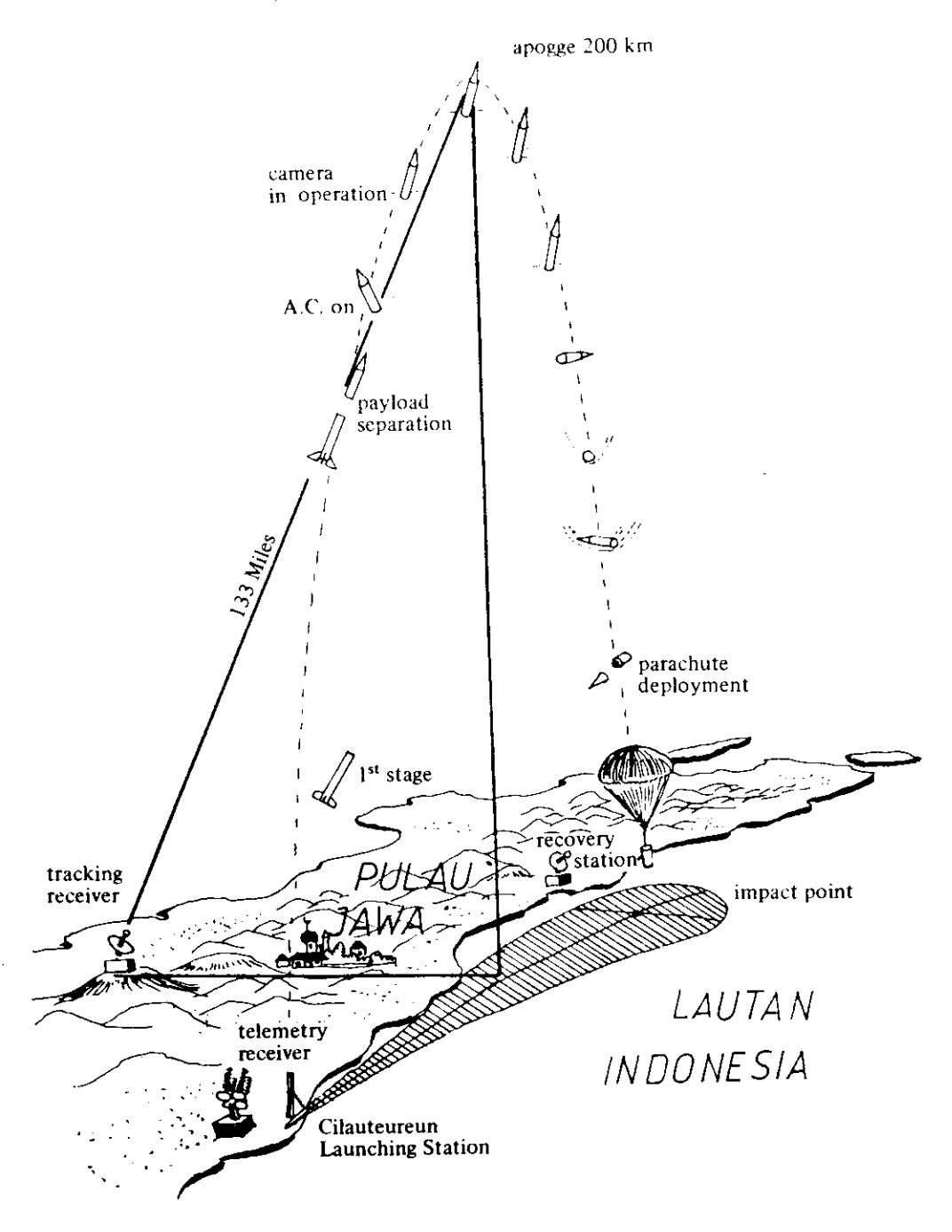
Figure 1 The basic concept
II. AIRBORNE SUBSYSTEM
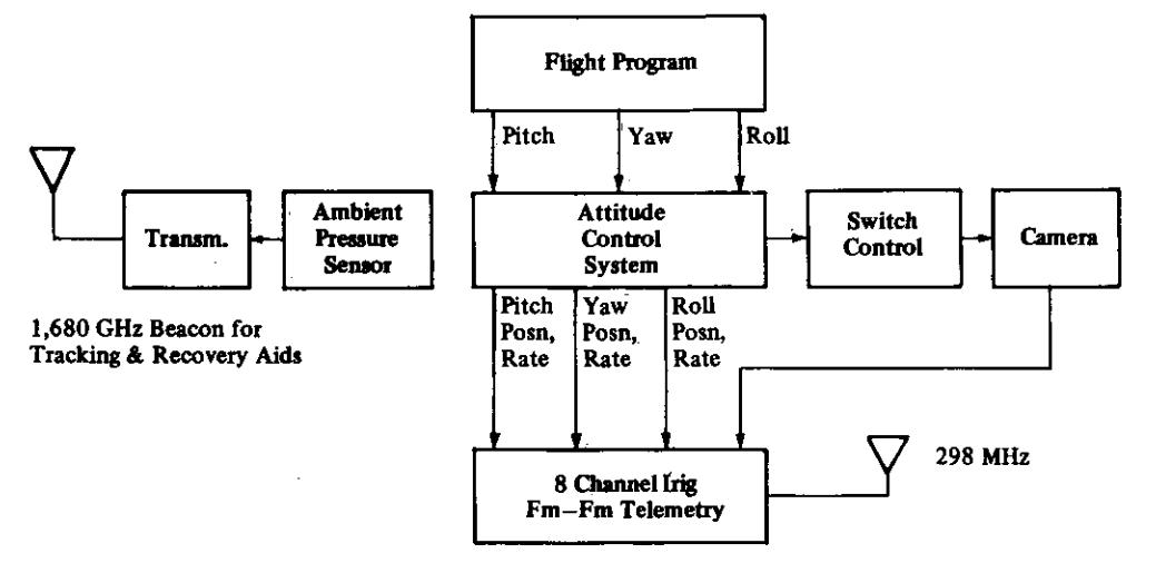
A schematic diagram of the payload is shown in figure 4. The main components are the attitude control unit, the flight programmer, the telemetry unit, the camera unit and the recovery bay.
a. The Attitude Control Unit
Consists of the pneumatic unit, gyro platfrom and the electronic control circuit. Located in the middle of the vehicle, give 0,5 m radius of action in the lateral axis. The vehicle dynamics is detected by the gyroscope in each axis which gives the error signal to the electronic control circuit. The control circuit then drives the pneumatic unit for correcting the vehicle orientation.
Figure 2 The airborne subsystem layout
Airborne Subsystem
Ground Subsystem
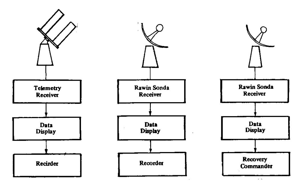
Figure 3 Block Diagram of the System
Figure 4 The payload assembly
b. Pneumatic Unit
The pneumatic unit contains a high pressure gas bottle within which three valve assemblies are mounted for controlling the release of the gas to the control jet which is located on the skin of the bay. Misalignment of the vehicle is detected by electronic control system with the result that signals for appropriate operation of the nozzle driver are fed from the attitude control bay to the pneumatic unit. Each nozzle driver control the release of the gas to the jets giving control about the appropriate axis.
1. Recovery Aids
The 1,680 Ghz amplitude modulation transmission for the payload gives the altitude, azimuth and the elevation in the Rawin Sonde receiver to assist payload location.
In visible sight, the payload can be easily seen by using the smoke generator.
III GROUND SUBSYSTEM
Consists of three receiver stations which are located in three different areas: The telemetry receiver is located in the launching station, the Rawin Sonde receiver for tracking is located at a distance of 100 km from the beach in the middle of the horizontal trajectory and the remaining one which is used for recovery aid, is located near to the impact point.
The telemetry station is already available in the Cilauteureun launching station. Manufactured by Nippon Electric Company, it consists of 4 helical array antenna with 18 DB gain, low noise receiver, discriminator, bandpass filter, frequency to voltage converter and data recorder.
IV. PAYLOAD MANOEUVRE GROUND TESTING
The required dynamics of the vehicle in free space during the flight can be adjusted on the ground by using low torque hydraulic bearing for the dynamic test and by simulating the vehicle dynamic into electronics circuit for the static test.
c. Control Jets
There are eight jets of which four are for lateral control and four are for roll control. Each of the four lateral control jets consists of a ventury arrangement so that each axis points radially outwards. The two jets providing control about the Z axis are located diametrically opposite to the Y axis and the two jets providing control about the Y axis are similarly diametrically opposed to the Z axis. The four roll jets are located next to the lateral Z jets so that the venturi axes are tangential to the skin of the pneumatic bay.
Rotation about a lateral control axis is effected by the release of the gas
through appropriate single venturi depending on the sense of rotation. Whereas rotation about the roll axis is effected by the release of the gas through the appropriate pair of roll jets venturies which are diametrically opposed and produce a couple.
d. The Valve
Figure 5 shows the basic construction of the valve. Pulse current is fed in the solenoid driving the pintle. The spring force which work on the pintle can be adjusted depending on the intlet pressure.
Figure 5 Basic Construction of the Solenoid Valve
e. The Control Circuit
The gyroscope provides position error signal for each axis, each signal being filtered for eliminating the noise spectrum and fed to the DC amplifier which gives the position signal and the phase advance circuit of the form \((K_1 \, S/K_2 \, S+1)\) giving the mayor damping term. The summation of the rate and the position signal provides the error signal. For the lateral control this signal is to be inverted. The positive error and the negative error then fed to the sine-cosine resolver giving the pulse modulator input. The pulse modulator determine the frequency and width to give the required control of the vehicle about the appropriate axis. The pulse width and repetition each vary nonlinearly with the input to the pulse modulator. By increasing the input, the pulse repetition frequency rises to maximum and then falls to zero at saturation, while the pulse width starts at a minimum value and rises parabolically to infinity at saturation.
f. Manoeuvre Programmer
More than one heading targets can be DC amplifier in the control module in timer. managed by giving various offsets to the each axis. TIrc sclcctor is controlledbya
g. Camera Installation
The Hasselblad 70 mm has been selected which has the ad vantages of being easy to install, high reliability, low cost and has a range of modern high performance lenses available.
l. Camera Switch Control
The limit cycle amplitude causes the payload oscillation in each axis. The small fraction of limit cycle amplitude has a great effect on the picture resolution. For example when the noise (limit cycle) amplitude is 10.25" for 200 km altitude, the amplitude on the earth surface will be 1750 m. For the higher altitude, the noise amplitude has to be reduced to get a better picture resolution. It can only be done by modifying the pneumatic unitx.
The other way to improve the picture resolution is by controlling the camera switch. During the period of limit cycle the payload periodically has a minimum rate in each axis, this point is detected by the logic circuit for controlling the camera, so that the camera switch on by the time the vehicle is almost ! um pletely steady.
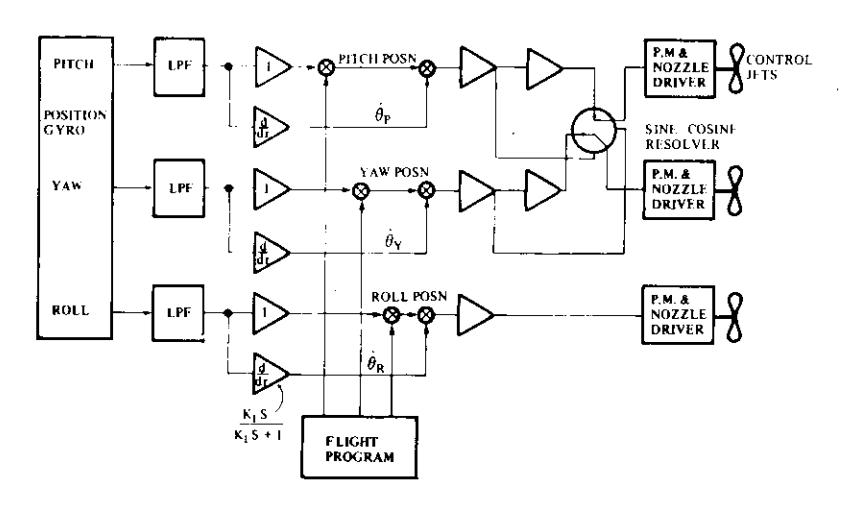
Figure 6 Block Diagram of the Control System
*Thc pncumatic unit manulactured by Space Vector (bmpany using tbc \olcnoi(l vrlve has the disad' vantage of slow operation (approx. 20 miliscc. ) . It is recomnrcn(lcd. houcvcr bccause of its sinple mechanical stlucture and low cost.
Figure 7 The attitude control bay \(^{@}\) (photopgraph courtesy of John J. Turn\(\epsilon^{-1}\)
Figure 8 The solenoid valve®
<sup>®</sup>Manufactured by Space Vector Company.
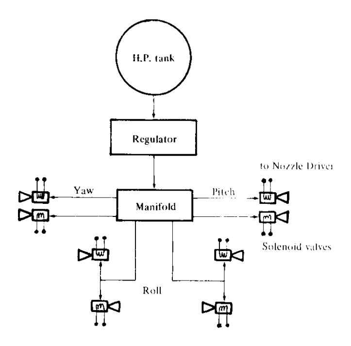
Figure 9 Schematic Diagram of the Pneumatic Unit
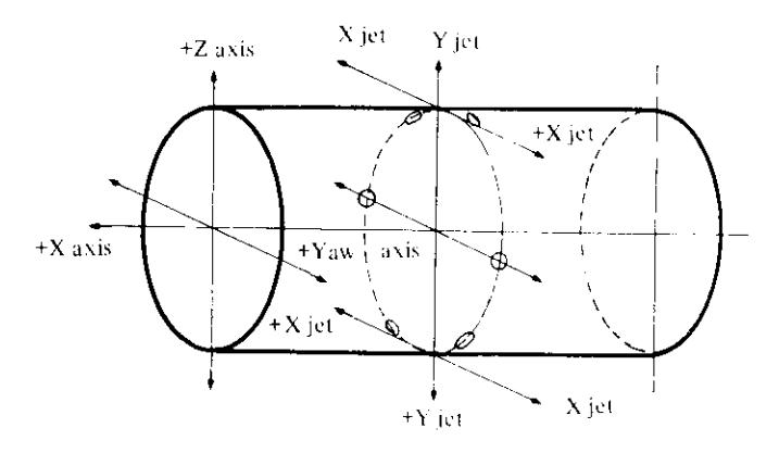
Figure 10 Jet Location Arrangement
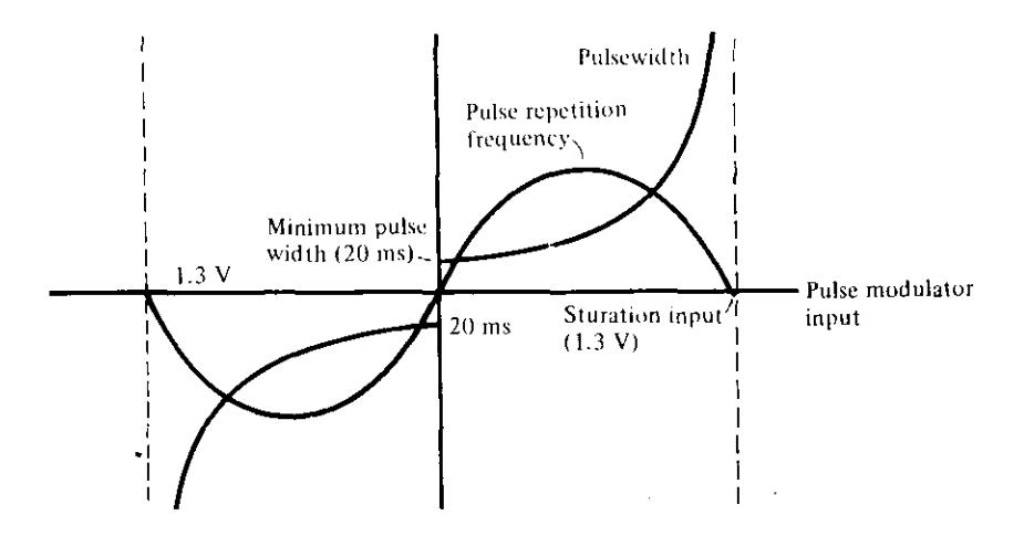
Figure 11 Pulse Modulator Characteristics
h. Airbome Telemetry
The FDM-FM airborne telemetry can be developed by LAPAN and consists of the voltage control oscillators, the active bandpass filters, a multiplexer and a FM transmitter with the RF power output of 1.5 watt & frequency center 298 MHz. The dipole hook type antenna with -6 db gain (referred to as isotropic antenna) is mounted on the skin of the telemetry bay.
Table 1 Airborne Telemetry Channel
| Parameter | IRIG+ Channel number | ||
|---|---|---|---|
| Yaw position | 10 | ||
| Yaw rate | 9 | ||
| Pitch position | 8 | ||
| Pitch rate | 7 | ||
| Roll position | 6 | ||
| Roll rate | 5 | ||
| Camera on-off | 4 | ||
| Payload separation | 3 | ||
<sup>+</sup> Inter Range Instrumentation Group.
i. Recovery Unit
Two types of water recovery systems can be developed by LAPAN with the assistance of a DFVLR specialist in the context of the operation between LAPAN-DFVLR. One uses the ram-air inflated balloon which is fitted in the top of the parachute and the other uses an inflatable flotation collar.
Figure 12 The Water Recovery Parachute Developed by the German Space Agency (DFVLR)
IV.1. The Static Testing Under Simulated Flight Condition
A block diagram of the vechile dynamics simulator is shown in figure 14. Actually, the gyroscope detects the vehicle orientation giving the position error signal to the control module. It consists of buffer & limiter 1st integrator, 2nd integrator equilizing the vehicle characteristic moment, angular velocity and position.
The position signal is equal to the gyroscope output fed to the control module. The vehicle movements for the initial position to the target then can be optimized by adjusting the rate amplifier gain or the loop gain in the control module.
IV.2. The Dynamic Testing Under Simulated Flight Condition
The test vehicle consisting of the basic test round and the low torque bearing has a fixed characteristic moment. The requirement is to use this vehicle to represent around of given flight characteristic moment. This is achieved by adjusting the pressure of the nitrogen in the low pressure regulated jet manifold. In this way the test vehicle will reproduce the flight acceleration of the flight vehicle.
The nominal pressure for flight is about 5 bar, the working pressure is given by:
\[P_{w} = (5CM_{t}/CM_{f}) + 1\]
Where: \(CM_t\) – The characteristic moment of the test vehicle. \(CM_f\) – The flight characteristic moment.
The characteristic moment of the vehicle can be measured by using the single axis air bearing following the formula:
CM = \[r_b (r_b + r_s) mgt^2 / 4\pi^2 r_s r_j\]
Where: \(r_b, r_s\) — meter
\(t\) — in second (time for one socillation)
\(m\) — in kg (mass of the pendulum)
\(g\) — in \(m/s^2\) (constant of gravitation)
\(r_j\) — in meter (radius of action of the jet)
Tabel 2
| IRIG Channel Number | Channel Center Freq (Hz) | Deviation | Low Band Edge (Hz) | High Band Edge (Hz) | Data Cutoff Freq (Hz |
|---|---|---|---|---|---|
| 1 | 400 | ± 7.5% | 370 | 430 | 6 |
| 2 | 560 | ± 7.5% | 518 | 602 | 8 |
| 3 | 730 | ± 7.5% | 675 | 785 | 11 |
| 4 | 960 | ± 7.5% | 888 | 1,032 | 14 |
| 5 | 1,300 | ± 7.5% | 1,202 | 1,398 | 20 |
| 6 | 1,700 | ± 7.5% | 1,572 | 1,828 | 25 |
| 7 | 2,300 | ± 7.5% | 2,127 | 2,473 | 35 |
| 8 | 3,000 | ± 7.5% | 2,775 | 3,225 | 45 |
| 9 | 3,900 | ± 7.5% | 3,607 | 4,193 | 59 |
| 10 | 5,400 | ± 7.5% | 3,607 | 4,193 | 81 |
| 11 | 7,350 | ± 7.5% | 6,799 | 7,901 | 110 |
| 12 | 10,500 | ± 7.5% | 9,712 | 11,288 | 160 |
| 13 | 14,500 | ± 7.5% | 13,412 | 15,588 | 220 |
| 14 | 22,000 | ±7.5% | 20,350 | 23,650 | 330 |
| 15 | 30,000 | ±7.5% | 27,750 | 32,250 | 450 |
| 16 | 40,000 | ±7.5% | 37,000 | 43,000 | 600 |
| 17 | 52,500 | ±7.5% | 48,562 | 56,438 | 790 |
| 18 | 70,000 | ±7.5% | 64,750 | 75,250 | 1050 |
| 19 | 93,000 | ±7.5% | 86,025 | 99,975 | 1395 |
| 20 | 124,000 | ±7.5% | 114,700 | 133,300 | 1860 |
| 21 | 165,000 | ± 7.5% | 152,625 | 177,375 | 2475 |
| Α | 22,000 | ±15 % | 18,700 | 25,300 | 660 |
| В | 30,000 | ±15 % | 25,500 | 34,500 | 900 |
| C | 40,000 | ±15 % | 34,000 | 46,000 | 1200 |
| D | 52,500 | ±15 % | 44,625 | 60,375 | 1575 |
| E | 70,000 | ±15 % | 59,500 | 80,500 | 2100 |
| F | 93,000 | ±15 % | 79,050 | 106,950 | 2790 |
| G | 124,000 | ±15 % | 105,400 | 142,600 | 3720 |
| Ħ | 165,000 | ±15 % | 140.250 | 189,750 | 4950 |
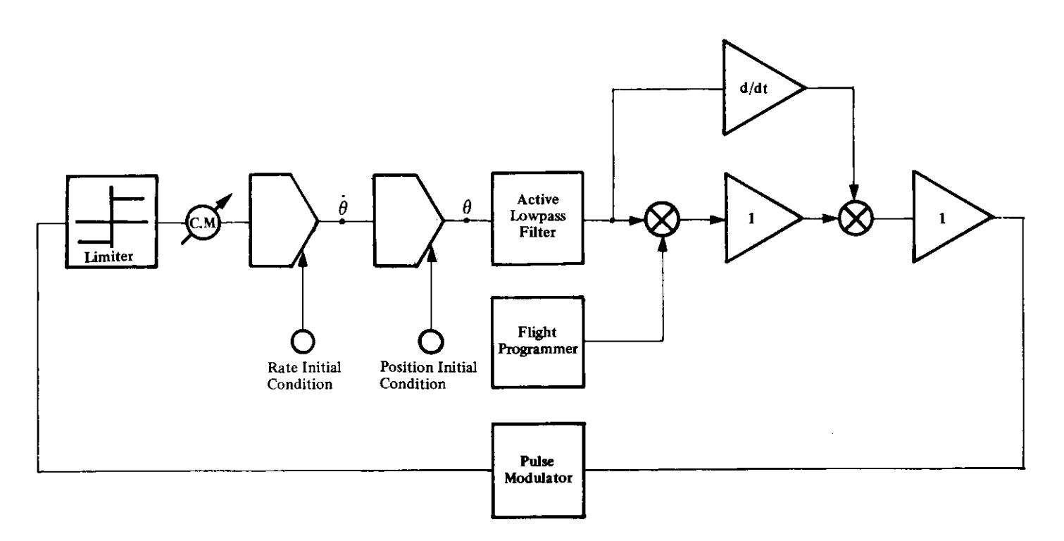
Figure 13 Block Diagram of the Simulator
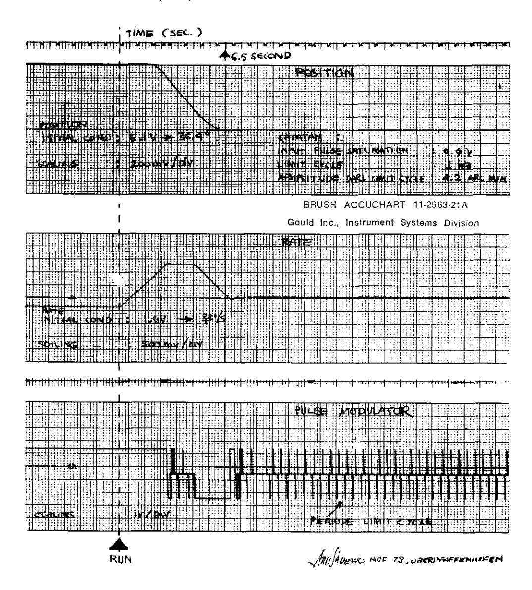
Figure 14 Curves obtained from the simulator showing the vehicle motion in the lateral axis. The acquisition time is 6.5 seconds with only 2% overshoot.
Figure 15 Single Axis Air Bearing Manufactured by Marcony Ltd.
The Payload Dynamics Simulator
Figue 17 Pulse Modulator & Nozzle Driver
Figure 18 Calculating characteristic moment of the vehicle on the low torque air bearing
V. EXPECTED PERFORMANCE
The heading accuracy of the vehicle is the important requirement in the attitude control payload design.
The error of the control system reference coordinate with respect to the target coordinates is defined as the pointing error. For each control axis it can be expressed as bias, drift and noise. Where it may be explained as:
Bias : The ordinate of the line at the completion of inital stabilisation.
Drift: The slope of the line (a function of operation time).
Noise : The deviation from the straight line.
V.I. Performance Detail
| Total weight of the payload | : 83 kg |
|---|---|
| Lateral characteristic moment | : 49.03 kgm |
| Roll characteristic moment | : 4.96 kgm |
| Lateral jet thrust | : 2.94 N |
| Roll jet thrust (each) | : 1.45 N |
| Minimum pulse width | : 20 millisec. |
| The second second second second second second second second second second second second second second second second second second second second second second second second second second second second second second second second second second second second second second second second second second second second second second second second second second second second second second second second second second second second second second second second second second second second second second second second second second second second second second second second second second second second second second second second second second second second second second second second second second second second second second second second second second second second second second second second second second second second second second second second second second second second second second second second second second second second second second second second second second second second second second second second second second second second second second second second second second second second second second second second second second second second second second second second second second second second second second second second second second second second second second second second second second second second second second second second second second second second second second second second second second second second second second second second second second second second second second second second second second second second second second second second second second second second second second second second second second second second second second second second second second second second second second second second second second second second second second second second second second second second second second second second second second second second second second second second second second second second second second second second second second second second second second second second second second second secon |
Maximum angular velocities at control inception for roll and lateral axis : 20°/sec.
Maximum acceleration when the valve saturated for roll axis : 0.6 rad/sec.<sup>2</sup> lateral axis : 0.06 rad/sec.<sup>2</sup>
| Axis | Bias | Drift | Noise | Pointing Error |
|---|---|---|---|---|
| Pitch | ± 2° | 0.1°/min. | ±0.16° | \((2.00 \pm 0.16)^{\circ}\) |
| Yaw | ± 2° | 0.1°/min. | ±0.16° | \((2.00 \pm 0.16)^{\circ}\) |
| Roll | ± 2° | 0.1°/min. | ±0.5° | \((2.0 \pm 0.5)^{\circ}\) |
VI. CONCLUSION
The Static test under simulated flight condition in the analog computer give reasonable results of the vehicle motion and heading accuracy for the earth surface pointing purpose.
The pointing error can be improved by using the high speed valve in the pneumatic section and using the sun for fine mode reference in the control system, however, their complexity and cost are correspondingly higher.
VII. ACKNOWLEDGEMENT
The author would like to express his appreciation to Dr. K. Schmidt of the German Space Operation Center (GSOC) - System Technic and the staff of the GSOC - Mobile Rocket Base (MORABA) in general for the opportunity to take part in the balloon and rocket activity during the training programme in DFVLR - Oberpfaffenhofen.
The author would also like to thank the following: John J. Turner, John How, Echkart Krieg, Peter Turner and Natarajan for their valuable advices during the preparation of this paper.
(Ich danke Herrn Dr. K. Schmidt von der GSOC System Technik sowie der Mobile Raketen Basis Belegschaft für die gute Zusammenarbeit und die Möglichkeit, dass ich während meines Training aufenthaltes bei der DFVLR an Balloon – und Raketenexperimenten teilnehmen konnte.
Mein Dank gilt ebenso d'e Herren John J. Turner, John How, Echkart Krieg, Peter Turner und Natarajan für ihre wertvoll Gutachtens bei der Ausarbeitung dieses Papiers).
VIII REFERENCES
- A.S. Korovin (translator), Spacecraft Control System, Translation of System Uprayleniva Kosmicheskikh Apparator, Military Press, Moscow, 1972, NASA Report no. NASA TT, F 774.
- Granino A. Korn, Ph.D. and Theresa M. Korn, M.S., Computers in Controls, Mc. Graw Hill Book Company, Inc. New York, 1969.
- John J. Furner, Telecommanded Inertially Referenced Attitude Control System, AIAA 4<sup>th</sup> Sounding Rocket Technology Conference, Boston, June 23 25, 1976.
- -----, A guide to Available Sounding Rocket Attitude Control System, DFVLR GSOC Mobile Raketen Basis, 1973,
- L.R. Bannister and C.A. Hookey, The Black Arrow Control System, Journal of the British Interplanetary Society, vol. 22, pp.91 122.
- Sugiharmadji HPS, Kuswadi, Roket-roket Kappa 8 dan RT-150, Loka Karya Peroketan LAPAN, Maret 29 April 1, 1976.
- V. Rajaraman, Analog Computation and Simulation, Prentice Hall of India, New delhi, 1977.
- W.R. Ahrendt and C.J. Savant Jr., Servo Mechanism Practice, Mc. Graw Hill Book Co., 1971.