

SARJ
Nitrida mangan, Mn<sub>4</sub>N telah diteliti dengan teknik difraksi neutron tak-terpolarisasi maupun terpolarisasi. Ternyata kedua refleksi, (100) dan (110), dapat menghasilkan hampir 100% neutron terpolarisasi serta monokromatik. Lebih lanjut diketahui bahwa kedua refleksi tersebut menghasilkan polarisasi yang berlawanan arah. Refleksi (100) hanya memantulkan neutron dengan polarisasi yang berlawanan arah dengan magnetisasi, sedangkan refleksi (110) menghasilkan neutron dengan polarisasi searah dengan magnetisasi. Hal ini membuka kemungkinan untuk memproduksi neutron monokromatik dengan salah satu keadaan polarisasi, dengan cara berpindah dari suatu refleksi ke refleksi lainnya tanpa menggunakan alat elektronik.
** Research Centre for Nuclear Techniques, Bandung
*** Bhabha Atomic Research Centre, Trombay, India
+ Since deceased
l. Introduction
The paucity of good polarizing monochromators in neutron spectrometry is well known. Cobalt, alloyed with iron to stabilise it in the fcc phase (Coo.r, Feoou ), is used most often in spite of its high absorption and poor reflectivity. More recently, Heusler alloy, Cu2 MnAl, has been developed as an alternative within the reach of several laboratories. But, because of its large cell constant, this crystal is suitable only when longer wavelengths are desired or as a polarization znaly zer.
Another candidate is FerSi which has similar characteristics 25 polarizeras thc Heusler alloy. Both materials fomr superlattices based on fcc structure and in each case the (l I l) reflection is matched. Since the nuclear scattering amplitude of the (222) reflection in both materials is significantly higher than that of (l I I ) it follows that the second order contamination can be a problem (Delapalme et al, 1971).
Iron is an alternative to Coo.rrFeo.or, since it has a similar d-spacing and a lower absorption. Natural iron has too large a nuclear scattering antplitude (b = 0.951 X lOl2cm), but Koehler, at the Oak Ridge National Laboratory, has made a single crystal of Fe mired with the isotope FesT (b = 0.23 x I Fr2 cm) and 3% Si which gives excellent polarization in the (I I0) reflection. Of course, such a monochromator is very costly and beyond the reach of most establishments.
Thus, any new possibility of a polarizing nlonocllromator is always a wclcome news in neutron spectrome trv.
In the course of our investigation on the magnetic structure and magnetic form factors in MnqN (Satya Mtffthy et al, 1985) we have observcd that the first two reflections, ( 100) and ( I I 0), present themselves as two very good candidates as neutron polarizing Bragg reflections. Furthermore, the two reflections provide opposite senses of polarization. This would then offer the very interesting possibility of producing polarized, monochromatic neutrons of either state of polarization by switching from one reflection to the olher, without the use of electronic fl ipping devices.
2. Experiment
2.1 Sample Preparation
Although Mn-N system was studied by a number of workers, the results on the preparation methods and phase diagram are still being modifired. In the literature, MnoN phase has been described by Hansen and Anderko (1958) as having a smaller range and decomposirg peritectically at a temperature of 700"C and above. The phase diagram published by Smithells (1976) shows a narrow composition range for the formation of the \(\epsilon\)-Mn<sub>4</sub>N phase and does not indicate the temperature range. However, in comparison to the Smithells' phase diagram, the modified diagram compiled by the General Electric Co. shows that \(\epsilon\)-Mn<sub>4</sub>N phase has a slightly broader composition range (Fig. 1).
The nitride was first prepared by Mah (1958) by heating manganese metal in a stream of nitrogen for 31 hours at \(900^{\circ}\text{C}-970^{\circ}\text{C}\). However, it was reported by Takei, Shirane, and Frazer (1960), that by following the method suggested by Mah, there was always a presence of \(\zeta\)-Mn<sub>2</sub>N phase and, to some extend, MnO. Hence, we have done a detailed study of manganese nitridation in the entire temperature range of \(400^{\circ}\text{C}\) to \(1000^{\circ}\text{C}\) to ascertain the optimum conditions for getting Mn<sub>4</sub>N devoid of other phases. One major problem encountered during our work was the surface oxidation at higher temperature, even after passing nitrogen through columns with copper turnings over Mn powder.
The schematic diagram of the apparatus used for the synthesis of Mn<sub>4</sub>N is shown in Fig. 2. Best results were obtained when nitrogen was passed through a column of titanium sponge kept at 600°C in addition to passing through columns packed with Cu turnigs. Nitrogen gas free of oxygen was passed into the reacting chamber containing pure manganese powder kept in a quartz boat at a temperature of 600°C for a period of 3 to 4 hours. It was found neccessary to crush the resulting product and repeat the heat treatment again a couple of times to ensure total reaction and to get rid of other possible phases.
The initial analysis was done by X-ray diffraction. It was found that the diffraction pattern did not reveal any other phases. An X-ray analysis of \(Mn_4N\) sample commercially available has also been performed for comparison. Fig. 3 shows the diffraction patterns of \(Mn_4N\) samples which has been purchased from the GOODFELLOW METALS INC., Cambridge, England (a) and the sample which has been prepared by method described above (b). The purchased sample shows the presence of \(\zeta\)-Mn<sub>2</sub>N and traces of MnO.
2.2 Neutron Diffraction Measurements
The unpolarized neutron diffraction measurements at room temperature were conducted at the TRIGA MARK II reactor of the Research Centre for Nuclear Techniques (PPTN/BATAN), Bandung, with a neutron wavelength of 1.07 Å. The \(\rm Mn_4\,N\) powder sample was put in a vanadium cylindrical tube of 1.6 cm \(\rm X\) 4 cm .
Polarized neutron diffraction patterns at room temperature were recorded using the polarized neutron spectrometer at the CIRUS reactor, Bhabha Atomic Research Center (BARC) at Trombay. This instrument has a \(Co_{0.92}\) \(Fe_{0.08}\) as a polarizing crystal with its (200) plane reflecting monochromatic (\(\lambda = 0.92\) Å), polarized (P = 97.5%) neutrons. The neutron spin flipper is a R.F. coil placed in a uniform magnetic guide field of \(1.1 \times 10^{-2}\) T and has a flipping efficiency of 99.9%. The flat sample was mounted on an electromagnet which provides a magnetic field up to 1.2 T in a gap of 18 mm.
3. Results and Discussion
Fig. 4 shows the powder diffraction patterns of \(Mn_4N\) at room temperature for neutrons polarized parallel (a) and antiparallel (b) to the magnetizing field. Unpolarized neutron data (c) is also shown for comparison.
Since the experimental conditions of both the polarized and unpolarized measurements were different - e.g. the wavelength and the sample shapes - hence it was necessary to modify the unpolarized diffraction pattern in accordance with the polarized neutron experimental conditions. This was done by converting the wavelength to \(\lambda = 0.92\) Å and the cylindrical sample to a flat sample.
The patterns show interesting features. For neutrons polarized parallel to the magnetizing field, the (100) reflection is absent, while (110) is a strong reflection; the reverse is the case when the neutron polarization is opposite to the magnetization. This can be explained as follows:
When the crystal is magnetized to saturation at right angle to the scattering vector, then,
\[I_{\pm} \alpha |F_{N}|^{2} + |F_{M}|^{2} + 2 F_{N} F_{M}\] (1)
here, \(I_+\) and \(I_-\) are the scattered intensities for the two spin states, whereas \(F_N\) and \(F_M\) are the nuclear and magnetic structure factors, respectively.
The polarization P is defined as
\[P = \frac{I_{+} - I_{-}}{I_{+} + I_{-}} = \frac{2 F_{N} F_{M}}{|F_{N}|^{2} + |F_{M}|^{2}}\] (2)
According to (2), if, for a particular reflection, \(F_N = F_M\), then the scattered beam will be completely polarized with polarization parallel to the magnetization direction. On the other hand, if, for a particular reflection, \(F_N = -F_M\), then the polarization of the beam is in the opposite direction to the magnetizing field.
Our previous measurements on \(Mn_4N\) (Satya Murthy et al, 1985) indicates that the crystal structure has a space group of Pm3m in which the Mn atoms form an fcc matrix and the nitrogen atom occupies the interstitial body centre position. The analysis of the unpolarized neutron diffraction profiles shows that the structure is ferrimagnetic with magnetic moments of \(\mu_I = 3.50 \ \mu_B\) and \(\mu_{II} = -0.89 \ \mu_B\)
for the corner and the face centre atoms, respectively.
For the (100) superlattice reflection,
\[F_{N} = -b_{N} \tag{3}\] and
\[F_{M} = r_{o} \gamma \left( \mu_{I} f_{I,100} - \mu_{II} f_{II,100} \right) \tag{4}\] where, as usual, \(b_N = 0.94 \times 10^{-12}\) cm is the nuclear scattering amplitude, \(r_o\) is the classical electron radius, \(\gamma\) is the magnetic moment of the neutron in nuclear magnetons, and \(f_I\) and \(f_{II}\) are the magnetic form factors of the corner and face centre atoms, respectively. By putting the values of \(f_I\) and \(f_{II}\) obtained from our previous experiment in (4) we get \(F_M = 0.88 \times 10^{-12}\) cm, hence substituting \(F_{II} = -0.94 \times 10^{-12}\) cm and \(F_M = 0.88 \times 10^{-12}\) cm into (2), the calculated polarizing efficiency will be \(P_{100} = 99.5\%\). Since \(F_N\) and \(F_M\) have opposite signs, the polarization of the reflecting beam is in the opposite direction to the magnetizing field.
The corresponding values for the (110) superlattice reflection are, \(F_N = b_N = 0.94 \times 10^{-12}\) cm and \(F_M = 0.70 \times 10^{-12}\) cm which yields a polarizing efficiency of \(P_{110} = 95.5\%\). The polarization is parallel to the magnetic field because both \(F_N\) and \(F_M\) have the same signs.
Table I compares the polarizing and reflecting characteristics of Mn<sub>4</sub>N with those of Co<sub>0.92</sub> Fe<sub>0.08</sub> and Cu<sub>2</sub>MnAl. The nuclear structure factors for both reflections in Mn<sub>4</sub>N arise only from scattering by nitrogen. This permits the possibility of substituting some carbon for nitrogen in order to improve the efficiency of the (110) reflection, if it is prefered because of its d-spacing. This, however, will worsen the efficiency of the (100) reflection. It is possible that a smaller substitution of manganese by iron will achieve very good polarizing efficiencies simultaneously for both (100) and (110) through the difference in the form factors. (This has, however to be confirmed by actual experimentation).
This would then offer the very interesting possibility of producing polarized, monochromatic neutrons of either state of polarization by switching from one reflection to the other, without using electronic flipping devices. It has to be recognised that the two reflections will provide different wavelengths for the same setting of the monochromator scattering angle. Both reflections have low second order contaminations. The absorption cross section of manganese may be considered to be within reasonable limits.
Unfortunately, single crystals of Mn<sub>4</sub>N have so far not been produced. It is
Table 1 Polarizing and reflecting characteristics of Mn<sub>4</sub>N compared to those of \(Co_{0.92}\,Fe_{0.08}\) and \(Cu_2\,MnA1\).
| Mn4 N | Co0,92 Fe0,08 | Cu2 MnAl | |
|---|---|---|---|
| Matched | (100) for ↓ | (200) | (111) |
| Reflection | (110) for ↑ | ||
| d – spacing | \(d_{100} = 3.87\) | 1.74 | 3.43 |
| (Å) | d110 = 2.74 | ||
| Polarization | \(P_{100} = 99.5\%\) | 94% | 99.8% |
| Efficiency (P) | P110 = 94.5% | ||
| Polarization | \(R_{100} = 0.002\) | 22.1 | 0.001 |
| Ratio (R) | \(R_{110} = 35.3\) | ||
| Crystallography | \(Q_{\perp}^{100} = 0.008\) | ||
| Quantity (Q) | \(Q_{-}^{100} = 3.27\) | \(Q_{+} = 3.14\) | \(Q_{+} = 0.003\) |
| \(\lambda = 0.92 \text{ Å}\) | \(Q_{+}^{110} = 1.85\) | Q_= 0.14 | Q_= 2.18 |
| \(Q_{-}^{110} = 0.05\) | |||
| Integrated | \({}^{+}R_{o}^{\theta}\) (100) = 0.02 | ||
| Reflection \((R_o^\theta)\) | \(^{-}R_{o}^{\theta}\) (100) = 0.48 | \({}^{+}R_{0}^{\theta} = 0.32\) | \(^{+}R_{0}^{\theta} = 0.0\) |
| \(^{+}R_{0}^{\theta}\) (110) = 0.30 | \(-R_{0}^{\theta} = 0.07\) | \(-R_0^{\theta} = 0.3\) | |
| \(-R_{o}^{\theta}\) (110) = 0.05 | v | J | |
| Integrated | 1, (100) = 0.008 | ||
| Intensity \((\vec{\epsilon}, \vec{K} = 0)\) | 1_(100) = 3.21 | I+ = 4.07 | 1_ = 0.03 |
| I+(110) = 2.59 | i_ = 0.18 | 1_ = 32.9 | |
| I_(110) = 0.07 | |||
| \(2\theta\) for 1Å neutrons | 2θ (100) = 14.9 | 33.1 | 16.7 |
| (degrees) | \(2\theta\) (110) = 21.1 | ||
| Maximum wavelength | λ (100) = 7.7 | 3.5 | 6.9 |
| (Å) | \(\lambda\) (110) = 5.5 |
hoped that this attractive possibility of new polarizing monochromator will spur new efforts in this direction.
4. References
- l. Delapalme, A., J. Schweizer, G. Couderchon, R. Perreir de la Bathie, Nucl Instrum. Meth., 95,589, l97l
- 2. Hansen, M. and K. Anderko, Cotlstitution of Binary .A//oys, Mc.Graw-Hill, 1958
- 3. Mah, A,.D.,J. Am. Chem. Soc.,80,2954, 1958
- 4. Satya Murthy, N. S., S. K. Paranjpe, Marsongkohadi, Kumiadi Sumaamidjaja, and M. R. L. N. M\rthy, hamanq 24, 3ll, 1985
- 5. Smithells, C.J.Metal ReJbrepce Book, ed.5, Butterworlh, 1976
- 6. Takei, W., G. Shirane, B. C. Fnzer, Phys. Rev., 1 19, 112, 1960
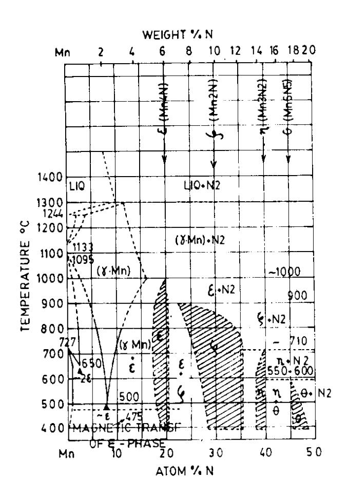
Fig, 1 Modified phase diagram of the Mn-N system compiled by the General Electric Co., showing the e-MnaN, f-MN2N, ?'Mn3N and d-Mn6N5 phases. l\4agnetic transformation occurs at 4750C.
Fig. 2 Schematic diagram of the apparatus for the synthesis of Mn<sub>4</sub>N.
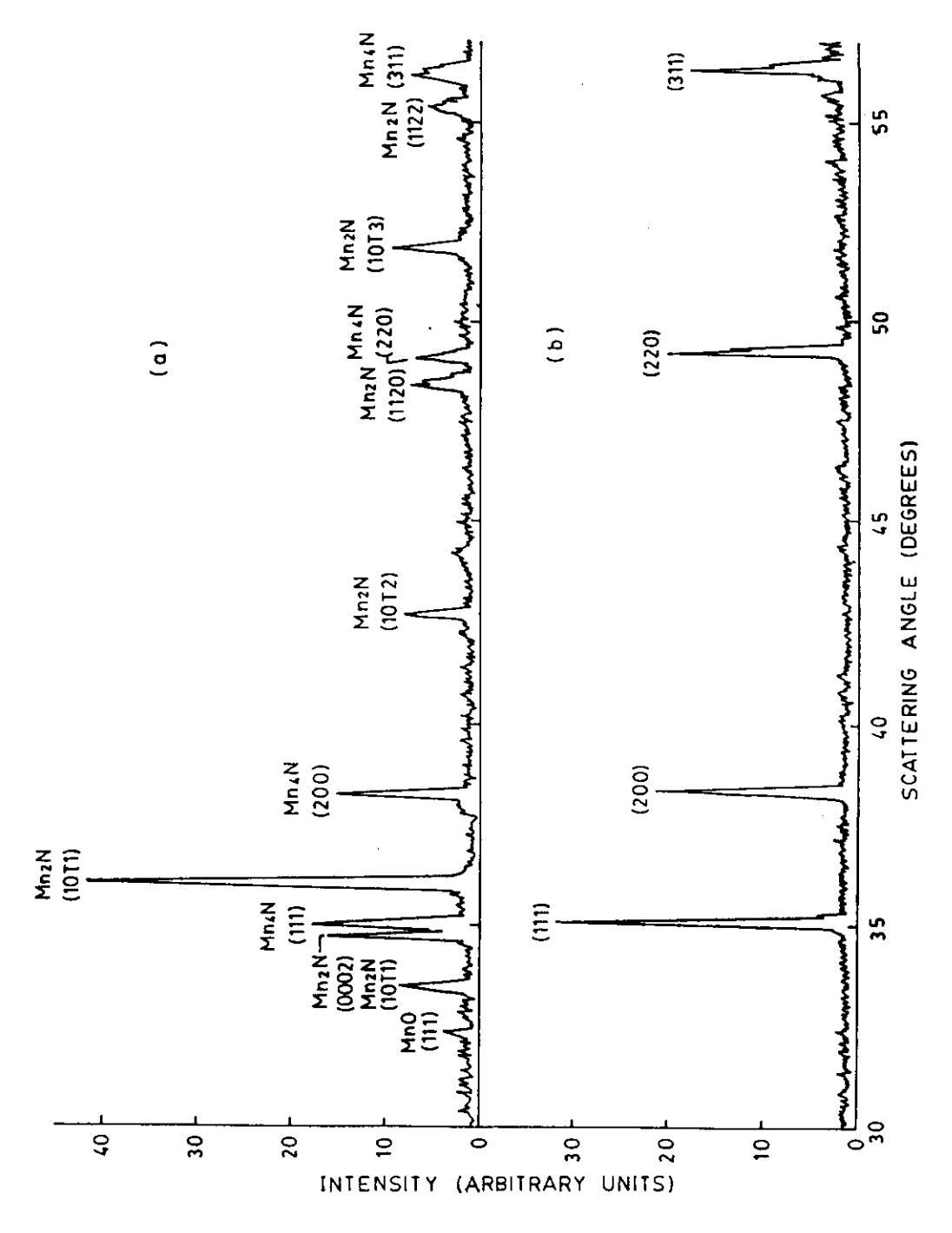
Fig. 3 X-ray diffraction patterns of \(Mn_4N\); for commercially available sample (a) and for \(Mn_4N\) sample used throughout this experiment (b).
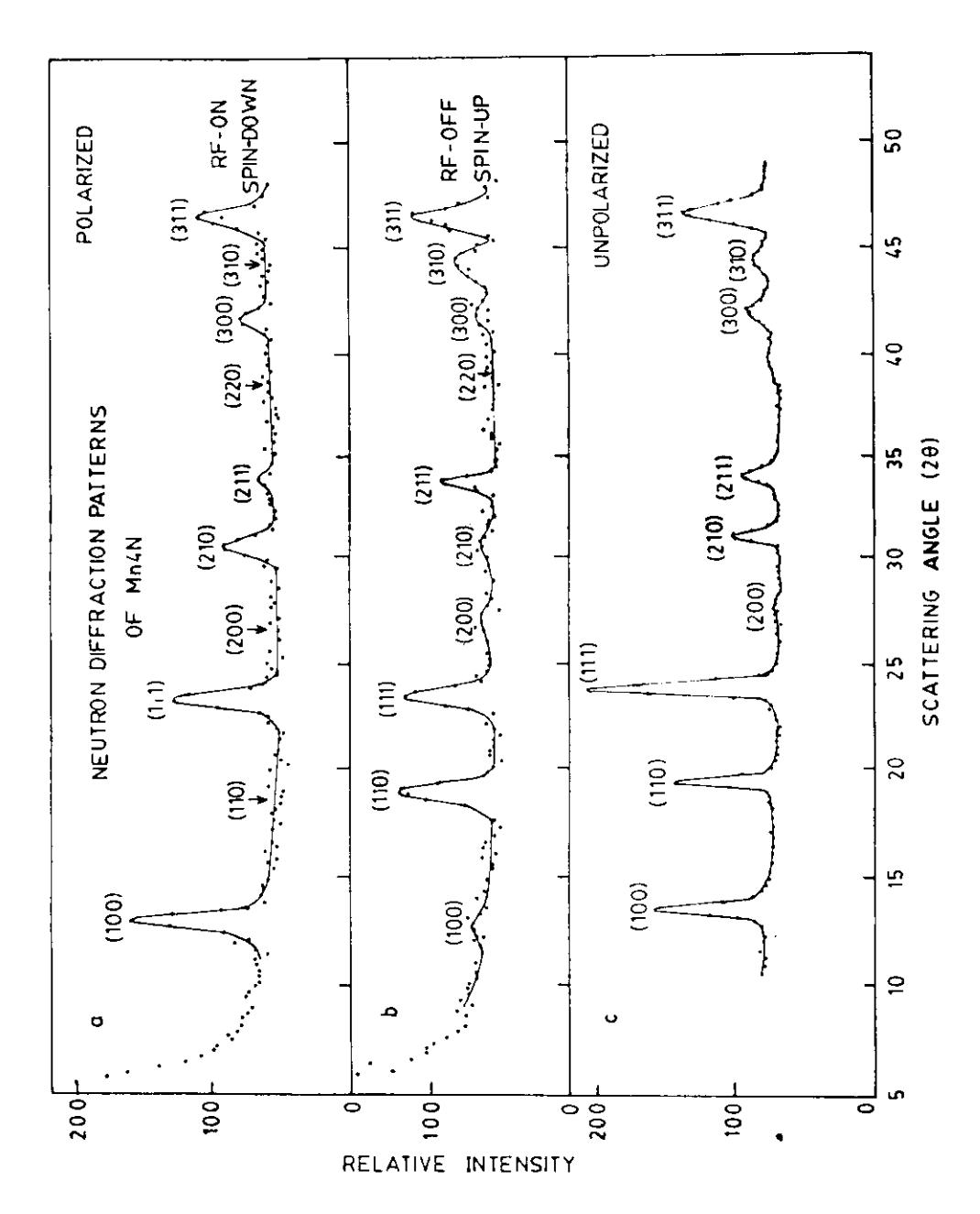
Fig. 4 Powder diffraction patterns of \(Mn_4N\) at room temperature for neutrons polarized parallel (a) and anti-parallel (b) to the magnetizing field. Unpolarized neutron pattern (after converting the wavelength to 0.92 Å) is also shown (c) for comparison.