

SARJ
Suatu penyelidikan dilakukan terhadap pasangan roda gigi miring yang rncmiliki spesifikasi sebagai betikut : /ord I contact rotio lebih be sar dari 2,0 d an overlap rotie lebih kecil dari I ,0. Dalam penyeiidikrn ini dibuat suatu rc1 r?p percobaan untuk mengukur pcngaruh kewlaharr pemasangar poros roda gigi terhadap karakteristik getaran maupun r€gangan yang terjadi pada roga gigi miring tersebut. Besaran yang diukur mencakup percepatan (akselerasi) getaran, regangan pada akar gigt, dan dilakukan pula analisa frekuensi terhadap sinyal getaran tersebut.
Data yang diperoleh menu jukkan bahwa tingkat kesalahan pemasangan yang tertentu memberikan pengaruh yang besar te(hadap karakteristik getaran maupun pola regangan pada roda gigi miring tersebut. Kesalahan deviasi poros maupun inklinasi poros yang sama besar, yang terjadi pada sisi depan dan pada sisi belakangan roda gigi, ternyata menghasilkan karakteristik getaran maupun harga regangan yang berbeda.
Guesr resenrcher,l\'lechanical l_ngjreerin! Deportmcnt. Ba.ndung lnslilule ofTcchnolDgy. Jl. Ganesha l0 Bandung. lndonesia.
Professor, Research Lab. ot Precision Machinery and Elecrrcnics, Tokyo lnsdtute of Technology Nagalsuta, Midori-ku Yokohama 227, Japan.
Graduate Sludenl, Craduatc School ofCoordinated Sciencc, fokyo lnstitute otTechnology
l. Review of research on gear vibration by Prof. Umezawa, er 4r.
Helical gears area widely used for power transmission in vehicles and for application where smooth tooth meshing condition is required. It is known that stiffness of the gear pair has a strong influence on vibration as well as on dynamic load which occured during power transmission.
At the Laboratory of Precision Machinery and Electronics of Tokyo lnstitute of Technology, Japan, intensive ongoning research works on gear vibrations, including gear noise prcblems have been conducted by Prof. Umezawa and his group. Emphasis of the research were initially devoted in formulating the governing equations of gear tooth deflections and their solution. It was soon followed by research effods to determine tooth meshing conditions and tooth deflection along the contact lines on helical gears. As a result, formulas for approxirnating del'lection of gear tooth and bending montent distribution of gear tooth were developed. The validity of the approximations wefe subsequently determined by comparing the calculated values with measured values obtained from a rnodeled gear tooth (3,4,5). Measurements on actual gears were the next research undertaking to analyse the tooth meshing and the behavior of the driven gear under static lood and under lood transmission. Tooth profile modifications were implemented in a number of tests to reduce the level of gear vibrations. Experimentations using a novel tooth flank modification method, as proposed by Prof. Umezawa, were conducted and the measured results were in good agreement with the calculated values from the theoretical approximations ( 6,?,8).
In real life situation, a gear assembly is seldom free from errors. These errors nray be present due to manufacturing erors of the tooth and/or assembling errors of the gear. Several research actiyities were therefore carried out to investigate the influence of gear errors on gear vibration. Of particular interest was the rotational vibration on spur geius caused by pressure angles as well as nornul pitch errors. In order to investigate this complex problem, a computer progranr was developed to sinulate the gear vibration on spur gears. The results obtained by this simulation were validated by measured values from experiments. To examine the influence of Transverse Contact Ratio (TRCR) and overlap Ratio (OLR) on the level of vibration, Prof. Umezawa proposed to categorizc the helical gears into three different classes ( I I ) :
I . Class I : (TRCR + OLR) less than 2.0 2. Class II : (TRCR + OLR) greater or equal to 2.0, but (OLR) less
tlian I .0
3. Class III : (OLR) greater than 1.0.
Presently the rL'search activities on gear include the investigations of gear noise
problems, gear vibration induced by gear shaft misalignments, influence of shaft length on gear vibration, and research on different types of gears.
2. The present work
Stiffness on tooth meshing has been reported to have a significant influence on the nature of vibration on helical gears. Furthermore, improper alignments between the shafts on a pair helical gear during power transmission affect the tooth meshing stiffness and the load distribution along the tooth facewidth. To determine the influence of gear shaft misalignments on vibration during power transmission, a series of experiments have been conducted for three different classes of helical gears.
Simultaneous measurements were conducted on the vibration and the tooth root strains during tooth meshing. Tooth root strains, in particular, were measured by using strain gages implanted at several tooth root fillets. In addition, by incorporating a pair of spur gear in the experimentation, it was possible to perform a comparative study among the different classes of gears.
Helical gears used in the experiments were selected from the threc different classes, and designated as: Hl (from class I), H2 (from class II) and H3 (from class III). The spur gear was assigned as S.
In this partial report, only the experirnental results from helical gear H2 will be discussed.
3. Line of action of helical gear (LAHG)
On helical gears, the gear tooth lns a certain helix angle and consequently the line of contact on a pair of helical gear teeth during tooth meshing is not parallel to the tooth tip edge. The condition during tooth meshing between a pair of helical gear teeth, showing the geometrical arrangement as well as thc terminologies used in this report, is illustrated in Figure l-
Tooth meshing starts at point a' and during this action, the line of contact moves along bb',c',cc", d'd " on the plane of action. Tooth meshing is completed when the line of contact reaches point f:
To analyse the line action of helical gcar (LAHG) during tooth meshing, it is necessary to specily that:
- (a) LAHG is located in the middle of the tooth facewidth, and on the plane of action.
- (b) The origin of LAHG coincides with the pitch point of the helical gear.
Consequcntly, rhe LAHG of il point a. and the meshing point at point f. pair of helical gear teeth starts meshing at moves through point b, c, d, e and terminates
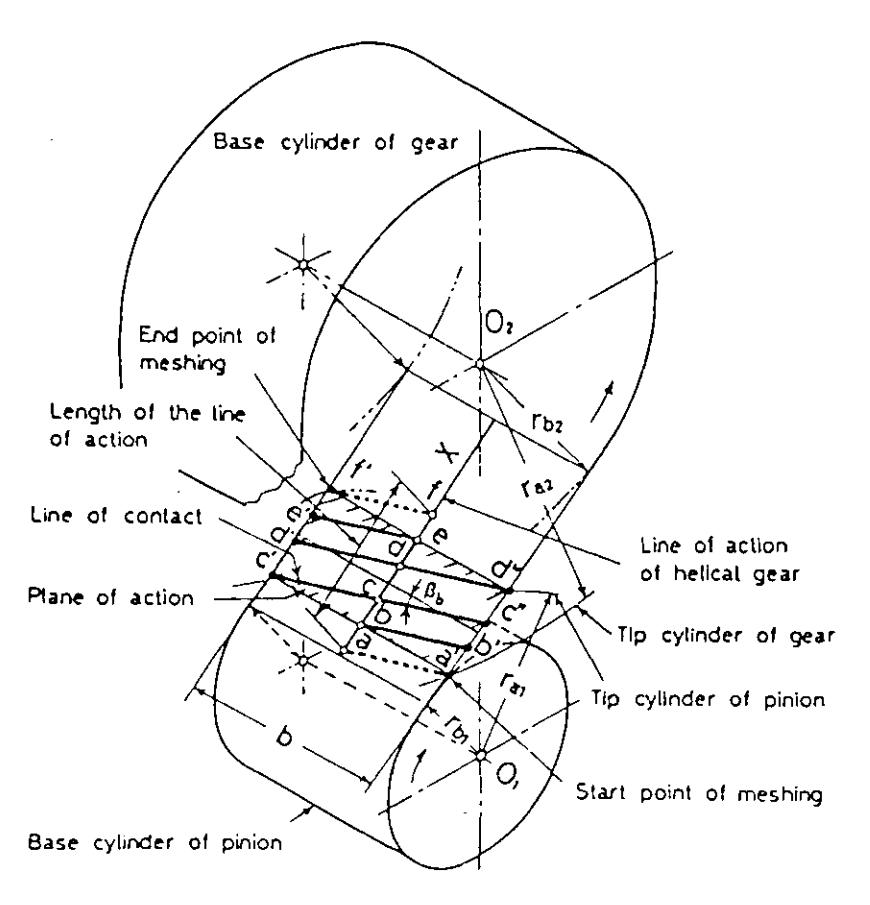
Figure 1 The line of action of helical gear (LAHG in briefl
4. Experiment
4.I Instrumentation arul Experimental Set up
Tire arrangenrent of the mechanical components of tlte experimental set up is illustratcd in FGure 2. The input shatl of the tested gear pairs (l) was connc'cted bya V-bclt to a variable specd 55 KW induction motor(6): and the output shlft was coupled to an eddy current type dynamometer. Two piezoelectric type accelerometers (ntanufacturer code: BBN 50[ ) were attached at 180 degree, opposite to each other, on each side of tlre gear blank. Each accelerometers had the following specifications : 5 mm in diameter, l0 mm long and weighted 2 grams. The sensitive direction of both accelerometer positions were arranged such that any one of the three different kinds of vibration, i.e, rotational (torsional), radial (transversal), and axial vibration coukl be measured.
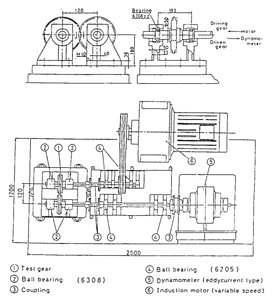
Figure 2Set up of the mechanical components
The arrangement of electrical instrumentations is schematically shown in Figure 3. The rotational spebd of the induction elcctric motor flM) was controlled either manually by using a speed controller (SC), or automatically by combined use of speed controller and a swecp oscillator (SWO). The transmitted torques were delivered by eddy current type dynamometer (ED) adjusted through torque controller (TC).
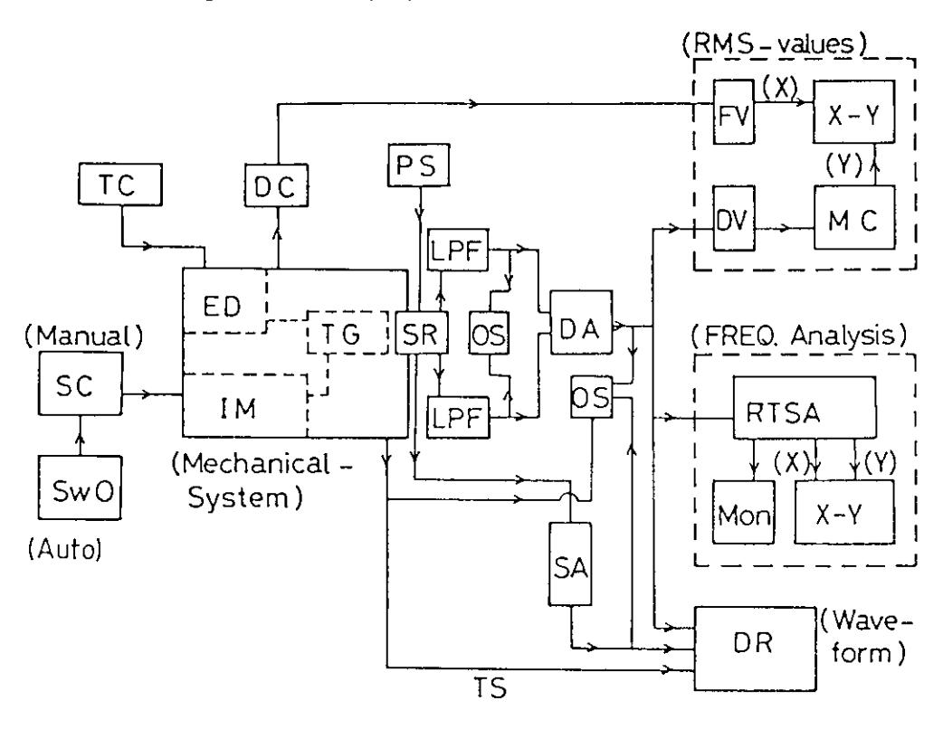
Figure 3 Schematic arrangement of the electronical instrumentations
| DA | : dual differential amplifier | PS | : polver supply |
|---|---|---|---|
| DC | : digital counter | RTSA : real time spectrum analyzer | |
| DR | : tape recorder | SA | I strain amplifier |
| DV | : digital voltmeter | SC | : speed controller |
| FV | : frequency to voltage converter | SR | : slip ring |
| lM | : induction electric motor | SwO | : sweep oscillator |
| LPF | : low pass filter | TC | : torque converter |
| MC | : mini computer | TG | : tested gear |
| OS | : oscilloscope | TS | : triggering signal |
| X-Y | : x-y recorder |
Additional anangement of strain gages for ments at different tooth root fillets as well meters are shown in Figure 4. dynamic load and strain measureas the positions of both accelero-
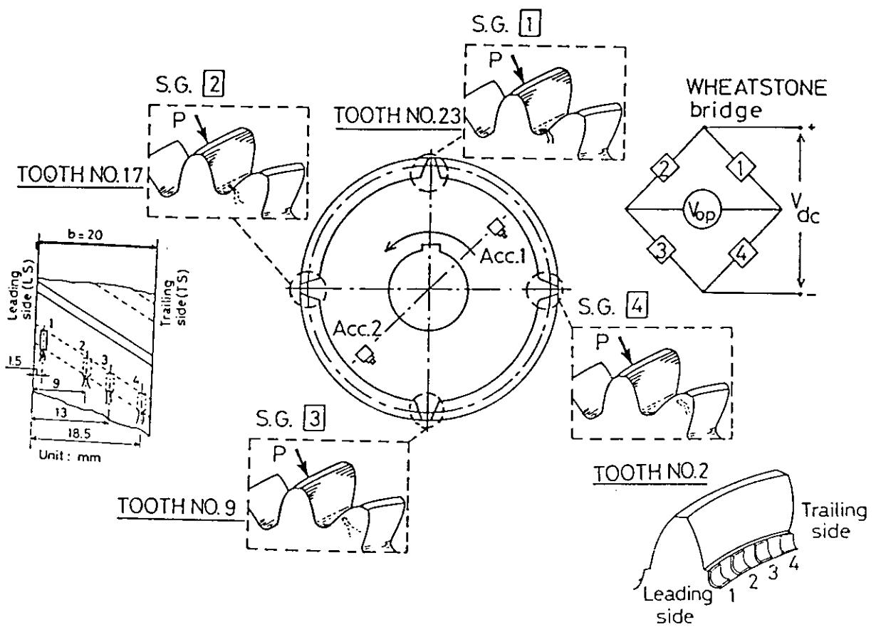
Figure 4 Strain gages and accelerometers arrangement
Data acquisition was conducted as follows. The acceleration signals neasured by the accelerometers were sent to two low pass filters (LPF) and thet outprrt signals were combined in a dual difl'erential amplifiers (DA). Meanwhile strains measured by the strain gages at tooth root wcre amplified by a strain amplifier (SA). These measured signals, i.e, accelerations and strains. were sent front the nrechanical systenr to the peripheral instruments through a slip ring (SR). The output signals fronr the differential antplifiers and the strain amplifiers subsequcntly became thc measured cxperimental data ready to be processed or stored lor later use.
4.2 Data processitrg
Tlrce kinds of data processing were pcrformed, narnely:
(a) RMS valucs of the vibration level
The output of the differential anrplifier (DA) represcnting the vibration levcl (in tenns ot acceleration) was nreasured by a digital voltnleter (DV) and its digital output signals were then averaged by a nlini computer (MC). The averaged values (llMS-valucs) of the acceleration signals hence becante the assigned value of thc Y-ordinate in the X-Y plot. At the &?ntc tinte, the varying rotational speed of the output shalt of thc tested gears (TC;), having a reduction ratio of I .0, was tallied by a digital counter (DC). Using frequcncy to voltage convcrter (FV) the pulses wcrc convcrtcd into analog voltage signal and assigned as the moving valrres of the X-lbscissa in the X-Y plot.
(b) Frc<1uc ncy analysis data
A real tinre spectrunr analyzcr (RSTA) was used to process the output signal of the differential amplificr from the time domain to the frequency domain. The results werc plotted on an X-Y coordinate system with the X-axis rcpresenting thc lieqLrency and th(- Y-uxis as the vibration level.
(c) Wavc lorm data
Data in the timc dornain were recorded by a tape recorder. These data included the acceleration signals from the differential amplifier (DA), the strain signals from thc stra in anrp lifier and one-pulse p(-r rcvolution triggering signal ( TS ). By retrieving the data frorn the tapc, data observations and analyses were accomplished using plots obtained from a pen recorder.
4.3 Aligument of gear shaft
In addition to rotational speed and transmitted torquc tlut were sclected as measuring parunlcters. shaft alignrnents were also introduccd as another parameter. Two kinds ol shaft misalignments, i.c. shaft deviation and shaft inclinatioll. were consiclcrcd in thc experiment. 'l-ile tenninologies used in tiris report to describe the alignment of the gear shaft are in accordance with the ISO standard.
In the actual experimental set up, the shaft misalignments were obtained by inserting several slip gages either on the surface of the plate or on its side surface, as shown in Figure 5. The thickness of the slip gages chosen for the experiment were 0.2 mm and 0.4 mm. The resulted shaft deviation and shaft inclination were measured by two dial indicators. For tooth facewidth of 20.0 mm, the angular error and the alignment error resulted from two different slip gage thicknesses are shown in Table 2.
Table 1 Tested gear specification and its classification
| Gear number | H1 | H 2 | Н3 | S |
|---|---|---|---|---|
| Face width (mm) | 10 | 20 | 25 | 10 |
| Module | 3.5 | 4 | ||
| Pressure angle (*) | 20 | • | 20 | |
| Helix angle (*) | l | 30 | 0 | |
| Number of teeth | 30 | 30 | ||
| Reference diameter(mm) | 121.7 | 1200 | ||
| Addendum modification coefficient | -0.172 | 0 | ||
| Transverse contact ratio | 140 | 1.65 | ||
| Overlap ratio | 045 | 0.91 | 1.14 | |
| Contact ratio | 1.85 | 2.31 | 2.54 | 1.65 |
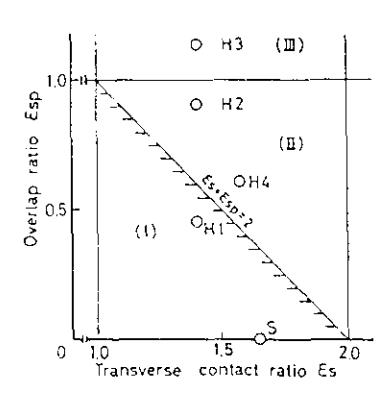
Table 2 The values of shaft deviation and shaft inclination
| Slip-g. | Shaft Deviation | Shaft Inclination | |||
|---|---|---|---|---|---|
| thickness ( mm ) | \(\theta\) (rad) | For b = 20 mm | \(\theta\) (rad) | For b = 20 mm | |
| 0,2 | 5.6 × 10⁻⁴ | 11.1 μm | 5.9 × 10⁻⁴ | 11.9 μm | |
| 0.4 | 1.12 × 10⁻³ | 22.3 μm | \(1.14 \times 10^{-3}\) | 22.8 μm | |
a. ISO standard for shaft alignment
b. Realization of improper shaft alignment
Figure 5 Shaft deviation and shaft inclination
5. Experimental resrlts of vibration measlrements on helical gears H-2
5.1 Influence of rotatianal peed on vibration level for different gear shaft alignments
In these experiments, three kinds of vibration level (in terms of RMS values) were measured, i.e:
- (a) Rotational (torsional) vibration
- (b) Radial (tranwersal) vibration
- (c) Axial vibration
For the three different kinds of vibration level, measurements were carried out by varying the rotational speed in a continuous manner from about 600 RPM to 3400 RPM. At the same time, the RMS values of the accelemtion level were measured for the torque transmission of I 47 N.m ( l5kgf .ln).
The obtained results were categorized into two major findings, namely:
- (a) The influence of gear shaft deviation on rotational, radial and axial vibrations, respectively.
- (b) The influence of gear shaft inclination on rotational, radial and axial vibrations, respectively.
The results area presented in Figure 6 for gear shaft deviation, and in Figure 7 for sear shaft inclination.
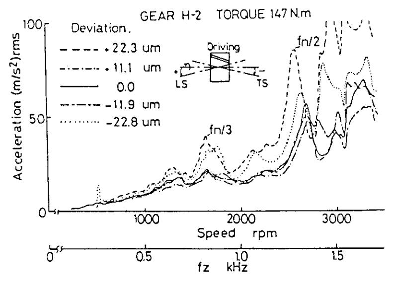
a. Rolational (torsional) ..'ibrat lon
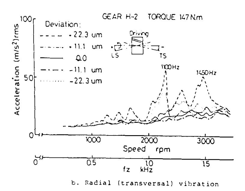
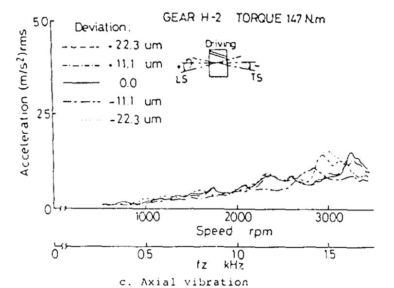
Figure 6 Influence of rotational speed on vibration level for gear shaft deviation
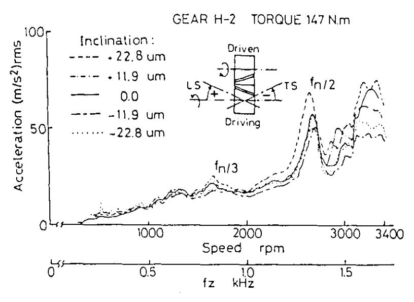
a, Rotational (torsional) vibration
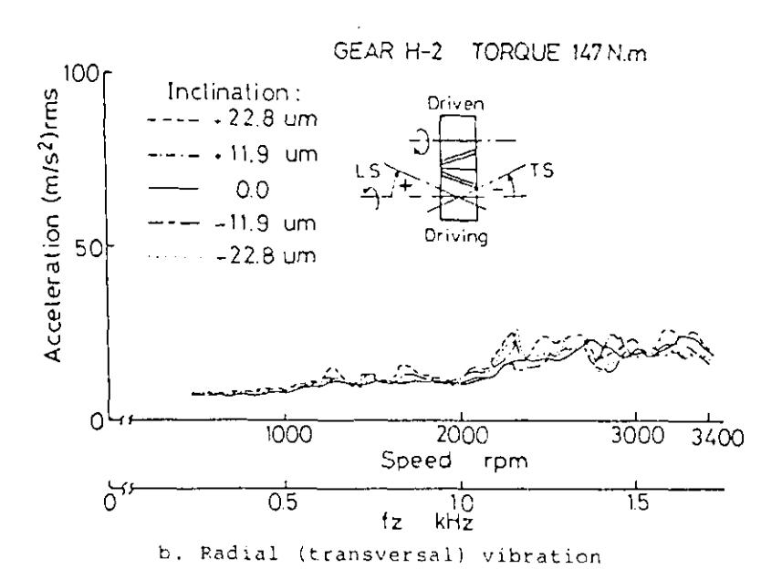
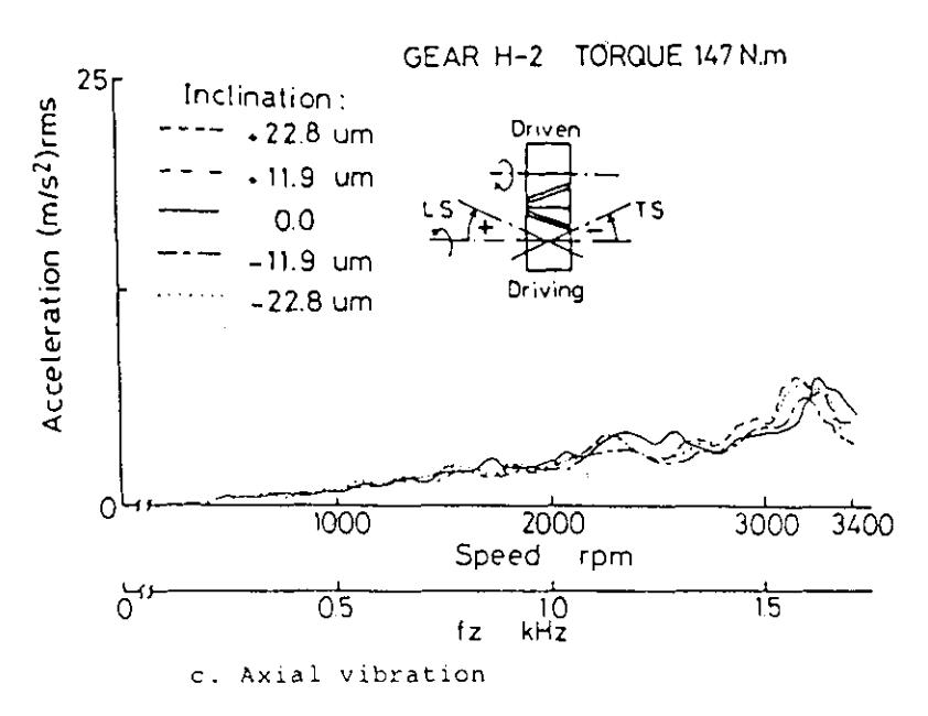
Figure 7 Influence of rotational speed on vibration for gear shaft inclination
Discussions
- (1) In general, the gear shaft deviation gave significant influence on vibration level. On the other hand, the shaft inclination error exerted influence only to a minor extent on the vibration level. Furthermore, errors at the gear leading side yielded higher level of vibration as compared to the errors at the gear trailing side.
- (2) For both shaft misalignments, i.e. shaft deviation and shaft inclination, the highest level of vibration occured on rotational vibration, followed by radial vibration, and the lowest on axial vibration. Henceforth, the axial vibration, on the tested helical gears H-2 was neglected in the subsequent investigation.
- (3) With respect to the vibration level of proper gear shaft alignment, error values of 11.1 \(\mu\)m and 11.9 \(\mu\)m (corresponding to slip gage thickness of 0.2 mm) did not render much influence. However, error values of 22.3 \(\mu\)m and 22.8 \(\mu\)m (corresponding to the slip gage thickness of 0.4 mm) produced significant influence on the level of vibration at the gear leading side and at the gear trailing side as well.
- (4) Curve peaks, which for some cases corresponding to fn/2 and fn/3, shifted toward lower rotational speed (lower tooth meshing frequency) for both
type of misalignments. These shifts were clearly observed for curves with error values resulted from slip gage thickness of 0.4 mm.
(5) For error values corresponding to the gage thickness of 0.4 mm, the radial vibration level caused by gear shaft deviation was, generally, higher than the one produced by gear shaft inclination.
5.2 Influence of transmitted torque on rotational vibration for different shaft alignments
As was discussed earlier slip gage thickness of 0.4 mm produced values at the gear leading side as well as at the gear trailing side which caused rotational vibration to occur at high vibration level. Therefore, the following investigation was conducted on rotational vibration primarily to explore the behavior of torque transmision and the level of vibration due to improper gear shaft alignment.
On a graph of acceleration level (RMS values) versus rotational speed, the values of acceleration level at different rotational speeds, i.e.: 800, 1000, 1460, 2000, 2150, and 2300 RPM were plotted for a variation values of torque transmission values of 49.0, 73.5, 98.0, 122.5, and 147.0 N-m. These rotational speeds were selected because they produced vibrations beyond the resonance frequencies but still in the normal range of operating speed.
For data processing, the maximum transmitted torque was specified to be 147.0 N-m, corresponding to the tangential transmitted force of 2800 N (285.7 kgf) on the pitch circle.
The computed results of gear shaft deviation and gear shaft inclination are presented in Figure 8 and 9, respectively. These plots are in good agreement with the compiled result of Figure 10, presented as the composite curves of different torque transmission values.
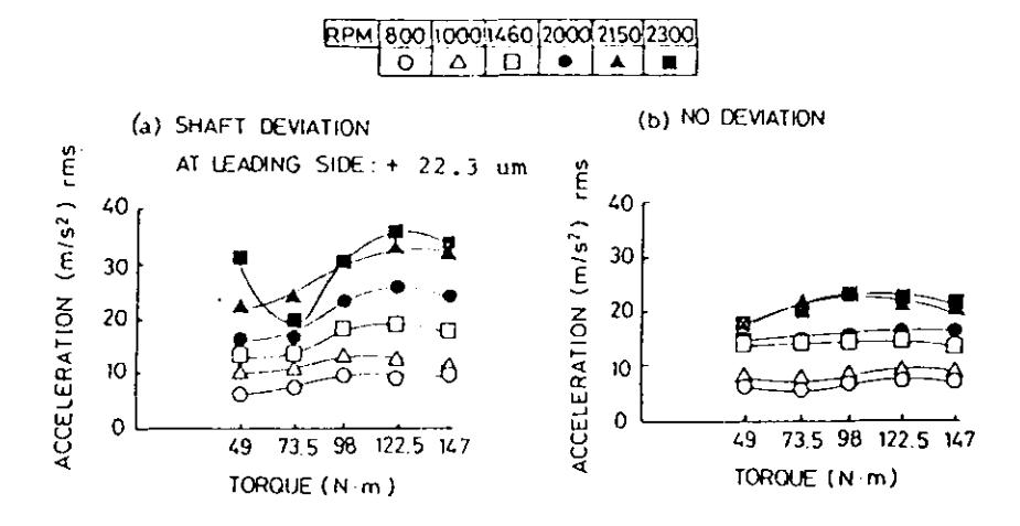
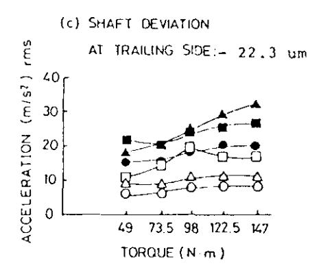
Figure 8 Influence of transmitted torque on rotational vibration for gear shaft deviation
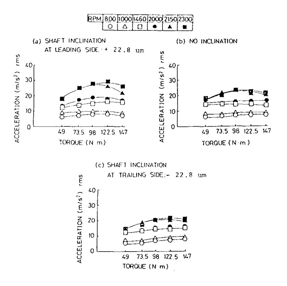
Figure 9 Influence of transmitted torque on rotational vibrational for gear shaft deviation
Discussions
Based on the results shown in the previous figures, the following cases can be discussed, namely:
- (1) In general, the curves suggest an increasing level of rotational vibration, at a constant rotational speed, when the transmitted torque is increased.
- (2) With higher rotational speeds i.e.: 1460, 2000, 2150, and 2300 RPM, the increase of torque transmission yielded higher level of vibration on gear shaft deviation (corresponding to the slip gage thickness of 0.4 mm) than on gear shaft inclination.
- (3) Likewise, for both gear shaft misalignments, i.e.: gear shaft deviation and gear shaft inclination, errors at gear leading side produced higher level of vibration than the one caused by errors at the gear trailing side.
- (4) The composite graphs presented in Figure 10, shown that the curve peaks, which correspond to half and onethird of the tooth meshing resonance frequency, shift toward higher rotational speed (tooth meshing frequency). These tooth meshing resonance frequencies were determined by frequency analysis of the vibration signals. In addition, gear shaft deviation of 22.3 μm due to improper shaft alignment caused the level of vibration to increase if the transmitted torque values were increased. These conditions were clearly observed for rotational speed of 800 RPM to 3400 RPM.
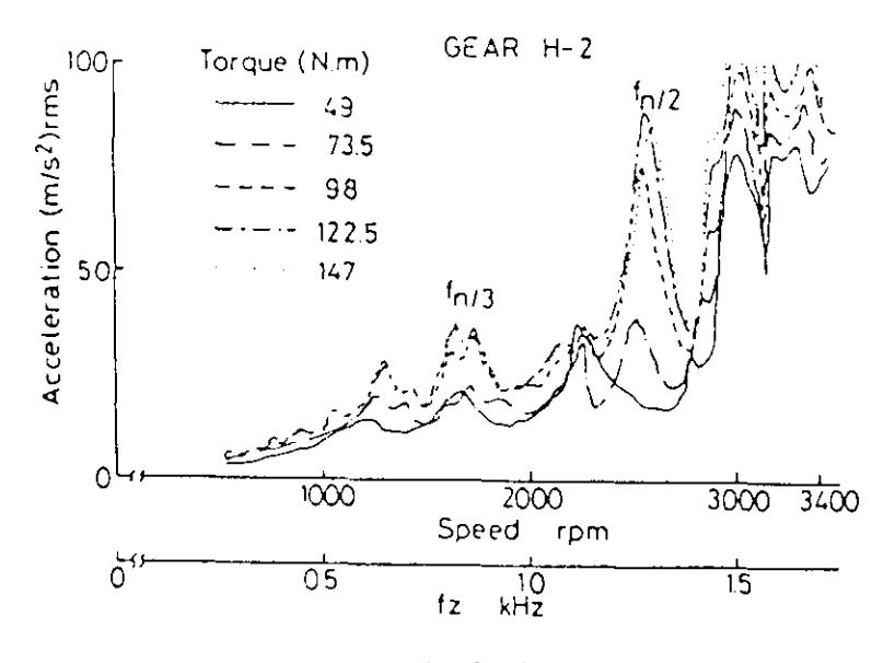
a. Gear shaft deviation at the gear leading side: + 22.3 um
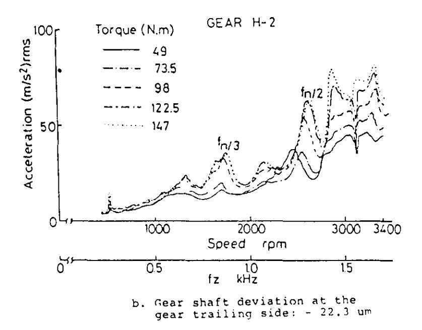
Figure 10 Influence of rotational speed on rotational vibration for different values of transmitted torque
6. Experimental results of strain measurement on helical gears H-2
6.1 Tooth root strain along the line of action for different strain gage positions
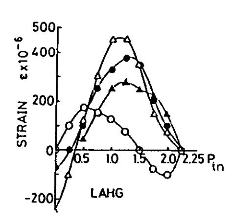
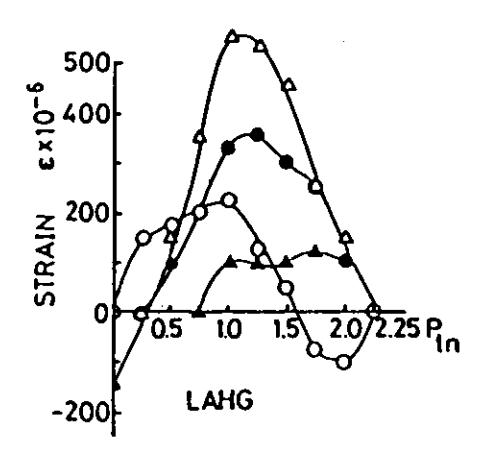
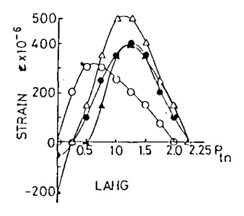
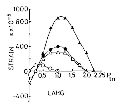
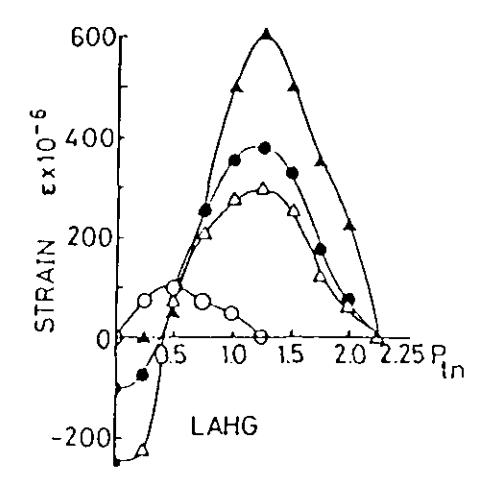
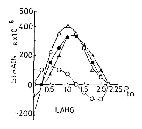
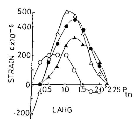
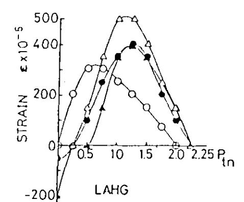
In order to know the behavior of tooth root strain along the line of action (LAHG) during tooth meshing of a pair of helical gear teeth, the strain values on ten different positions along LAHG, i.e.: 0, 0.25, 0.5, 0.75, 1.0, 1.25, 1.5, 1.75, 2.0, and 2.25 Ptn (where Ptn is the transverse normal pitch) were evaluated and plotted. The evaluations were carried out on the strain wave form data, at a constant transmitted torque of 196 N-m (20.0 kgf.m). This torque value corresponded to the tangential transmitted force of 3733.3 N (380.95 kgf) on the pitch circle. The plotted result are shown in Figures 11 and 12 for gear shaft deviation and gear shaft inclination, respectively.
Similar data have been evaluated for transmitted torque of 98 N.m (10.0 kgf.m), and the obtained results show similar strain conditions except the strain amplitudes were smaller than those ones obtained for the transmitted torque of 196.0 N.m.
Discrusions
- ( I ) Gear slnft deviation and gear shaft inclination
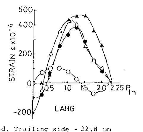
- a. Figures I I and 12 showed that the maximum tooth root strains caused by shaft deviation is higher than those ones caused by shaft inclination. When the gear shaft deviation at the gear trailing side is 22.3 tm the highest strain value is 880 pe, corresponding to a stress value of l8l .3 MPa or 18.5 kgf/mm2. But when the gear shaft inclination at the gear leading side is 22.8 pn, the maximum strain is 500 trre , corresponding to a stress value of 103.0 MPa or 10.5 kgf/mm2. Both shaft alignment errors were obtained from slip gages thickness of 0.4 mm.
- b. For both gear shaft misalignments, errors at the gear leading side deated an opposite strain phenomenon at the position of strain gage I . However, it did not occur for the same error at the gear trailing side; except for shaft irclination of 22.8 pm.
- c. Errors at the gear leading side increased the strain at the position of strain gage 2, but it suppressed the strain at strain gage 4. On the other hand, errors at the gear trailing side generated an opposite condition.
- d. Errors distorted the tooth root strain distribution of a proper gear shaft alignment; however, the maximum tooth root strain still occured around 1.0-1.25 ftn.
- (2) Errors at the gear trailing side caused a maximum tooth root strain values which were higher than those ones generated by ermrs at the gear leading side, as slrcwn in Figure I l.
a. I€.ding side + ll,l un b. Leading side + 22,f u r
c. No error

GEAR H-2 TORQUE 196 N.m STRAIN GAGE :
0-0-0 | Leading side
Δ--Δ---Δ
●-●--● 3:
▲ ▲ 4 Trailing side
e. Trailing side - li,1 um
Figure 11 Tooth root strains along the line of action at different strain gage positions. Gear shaft deviation
(3) Gear shaft inclination
With respect to the tooth root strain of proper gear shaft alignment, inclination error did not affect the tooth root strain severely, except to strain gage 1. Maximum tooth root strains occured around 1.0 to 1.25 Ptn; and their values were slightly lower than those ones of the proper gear shaft alignment.
a. Leading side + 11,9 Uit
b. Leading side + 22,8 um
c. No error
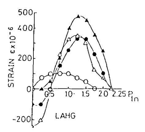
-∆--∆ 2
O-O-O 1 Leading side
GEAR H-2
STRAIN GAGE:
4 Trailing side
e. Trailing side ~ 11.9 um
Figure 12 Tooth root strains along the line of action at different strain gage positions. Gear shaft inclination
TORQUE 196 N.m.
6.2 Tooth root strains during tooth meshing at different strain gage positions
During tooth meshing, tooth root strains at four different strain gage positions were examined for a set of constant values of Ptn. The tooth root strains along the tooth facewidth for Ptn values of 0.25 (at the start of tooth meshing), 1.5, 1.0 (during tooth meshing), 1.5 and 2.0 (at the end of tooth meshing) were observed at different times. These observations described the load distribution as well.
The results are shown in Figures 13 and 14 for gear shaft deviation and gear shaft inclination, respectively. The evaluation was carried out for the transmitted torque of 196 N-m (20.0 kgf-m).
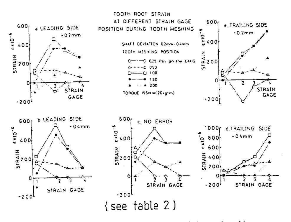
Figure 13 Tooth root strains different strain gage positions during tooth meshing. Gear shaft deviation.
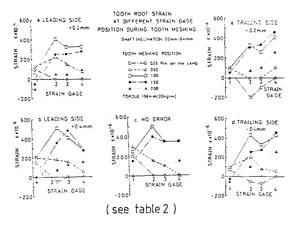
Figure 14 Tooth root strain at different strain gage position during tooth meshing. Gear shaft inclination
Discussions
- (1) The gear shaft deviation of 11.1 \(\mu\)m and 22.3 \(\mu\)m at the gear leading side yielded tooth root strains similar to those which occured with proper gear shaft alignment. The maximum strain of 55 \(\mu\epsilon\) (the stress of 113.3 MPa or 11.6 kgf/mm²) was observed at strain gage 2 for Ptn value of 1.0. On the other hand, errors at the gear trailing side yielded maximum tooth root strain of 850 \(\mu\epsilon\) (the stress of 175.1 MPa or 11.6 kgf/mm² at strain gage 4 for Ptn values of 1 and 1.5.
- (2) The relationship of tooth root strains and gear shaft inclination showed similar trend as the tooth train versus gear shaft deviation relationship, except the strain values were smaller. The maximum strain of 125 \(\mu\epsilon\) (the stress of 25.8 MPa or 2.6 kgf/mm<sup>2</sup>) was observed for Ptn value of 1.0 at strain gage 2.
6.3 Maximum tooth root strain at different st/ain gage positions
Evaluation of the recorded strain data (wave form measurements of the strain) was also carried out to show the relationship between the maximum tooth root strains at four different strain gage positions with the two gear shaft alignment effois. Both gear shaft alignment erors were evaluated either at the gear trailing side or at the gear leading sidc. The evaluation was made for the transmitted torque of I 47 N-m ( I 5.0 kgf-m) and the obtained results are shown in Figure 15-
GEAR :H_2 TORQUE:147N.M(15KgTM) STRAIN GAGE POSITION: 1231' 0.07 0.41 0.59 0.84 Ptn
I--f L5+0.4nrm Cl-_oNO ERROR A- . TS-0.4mm t-}-{l LS'02nrm A-'{ TS-0.2mm : GEAR Ltf"0lNC Slllt TS : GEAR TRAILING SIDI
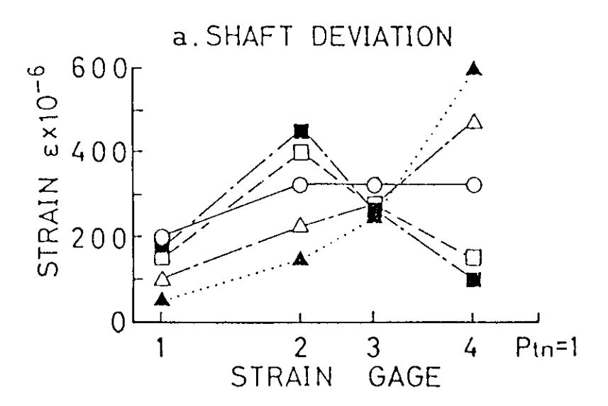
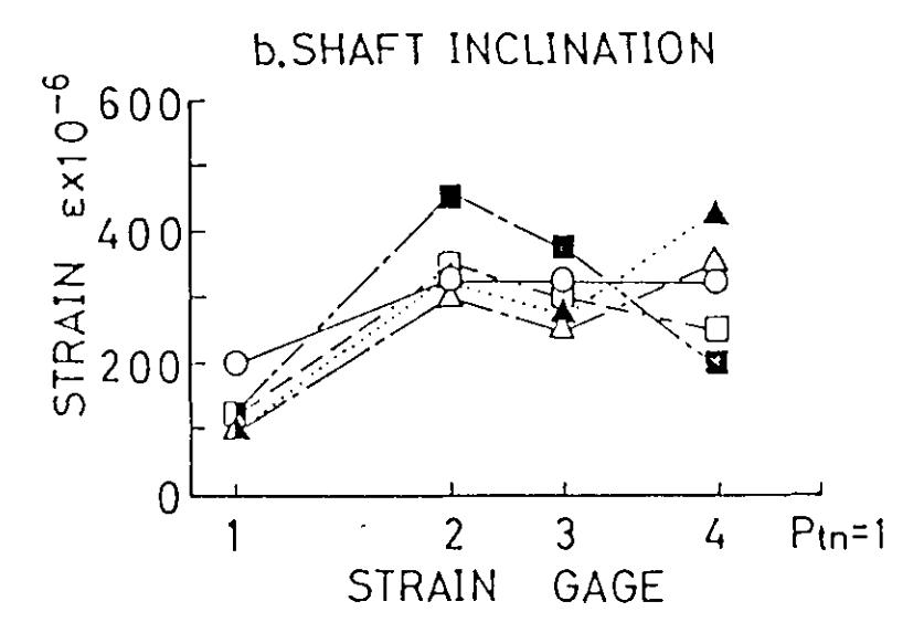
Figure 15 Maximum tooth root strain at different strain gage positions and different gear shaft alignment.
Discussions
- (1) From the strain measurements, it was observed that a pair of helical gears H-2 were sensitive to gear shaft misalignment, particularly to the gear shaft deviation at the gear trailing side. On the other hand, they are less sensitive to gear shaft deviation at the gear leading side. For the transmitted torque of 147 N-m, corresponding to the tangential transmitted force of 2800 N (285.7 kgf) on the pitch circle, the maximum strain value was 575 \(\mu\epsilon\) (the stress of 118.5 MPa or 12.1 kgf/mm<sup>2</sup>).
- (2) For proper gear shaft alignment, it was observed that the strain values were not much affected by gear shaft inclination, except when the gear shaft deviation at the gear leading side reached 22.8 \(\mu\epsilon\).
7 Conclusions
An experimental set up, deviced for gear vibration and gear strain measurement, has been successfull built to measure the RMS values of gear acceleration, to carry out frequency analysis of gear vibration signals on a pair of helical gears. This set up was also capable of reading signals of: (1) gear vibration, (2) tooth root strains, and (3) one-revolution triggering pulses in the time domain. Measurements were conducted on a pair of helical gears with the following specifications, i.e., the total contact ratio of over 2.0 and the overlap ratio of less than 1.0.
It.was observed, among the three modes of misaligned helical gear vibrations, the highest vibration level occured by rotational (torsional) vibration.
Gear shaft alignment errors (gear shaft deviation or gear shaft inclination) at the gcar lcading side has sgnificant influence on the gear vibration characteristics, i.e., RMS values of the acceleration and tooth meshing frequency. This is especially evident for error value of 22 pm obtainable by the slip gage thickness of 0.4 mm.
In addition, if the valuc of transmitted torque was raised, the level of the gear rotational vibration increased accordingly.
Gcar shaft deviation or gear shaft inclination at the gear trailing side strongly influenced the tooth root strains on these helical gears.
Finally, the calculatcd data should be helpful in constructing other theoretical models of vibration of misaligned helical gears.
8 Acknowledgement
One of the authors who was a guest researcher of Prof. Umezawa at the Laboratory of Precision Machinery and Electronics, T.l.T., would like to acknowledge the members of this rcsearch group. Sincere thanks to Mr. H. Houjoh for his kind help, discussions and lriendship. This acknowledgement is also conveyed to tire Japan Society for Promotion of Science (JSPS) for its financial assistancc during the author's sojourn in Japan. Special thanks to the reading comittee of the ITB Proceedings for their corrections and efforts so that the irublication of this paper becomes possible.
9 References
- l. Umezawa, K., J. lshikawa. and K. Hayashi, 'Deflection due to a concentrated load on a cantilever thick plate of finite length for gears', Bull. JSME, Vol. 12. No. 53 (1969). 12.04 l2II
- 2. Umezawa, K., 'Deflections and moments due to a concentrated load on a rack shapcd cantilever plate with finite width for gears',Bull. JSME,Yol. 15, No. 79 ( 1972), 116,130
- 3. Umezawa. K.,'The meslring test on helical gears under load transmission (lst report, The airproximate formula for deflection ofgeartooth)', Bul/. JSME,Yol. 15, No. 90 (1972),1632-1639
- Umezawa, K.,'The meshing test on helical gears under load transmission (2nd report, The approximate formula for bending moment distribution of sear tooth)', -Bull. JSUE, Vol. 16,No.92(1973),407-413
- Umezawa, K. and J.Ishikawa, 'Deflection due to contact between gear teeth with finete width'. rrlll. JSME,Yol. 16, No. 97 ( l9?3), 1085 1093 5.
- Umezawa, K., 'The meshing test on helical gear under load transmission (3rd report, The static behaviours of driven gear)', Bull. JSME, Yol. 17, No. I 12, (1974), 1348 1355 6.
- Umezawa, K. and J. Ishikawa, 'On cylindrical gear without statical behaviours of driven gear under any load', Bull. JSME, VoL 18, No. 122 (197 5\.8'1s -904 7.
- Sato, T., K. Umezawa, and J. Ishikawa, 'Effects of contact ratio and profile corection on gear rotational', Bu . JSME, Vol. 26, No. 221 (1983). 2010-2016 8.
- Umezawa, K., T. Sato, and J. Ishikawa, 'Simulation on rotational vibration of spur gears', B ull. J SM E, Vol. 27, No. 223 (1984r, I 02- I 09 9.
- Umezawa, K., T. Sato, and K. Khono, 'lnfluence of gcar erors on rotational vibration of power transmission spur gear',.Bull. JSME, Vol. 27, No. 225 (1984\ 10.
- Umezawa, K., 'Vibration of power transmission helical gear with narrow facewidth', ASME, 04-Det-l 09 lt.