
1 Introduction
Since the advent of television, display technology has become an inseparable part of various devices. Unfortunately, during outdoor usage these display panels consume a great amount of energy to counter the bright ambient light and moreover outdoor displays are usually large. Therefore, it is desirable to develop a display panel that uses ambient light to produce the image. One option is by using a system that has the property of switchable transparent and reflective states [1].
Various methods have been proposed to control the transmittance/reflectance property. In a system that employs electrochemistry, a controlled voltage is applied to change the chemical characteristic on the surface of electrodes such that the transmittance/reflectance is altered over a specific electromagnetic spectrum [2-4]. Controlling the transmittance/reflectance of the surface mechanically has also been attempted, utilizing a flexible polyethylene terephthalate (PET) sheet [5]. Another study proposed the use of a tandem architecture of the metasurface with transparent/reflective states that can be controlled by dropping liquid with a high refractive index on top of the metasurface [6]. Unfortunately, it is difficult to reach perfect transmission/reflection with these techniques. A more popular way to develop a display panel that uses ambient light is by embedding a transflector in a liquidcrystal-display (LCD) system [7]. However, the working principle of the transflector is somewhat similar to that of a half-mirror, which results in a contrast ratio problem [1,8,9].
Meanwhile, the research on dielectric metasurfaces has reached the state-of-theart level [10]. It has been reported that the dielectric metasurface can show various useful phenomena, including zero forward/backward scattering and nonradiating anapole mode for second and third harmonic generation [11]. One class of metasurfaces is the meta-lattice, a metasurface system based on a periodic arrangement of subwavelength scatterers. Recently, a nanorod-based meta-lattice has been developed to obtain perfect transmission/reflection of an incident plane wave and to steer the direction of the scattered light [12]. Nonetheless, no attempt has been made yet to study the optical property of a metasurface based on nanotubes. In previous reports, it has been shown that the scattering of light by a nanotube can be used for the application of refractive index sensing, directional sensing, and scattering pattern shaping [13-15]. Thus, the present work proposes a new route to utilize ambient light for display applications by means of a nanotube-based dielectric meta-lattice system. The proposed system is capable of reaching near unity reflectance/transmittance – even in oblique incidence light cases – with switchable reflective and transparent states.
2 Theoretical Basis
The proposed system consists of dielectric nanotubes arranged periodically to make a meta-lattice system as shown in Figure 1. Each nanotube has outer radius out, inner radius in, and is separated with a center-to-center distance from the adjacent nanotubes. The hole of each nanotube is filled by a material with a variable refractive index (1.5 ≤ 2 ≤ 1.8). Experimentally, this can be done by
Figure 1 Schematics of the system of interest. Cylindrical nanotubes with inner radius in and outer radius out are arranged periodically with periodicity d in the x-direction to form a meta-lattice system.
employing the birefringence of a liquid crystal [16-19]. The outer layer of the nanotubes considered is made of silicon, with the refractive index value taken from experimental data [20]. Silicon is known to be absorptive for wavelengths below 1.1 \(\mu\)m [21]. Nevertheless, in this study, the silicon nanoshell width is in the order of tens of nanometers, so the effect of absorption is negligible and high reflection of light at optical frequency is possible [22]. The nanotubes are embedded in a background medium with refractive index \(n_0\), which can be chosen arbitrarily. A transverse electric plane wave, i.e. the magnetic field vector polarized parallel to the z-axis, illuminates the meta-lattice system with an incident wavelength taken to be in the visible range. Throughout this work, we assumed zero propagation in the z-direction (\(k_z = 0\)).
Following the multiple scattering theory in cylindrical coordinates, the transmittance and the reflectance of the l-th order diffraction in the system may be calculated from the formulas given below [12,23,24]:
\[R_{l} = \left| \frac{2}{d\sqrt{k_{y,0}k_{y,l}}} \sum_{m=-\infty}^{\infty} \frac{(k_{y,l} - ik_{x,l})^{m}}{k_{0}^{m}} a_{m} \right|^{2},\] (1)
\[T_{l} = \left| \delta_{l,0} + \frac{2}{d\sqrt{k_{y,0}k_{y,l}}} \sum_{m=-\infty}^{\infty} \frac{\left(-k_{y,l} - ik_{x,l}\right)^{m}}{k_{0}^{m}} a_{m} \right|^{2}, \tag{2}\] in which
\[k_0 = \frac{2\pi}{\lambda},\tag{3}\]
\[k_{\mathbf{x},l} = -k_0 \cos \phi_{\mathrm{inc}} + \frac{2l\pi}{d},\tag{4}\]
\[k_{y,l} = \sqrt{k_0^2 - k_{x,l}^2}. (5)\]
The scattering coefficient \(a_m\) can be evaluated from a set of linear equations given in matrix form as [24]:
\[\mathbf{a} = \bar{\mathbf{\chi}} \cdot \mathbf{p},\tag{6}\]
\[\bar{\mathbf{\chi}} = (\bar{\mathbf{I}} - \bar{\mathbf{T}} \cdot \bar{\mathbf{L}})^{-1} \cdot \bar{\mathbf{T}},\tag{7}\] where \(\bar{\mathbf{I}}\) is an identity matrix. The components of the square matrix \(\bar{\mathbf{L}}\), as well as the components of the column vector \(\mathbf{p}\), are given as follows:
\[L_{n,m} = \sum_{L=1}^{\infty} H_{n-m}^{(1)}(Lk_0 d) \left[ \exp(iLk_{x,0} d) + (-1)^{n-m} \exp(-iLk_{x,0} d) \right], \tag{8}\]
\[p_{m,1} = (-i)^m \exp(-im\phi_{\text{inc}}). \tag{9}\]
In Eq. (8), \(H_j^{(1)}(Lk_0d)\) denotes the Hankel function of the first kind. The square matrix \(\overline{\mathbf{T}}\) is a diagonal matrix with components that can be determined easily from the corresponding boundary conditions on the surface of each nanotube.
3 Results and Discussion
First, we consider the reflection of light from the meta-lattice at normal incidence \((\phi_{\rm inc}=90^{\rm o})\). Here, no higher-order diffraction takes place since we set \(\lambda>n_0d\). In Figure 2, the reflectance spectra due to the zero<sup>th</sup> order (l=0) diffraction of the meta-lattice with system parameters \(R_{\rm out}=127\) nm, \(R_{\rm in}=0.625R_{\rm out}, d=2.5R_{\rm out},\) and \(n_0=1.45\) are shown. Initially, the refractive index of the core material is set at \(n_2=1.5\), which returns the dash-dotted green line. In this initial state, the reflectance of the system is below 80% throughout the spectrum, which is visually hard to observe [3,4]. One must also note that in particular the reflectance at \(\lambda=533\) nm (indicated by the vertical dashed line) is zero, which
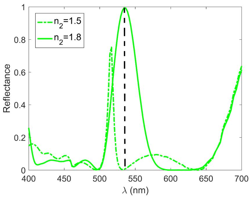
Figure 2 Zero<sup>th</sup> order reflectance spectra of the meta-lattice system for a normal incidence wave with \(R_{\rm out}=127\) nm, \(R_{\rm in}=0.625R_{\rm out}\), \(d=2.5R_{\rm out}\), and \(n_0=1.45\). The dash-dotted and the solid green lines represent the reflectance spectra at core refractive index \(n_2=1.5\) and \(n_2=1.8\), respectively.
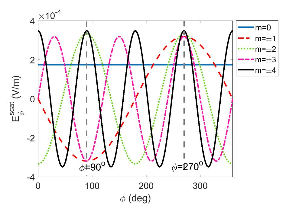
Figure 3 Mode-decomposed angular distribution of the azimuthal component scattered electric field corresponding to the transparent state of Figure 2. The scattering modes at = 90° are out of phase from each other while the scattering modes at = 180° are in phase from each other, resulting in a transparent state.
means a transparent state. Thereafter, upon switching 2 to 1.8, the reflectance spectrum is redshifted, resulting in a reflectance value close to unity at = 533 nm, which may be considered a reflective state. Thus, at this particular wavelength, the transparent and the reflective states can easily be switched by varying 2. The observed redshift can be attributed to the increase of 2, which in turn increases the effective refractive index of the system and subsequently results in the redshift of the resonance wavelength as dictated by the general resonance wavelength rule res = 2eff [11] for systems with a well-behaved dispersion relation. On the other hand, as reported in a previous work, the increase of reflectivity follows from the weakening of transmittance due to the destructive interference between the incident wave and the forward-scattered waves [23].
It is also worthwhile to take a closer look at the physical mechanism underlying the transparent state at = 533 nm in Figure 2. The angular distributions of the azimuthal component of the electric field for each of the first five scattering modes are shown in Figure 3. Here, the system parameters are the same as those in Figure 2 for 2 = 1.5. One immediately sees that at = 270o (i.e. the forward
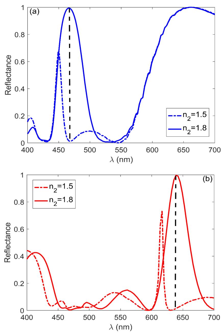
Figure 4 Zeroth order reflectance spectra of the meta-lattice system for a normal incidence wave with (a) out = 107 nm and (b) out = 155 nm. In both figures, the other geometrical and optical parameters are set as in = 0.625out, = 2.5out, and 0 = 1.45. The transformation of the dash-dotted line into a solid line in each figure is caused by the variation of 2 .
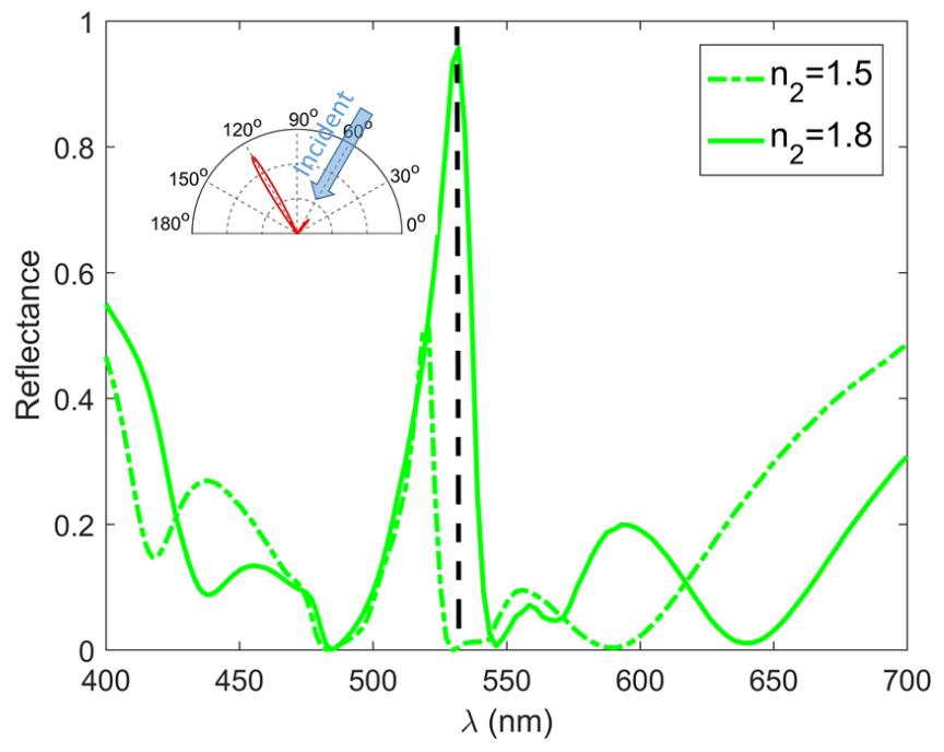
Figure 5 Zeroth order reflectance spectra of the meta-lattice system at incidence angle 30° to the normal direction. The geometrical and optical parameters in the system are set as out = 145 nm, in = 0.6out, = 2.5out, and 0 = 1.3. The dash-dotted and the solid black lines represent the reflectance spectra at core refractive index 2 = 1.5 and 2 = 1.8, respectively.
scattering direction) all scattering modes are in phase, while at = 90° (i.e. the backward scattering direction) the scattering modes are out of phase from each other. This results in the transparent state at = 533 nm observed in Figure 2.
Since the refractive index variation of silicon is well-behaved, the phenomenon exhibited in Figure 2 can be assigned to a different wavelength simply by changing out while keeping the other system parameters at in = 0.625out, = 2.5out, and 0 = 1.45. In Figure 4(a), the outer radius of the nanotubes is set as out = 107 nm to yield the switching mechanism at = 467 nm (see the vertical dashed line), while in Figure 4(b) the switching mechanism is at = 635 nm (see the vertical dashed line) by setting out = 155 nm. Therefore, the system in Figures 2, 4(a) and 4(b) may be combined to serve as a transflective RGB pixel.
For a pixel located near the edge of a display, the incident light direction may be at an angle with respect to the normal direction. To cover this issue, we can use a different system parameter. In Figure 5 we show the zeroth order ( = 0)
reflectance spectra of the meta-lattices with system parameters out = 145 nm, in = 0.6out, = 2.5out, and 0 = 1.3. The incident light direction is tilted 30° from the normal direction. In the initial state, the refractive index of the core is set at 2 = 1.5, which returns zero reflection at = 533 nm. Thereafter, once 2 is changed to 1.8 the reflectance spectrum is shifted to a longer wavelength and results in a reflective state at = 533 nm. Thus, the switching mechanism has again been recovered. Here, reflection because of higher-order diffraction does take place due to the oblique angle of incidence. This is indicated by the presence of the side lobe observed in the polar plot inset of Figure 5, which represents the angular intensity distribution of the scattered wave in the 0 ≤ ≤ region. Nevertheless, the side lobe is negligible compared to the main lobe, so the reflection is dominated by zeroth order diffraction.
4 Conclusion
This study showed the possibility of developing a transflector using a cylindrical meta-lattice system. By employing appropriate geometrical and optical parameters in the meta-lattice it is possible to fine-tune switching between transparent and reflective states at a desired wavelength. The proposed metalattice is able to have reflectance very close to zero in the transparent state and can reach reflectance very close to unity in the reflective state. The transparent state occurs due to the destructive interference between scattered fields of different modes in the backward direction, whereas the reflective state is related to the destructive interference between the incident and the forward-scattered fields. The same switching mechanism can also be found in oblique incidence cases by adjusting the geometrical and optical parameters of the system. Therefore, the meta-lattice system may serve as a promising new route for developing transflective displays. As an outlook for further research, the undesired broadening observed in the reflectance spectra may be circumvented by introducing asymmetry into the system [25-26].
Acknowledgment
This work was supported by Program Penelitian Disertasi Doktor from the Indonesian Ministry of Research, Technology, and Higher Education under Contract No. 2/E1/KP.PTNBH/2021.