
1 Introduction
A circularly-polarized Synthetic Aperture Radar (CP-SAR) to be launched onboard a micro satellite is currently developed in the Microwave Remote Sensing Laboratory (MRSL) of the Center for Environmental Remote Sensing, Chiba University. SAR is a multipurpose sensor that can be operated in all-weather and day-night time. As part of the project, an airborne CP-SAR development is also undertaken in order to gain sufficient knowledge of CP-SAR sensor systems. An L-band CP-SAR system will be designed for operation onboard an unmanned aerial vehicle (UAV).
Historically, synthetic aperture radars (SAR) have used linearly polarized (LP) antenna systems. However, there are limitations due to the propagation phenomenon namely the variation of geometric differences between earth and the radar, the occurrence of a phase shift as a result of radio wave strike the smooth reflective surface, etc. These phenomenon leads to a backscatter variation, random redistribution of returned signal -energy and in the end the formed image would encounter a spatially variant blurring and defocusing as well as ambiguous identification of different low-backscatter features in a scene.
As compared with the conventional linear polarization SAR, most of the above-mentioned effects can be alleviated through the use of CP-SAR. Thus, a CP-SAR sensor would provide a greater amount of information about scenes and targets being imaged than a linear SAR sensor. The present work focuses on the design of an L-band CP-SAR antenna. We consider the SAR system requirements to achieve an excellent performance of the overall CP -SAR system, including optimization of the single element patch and array designing.
2 Circularly Polarized SAR Antenna Requirements
Table 1 Specification of CP-SAR onboard unmanned aerial vehicle
| Parameter | Specification |
|---|---|
| Frequency f | 1.27 GHz (L band) |
| Chirp bandwidth | 10 MHz |
| Polarization | Transmitter : RHCP |
| Receiver : RHCP + LHCP | |
| Gain G | > 20 dBic |
| Axial Ratio AR | < 3 dB (main beam) |
| Antenna size | 1.75 m (azimuth) |
| 0.5 m (range) | |
| Beam width | 8º (azimuth) |
| 25º (range) | |
| Altitude range | 3,000 - 10,000 m |
The capability of a SAR antenna can be described by its sensitivity, spatial resolution in range and azimuth directions, image quality, ambiguities, and swath coverage [1]. Table 1 shows the specifications and targets desired for the present CP-SAR system, which in turn influence the specification of the L-Band CP-SAR antenna.
The operation frequency of 1.27 GHz (L-band) has been chosen, since its relatively longer wavelength ensures better penetration through vegetation canopies. The drawback associated with this choice, however, is the relatively large dimension of microstrip elements. The requirements for the range resolution (15 m) determine the antenna bandwidth of 10 MHz, or less than 1% of the operation frequency of 1.27 GHz. This bandwidth requirement must be compatible with a low axial ratio (AR) (below 3 dB) for ensuring transmitting/receiving circularly-polarized waves. To satisfy the matching of input impedance, the return loss must be smaller than 10 dB in this bandwidth range.
3 CP-SAR Antenna Concept Analysis
The primary considerations in the design and fabrication process are low cost, light weight and ease of manufacturing. The CP-SAR antenna is conceived in the way that every single element microstrip patch is a circularly polarized antenna. Feed network will be implemented in different layer substrate as the feeding method is proximity coupled.
Figure 1 Configuration of a CP-SAR antenna array consisting of microstrip elements
The primary considerations in the design and subsequent fabrication processes are low cost, light weight and ease of manufacturing. The CP-SAR antenna consists of an array of single antenna elements, each being a microstrip antenna for circular polarization. The single element patches which have been optimized are then spatially arranged to form a planar array (see Figure 1 for illustration). The planar array configuration is widely employed in radar systems where a narrow pencil beam is needed [2]. The beam pattern for optimum ground mapping function is cosecant-squared beam in the elevation plane (E-plane) which can correct the range gain variation and pencil beam in the azimuth plane (H-plane) [3]. The antenna side lobe levels in the azimuth plane must be suppressed in order to avoid the azimuth ambiguity. To deal with reflection, the antenna side lobes and back lobes also must be suppressed. A better control of the beam shape and po sition in space can be achieved by correctly arranging the elements along a rectangular grid to form a planar array. The antenna gain is mostly determined by the aperture size and inter-element separation.
To maximize the array performance, certain characteristics of feed networks have to be taken into account. These are the conductor and dielectric losses, surface wave loss, and spurious radiation due to discontinuities such as bends, junctions, and transitions [2]. The loss due to the coupling of the adjacent element have to be considered, therefore isolation between adjacent elements must be higher than 20 dB. The spacing between elements is measured as the distance between the midpoints of each element. A maximum directivity will occur for approximately spacing between elements in the range of 0.8 – 0.9 times the free space wavelength [4].
4 Analysis and Design of Radiating Elements
The configuration of the radiating element together with the microstrip line feed and ground plane is shown in Figure 2 (a), where important parameters are labelled. Side view is depicted in Figure 2 (b). The equilateral triangular radiator will generate a left-handed circular polarization (LHCP) by employing the dual feed method as shown in Figure 2 (a). In order to generate a 90o phase delay on one of the two modes, the line feed on the left side is approximately /4 longer than the other.
Simulations with a finite ground plane model have been undertaken to optimize the size parameters using a full wave analysis tool (IE3D Zeland software) based on the method of moment (MoM) algorithm. The dimensions of the radiator, microstrip feed line and the ground plane for the equilateral triangular patch are a = 102.75, w = 6.8, ld = 21.5, le = 27, ld1 = 6.9, lc = 9.2, ls = 10.1, lm = 3.9, lst = 21.5, ws = 10.2, la = 146.1, and lr =163.1 in units of mm. The geometry model is implemented on two substrates, each with thickness t = 1.6 mm, with the conductor thickness tc 0.035 mm, relative permittivity r = 2.17 and loss tan
(dissipation factor) 0.0005. The equilateral triangular microstrip antenna model has been fabricated to verify the simulation results. The reflection coefficient and input impedance were measured with a RF Vector Network Analyzer (Agilent, E5062A, ENA-L). The antenna gain, AR, and radiation patterns were measured inside the anechoic chamber of MRSL, having a dimension of 48.52.4 m.
The experimental results are shown in Figures 3, 4, and 5 in comparison with the simulation. Figure 3 shows the S-parameter which indicate an impedance bandwidth of more than 15 MHz.
In Figure 4, it can be seen that whereas the gain of the antenna is simulated to be 7.04 dBic at 1.27 GHz, the experimental result shows a smaller value by about 0.6 dB. This difference may be ascribed to the fabrication imperfections (such as inaccuracy in the milling and etching processes and connector soldering) and the substrate loss. The 3-dB AR bandwidth of the simulation is 7.2 MHz and from observation it is 7.4 MHz which is still narrower than the target specification (10 MHz). To improve this situation, the next work will consider the technique to extend the 3-dB AR bandwidth.
Figure 5 shows the radiation pattern in terms of gain an azimuth angle Az = 0o (x-z plane) at the frequency of f = 1.27 GHz. A difference of around 0.7 dB is seen between simulated model and the measured antenna on the gain radiation pattern. There are some differences between the simulated and measured pattern of the antenna. This may be due to the imbalance in current distribution affected by the configuration of the antenna (such as holes and plastic screws in substrate) and the measurement system.
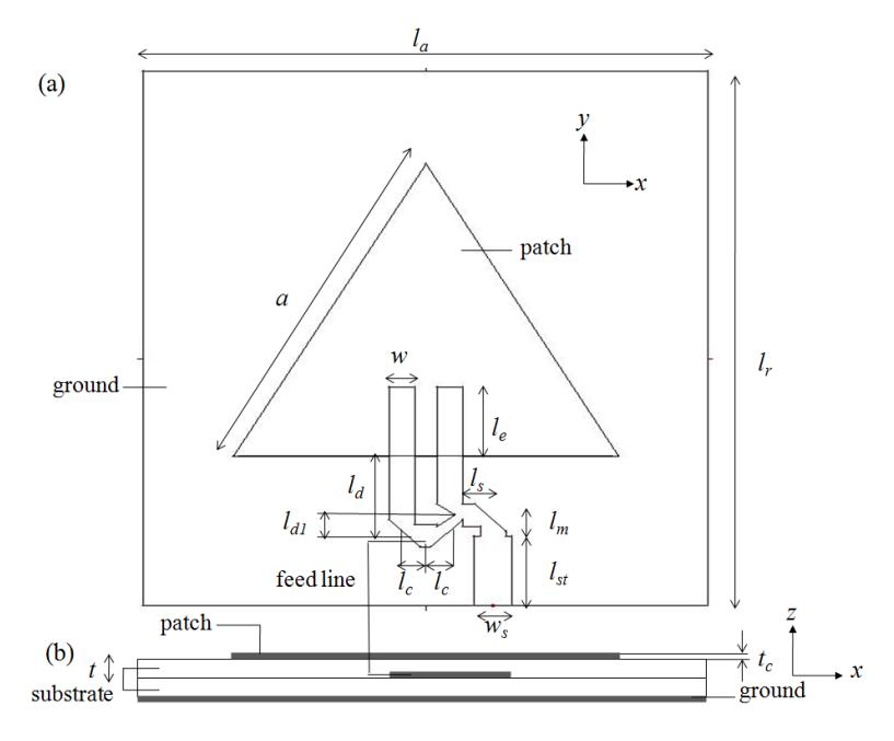
Figure 2 Configuration of equilateral triangular patch antenna with proximity coupled feed;
(a) top view and (b) side view
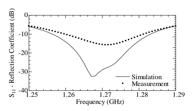
Figure 3 Reflection coefficient vs frequency
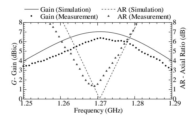
Figure 4 Gain and AR vs frequency at \(\theta\) (theta) angle = 0o
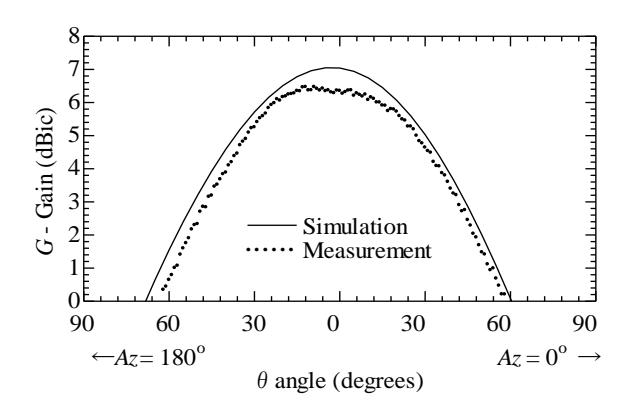
Figure 5 Gain vs theta angle (radiation pattern) in the theta plane (Az = 00 and 1800) (x - z plane) at f = 1.27 GHz
5 Conclusion
A circularly-polarized antenna has been developed for implementing antenna for circularly polarized synthetic aperture radar (CP-SAR) sensor operated in L-band. The design and optimization process was carried out using a MoM analysis software. The model was actually fabricated and measured in MRSL. Although the AR bandwidth is slightly smaller than the requirement for an airborne CP-SAR system, the present work has indicated that the goals can be met through a precise adjustment in the design and fabrication process in the near future.
6 References
- [1] Pokuls, R. , Uher, J. , and Pozar, D.M., September 1998. Dual -Frequency and Dual Polarization Microstrip Antennas for SAR Applications, IEEE Trans. Antenna Propagation, volume 46, no. 9, pp 1289-1296.
- [2] Garg, R. , Bhartia P. , Bahl I. , and Ittipiboon, A., 2001. Microstrip Antenna Design Handbook, Artech House, pp 720, 737.
- [3] Vetharatnam, G. Kuan, C.B, and Teik C.H., Microstrip Antenna for Airbone SAR Application http://www.remotesensing.gov.my/images/default/publication_3rdmicrowave/3rdmicr owave_paper5.pdf
- [4] Levine, E., Malamud, G., Shtrikman, S., and Treves, D., April 1989. A Study of Microstrip Array Antennas with the Feed Network, IEEE Trans. Antenna Propagation, volume 37, no. 4, pp 426-434.
7 Acknowledgement
The authors would like to thank Victor Wissan, Basari, Fauzan, Ilham A. and Zhang Jia -Yi for assisting in the antenna fabrication and measurement; the Japan Society for the Promotion of Science (JSPS) for Grant-in-Aid for Scientific Research - Young Scientist (A) (No. 19686025); Venture Business Laboratory - Chiba University for Project 10th Research Grant; National Institute of Information and Communication Technology (NICT) for International Research Collaboration Research Grant 2008, and other research grants that have supported this research.