
1 Introduction
The first time that chaos is found in history is in 1885 in Sweden. King Oscar II had a question about a 'three-body problem'. Three planets in space, which move in regard to each other by mutual gravitation forces. The person who would solve this question would receive a price. The same question, but then with two planets, was years before, solved by Newton. But this case is much more difficult [1].
A mathematic named Henri Poincare sends in an opinion of what he thinks is the answer. Moments before publication he noticed he has made a mistake. He explained that the problem in some way is unsolvable. The reason why this problem is unsolvable is that a very small difference in the start position or velocity can make a huge different in the final result. With this conclusion Poincare had the chaos principle [1].
Edward Lorenz has also an important place in the history of chaos. In the sixties he developed computer models. One of these models is of the earth atmosphere at the northern hemisphere. He made a lot of calculations to six decimal places. When he rounded off these numbers to three decimal places, the result was astonishing. In the beginning the old and new calculations coincided, but after some time the results were totally different. The conclusion is that the results of his calculation are strongly depended of the starting point. A small different in the start position can lead to large differences in the final result. When he repeated the process many times, by which he used the results as starting points. The differences in the results are plotted in a three dimensional graph, a butterfly appears then. This graph is also called the Lorenz attractor [1].
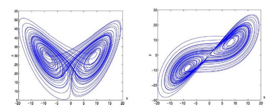
Figure 1 Lorenz Chaotic Attractor
The first observations of chaos in electronically circuits are in 1927. By Van der Pol and Van der Mark. They see it in nonlinear oscillators. In 1980 Ueda and Akamatsu find chaos in negative resistance oscillators. But the circuit of Chua is a bit more special. Because of its simplicity and university. Chua's circuit is dated from 1993 [2][3][4][5][6][7].
Chaos and chaotic systems have many fields of applications. One of the popular practical applications is secure communication. Synchronization of chaotic systems and chaos based secure communication has become an area of active research in recent years [8][9][10][11][12]. Chaotic signals depend very sensitively on initial conditions, have unpredictable features and noise like wideband spread spectrum. So, it can be used in various communication applications because of their features of masking and immunizing information against noise.
Figure 2 Chua's circuit models
Chaos-based secure communication systems have been alternative of the standard spreadspectrum systems, since they are able to spread the spectrum of the information signals and simultaneously encrypt the information signals with chaotic circuitry which is simple and inexpensive. Many researchers have investigated the implications of chaotic signals in communication systems [8][9][10][11][12].
This paper focuses on build, modified, and analyzed chaotic oscillator based Chua circuit, synchronization two identical chaotic attractor systems and its applications in signal masking communications.
2 Modeling The Circuit
2.1 Mathematical Formulation
Chua's circuit [2][3][4][5][6][7], shown in Figure 2, is a simple oscillator circuit which exhibits a variety of bifurcations and chaos. The circuit contains three linear energy-storage elements (an inductor and two capacitors), a linear resistor, and a single nonlinear resistor NR. Applying Kirchoff's law, the Chua's circuit is described by three differential equations:
\[C_{1} \frac{dv_{C1}}{dt} = G(v_{C2} - v_{C1}) - g(v_{C1})\] \[C_{2} \frac{dv_{C2}}{dt} = G(v_{C1} - v_{C2}) + i_{L}\] \[L \frac{di_{L}}{dt} = -v_{C2}\] (1)
where
\(v_{C1}\) = the voltage over the capacitor \(C_1\),
\(v_{C2}\) = the voltage over the capacitor \(C_2\),
\(i_{I}\) = the current through the inductance,
C = capacitance the capacitor.
L = inductance the inductor, and
G = conductance the linear resistor.
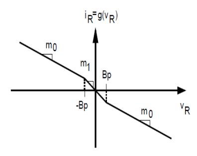
Figure 3 Chua's nonlinear resistor function
\(g(v_{Cl})\) is the non-linear voltage-current characteristic of the nonlinear resistor. Shown in Figure 3, can be written as
\[g(v_{C1}) = g(v_R) = m_0 v_R + \frac{1}{2} (m_1 - m_0) [v_R + B_P - v_R - B_P]\](2)
where \(m_1\) and \(m_0\) are the slopes in the inner and outer regions, respectively, and \(\pm B_P\) denote the breakpoints. The resistor R is a potentiometer and is used to tune the oscillator over a range of bifurcation values.
3 Numerical Simulation and Circuit Implementation
The values of the two capacitors, inductor and resistor are chosen from the computer simulations confirmed by Matsumoto [2]. \(E_{sat}\) is the saturation voltage of the operational amplifier. It is determined by the power supplies and the internal structure of the op amps. The nonlinear resistor consists of two negative resistors connected in parallel. We choose \(R_1\) large enough so that the op amp is not loaded, say around \(220\Omega\). \(R_2\) is chosen to be equal to \(R_1\) so as to make the analysis simple. The break points (boundary points for the attractor) are calculated such that, the attractor (the state in which the system settles) remains in the negative resistance region (the region in which the current is inversely proportional to the voltage) so that the attractor is bounded see Figure 5. The detail design of the nonlinear resistor is given by Kennedy [3].
The constant \(m_0\), \(m_1\), and \(B_p\) can be easily computed [3]. The complete implementation of the Chua's circuit is shown in Figure 7.
\[\left(m_{1} = -\frac{R_{2}}{R_{1}R_{3}} - \frac{R_{5}}{R_{4}R_{6}}, m_{0} = -\frac{R_{2}}{R_{1}R_{3}} + \frac{1}{R_{4}}, B_{P1} = \frac{R_{3}}{R_{2} + R_{3}} E_{sat}, B_{P2} = \frac{R_{6}}{R_{5} + R_{6}} E_{sat}\right)\](3)
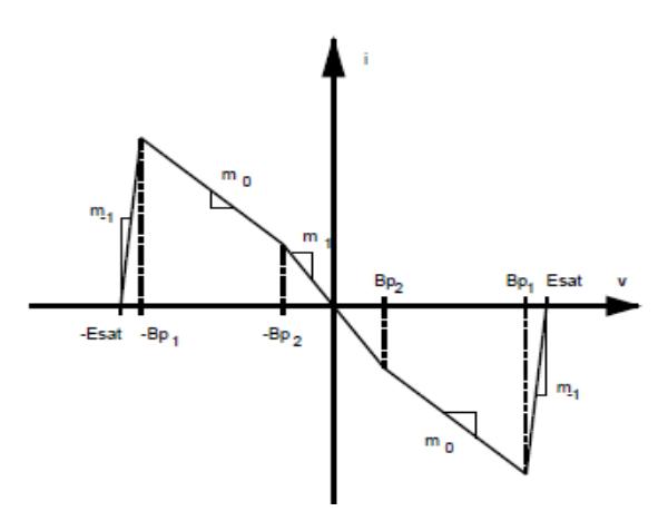
Figure 4 Chua's nonlinear resistor function with two parallel op-amp
3.1 Numerical Simulations
In this section, we present numerical simulation to illustrate the dynamical behavior of Chua's circuit from system [1]. For numerical simulation of chaotic systems defined by a set of differential equations such as Chua's circuit, different integration techniques can be used in simulation tools. In the MATLAB numerical simulations, ODE45 solver yielding a fourth-order Runge-Kutta integration solution has been used.
According to these numerical simulations, the circuit's chaotic dynamics and double-scroll attractors are shown in Figure 5. These numerical solutions can be compared with the former results obtained from MultiSIM simulations and laboratory experiments presented in the next section. For showing the dynamics of the system [1] change, the parameter set given as a fixed parameters, see Table 1 and R as a varied parameters.
Table 1 Chua's circuit parameters
| Element | Description | Value | Tolerance |
|---|---|---|---|
| R1 | Resistor | 220 Ω | 5% |
| R2 | Resistor | 220 Ω | 5% |
| R3 | Resistor | 2.2kΩ | 5% |
| R4 | Resistor | 22kΩ | 5% |
| R5 | Resistor | 22k Ω | 5% |
| R6 | Resistor | 3.3k Ω | 5% |
| C1 | Capacitor | 10nF | 5% |
| C2 | Capacitor | 100nF | 5% |
| L | Inductor | 18mH | 10% |
| R | Potentiometer | varied | 5% |
| Esat | Power Supply Op amp | 9 V | |
| U1A | TL082CD | ||
| U1B | TL082CD |
By reducing the variable resistor R in Figure 1 from 2 kΩ towards zero, Chua's circuit exhibits a sequence of bifurcations from limit cycle equilibrium through a Hopf bifurcation and period-doubling sequence to a Rossler-type attractor, from a Rossler-type attractor changes to the Double Scroll strange attractor, and from the Double Scroll strange attractor changes to large limit cycle as illustrated in Figure 6.
Notice that varying R in this way causes the size of the attractors to change: the period -one orbit is large, period-two is smaller, the Rossler-type attractor is smaller again, and the Double Scroll shrinks considerably before it dies.
0.005
0.01
Figure 5 Chua's Attractor with R = 1:8K; (a) Phase Portrait; (b) Time Series
(b)
0.02
0.025
0.03
0.035
0.04
0.015
Figure 6 Numerical Simulation: Typical R bifurcation sequence in Chua's circuit (component values as in the table 1). (a) R = 2:00k; limit cycle (b) R = 1:95k, Rossler-type attractor; (c) R = 1:9k, Double Scroll attractor; (d) R = 1:85k, Double Scroll attractor; (e) R = 1:7k, Double Scroll attractor; (f) R = 1:65k, large limit cycle
3.2 MultiSIM Circuit Simulations
The complete implementation of the Chua's circuit design using MultiSIM software is shown in Figure 7. The function of nonlinear resistor as see in Figure 2, are implemented with the analog operational amplifier such as TL082CD. The supplies of TL082CD are \(\pm 9V\).
Figure 7 Implementation of Chua's circuit
The results of MultiSIM simulation show the phase portrait of the probed signal in Figure 8, 9, and 10.
Figure 8 MultiSIM simulation with R = 1:8K: Phase Portrait VC2 versus VC1
Figure 9 MultiSIM simulation: Chaotic Time series VC1
For showing Bifurcation and the dynamics of the system Chua' system change, the parameter set given as a fixed parameters (see Table 1 and Figure 7) and R as a varied parameters. Figure 10 shows bifurcation phase portraits Chua's circuit attractor.
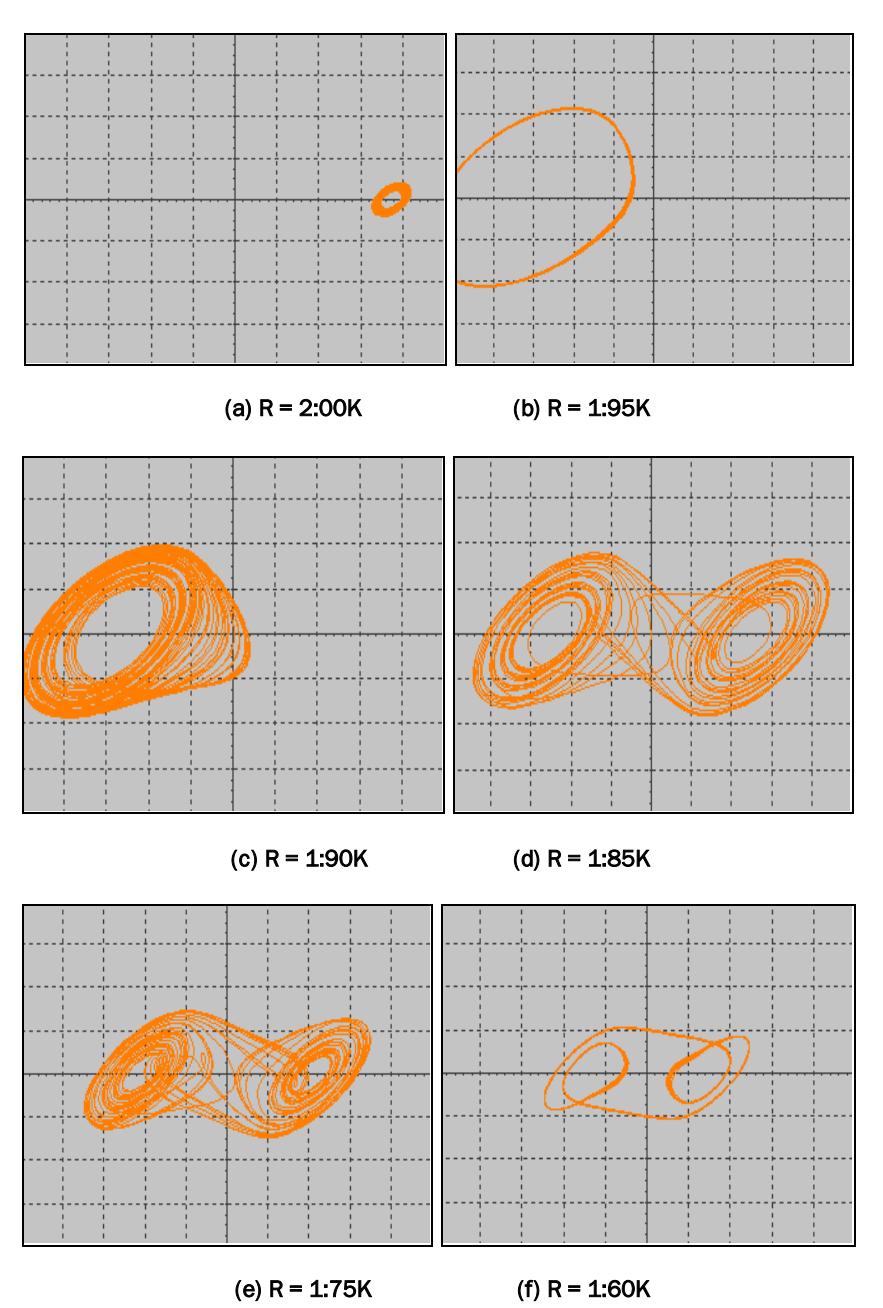
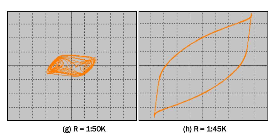
Figure 10 MultiSIM circuit Simulation: Typical R bifurcation sequence in Chua's circuit
3.3 Experimental Results
The experimental electronic circuit hardware realization of the Chua's circuit is shown in Figure 11. Oscilloscope outputs of Chua's circuit given by Phase portraits in Figure 12, and the typical R bifurcation in Figure 13.
Figure 11 Chua's circuit PCB implementation.
Figure 12 Experimental result: chaotic double scroll attractor phase portrait VC2 versus VC1
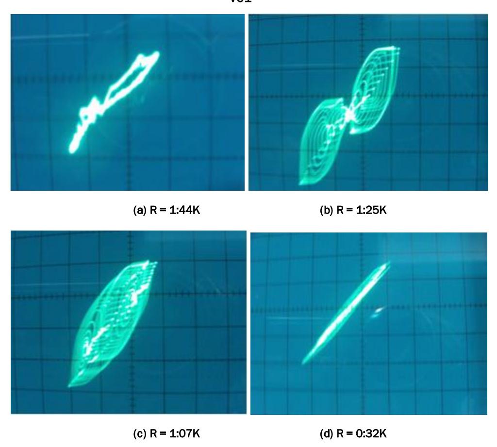
Figure 13 Experimental result: Typical R bifurcation sequence in Chua's circuit
By comparing Figure 6, 10, and 13, it can be concluded that a good qualitative agreement between the numerical integration of (1) using Matlab, the circuits simulation using MultiSIM, and the experimental results from a hardware electrical circuit realization is obtained, including Typical R bifurcation, and the existance "double scroll attractor", which can be observed in a very small region of control parameter R.
A different quantitative results between numerical method, circuit simulation, and laboratory experiment is caused by a small difference in initial condition of each method. For chaotic system, a small different in the start position can lead to large differences in the final result [1].
4 Synchronization of the Chua Attractor
Synchronization between chaotic systems has received considerable attention and led to communication applications. With coupling and synchronizing identical chaotic systems methods, a message signal sent by a transmitter system can be reproduced at a receiver under the influence of a single chaotic signal through synchronization. This paper presents the study of numerical simulation of chaos synchronization for chaotic Chua attractor. Drive system and response system were constructed.
Synchronization of chaotic motions among coupled dynamical systems is an important generalization ion from the phenomenon of the synchronization of linear system, which is useful and indispensable in communications. The idea of the methods is to reproduce all the signals at the receiver under the influence of a single chaotic signal from the driver. Therefore, chaos synchronization provides potential applications to communications and signal processing [8][9][10][11][12]. However, to build secure communications system, some other important factors, need to be considered. Simulations of synchronization of Chua system are presented as shown in Figure 14.
The control value R of the two system are different, the control value R of the drive system is 1.85 kohm, the control value R of the response system is 1.75 kohm. Simulation results show that the two systems synchronize well. Figure 14 shows the circuit schematic for implementing the Synchronization of Chua system. We use TL082CD op-amps, appropriate valued resistors, inductor and capacitors for MultiSIM® simulations. Figure 14 also shows MultiSIM® simulation results of this circuit.
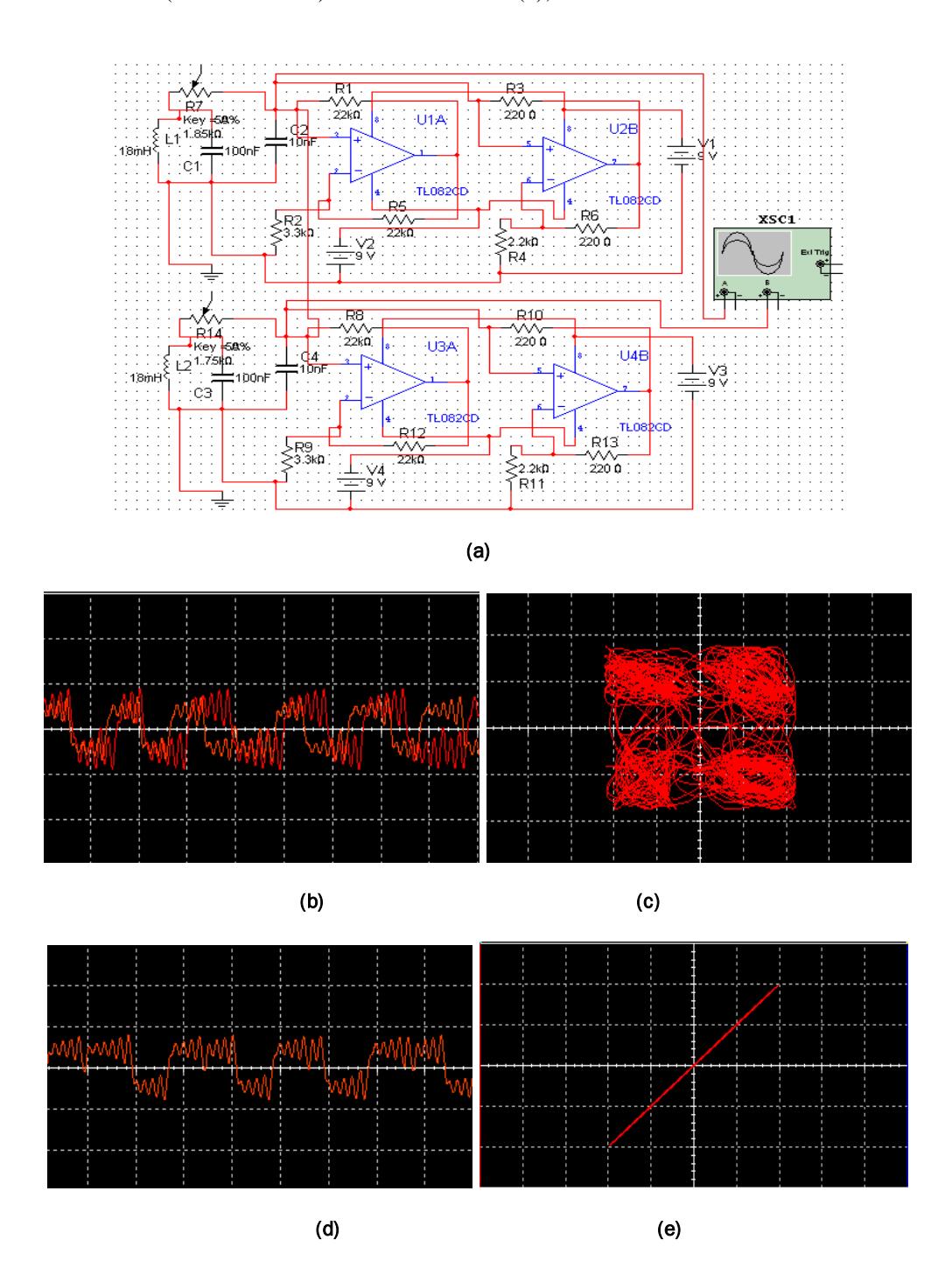
Figure 14 MultiSIM® Circuit and simulations: (a) Synchronization of Chua's attractor Circuit; (b) Drive and response system chaotic signals before synchronization ; (c) The phase portrait of unsynchronized case; (d) Drive and response system chaotic signals after synchronization; (e) X-Xr Synchronization
5 Application for Secure Communication Systems
Due to the fact that output signal can recover input signal, it indicates that it is possible to implement secure communication for a chaotic system. The presence of the chaotic signal between the transmitter and receiver has proposed the use of chaos in secure communication systems. The design of these systems depends as we explained earlier on the self synchronization property of the Chua attractor. Transmitter and receiver systems are identical except for their control value R, in which the transmitter system is 1.85 kohm and the receiver system is 1.75 kohm as shown in Figure 14.
It is necessary to make sure the parameters of transmitter and receiver are identical for implementing the chaotic masking communication [8][9][10][11][12]. In this masking scheme, a low-level message signal is added to the synchronizing driving chaotic signal in order to regenerate a clean driving signal at the receiver. Thus, the message has been perfectly recovered by using the signal masking approach through synchronization in the Chua attractor. Computer simulation results have shown that the performance of Chua attractor in chaotic masking and message recovery.
The square wave signal is added to the generated chaotic x signal, and the S(t) = x + i(t) is feed into the receiver. The chaotic x signal is regenerated allowing a single subtraction to retrieve the transmitted signal, [x+i(t)]-xr = i'(t), If x = xr. Figure 15 shows the circuit schematic for implementing the Chua attractor's Chaotic Masking Communication. Figure 16 shows MultiSIM® simulation results of this Chaotic Masking Circuit.
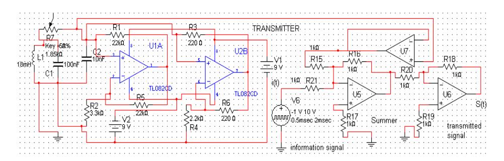
(a) Transmitter circuit
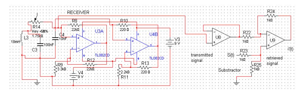
(b) Receiver circuit
Figure 15 Chua attractor chaotic masking communication circuit
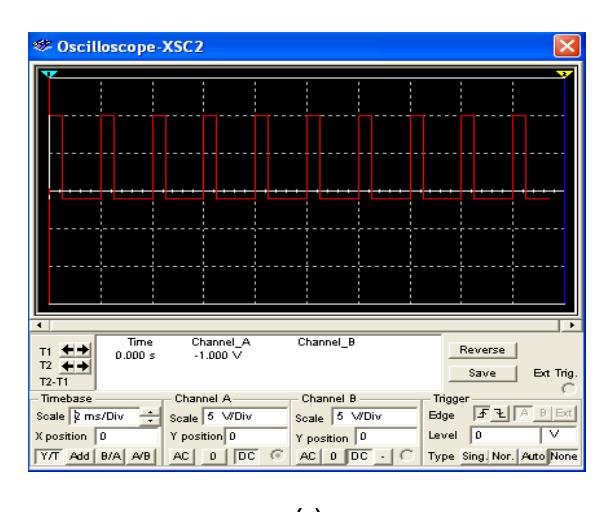
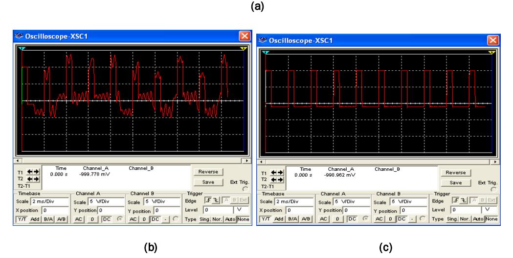
Figure 16 MultiSIM® outputs of Chua's attractor Masking Communication Circuit: (a) Information signal i(t); (b) chaotic masking transmitted signal S(t); (c) retrieved signal i'(t)
6 Conclusions
This paper focuses on the chaotic oscillator circuit and the identical synchronization of the Chua's attractor and its applications in signal masking communications. In this paper, Chua's chaotic circuit system is studied in detail by varying mostly the control parameter R . The system has rich chaotic dynamics behaviors. The resulting chaotic system is not only demonstrated by numerical simulation but also implemented via an electronic circuit simulation and tested experimentally in laboratory, showing very good qualitative agreement with the simulation results. We have demonstrated in simulations that chaos can be synchronized and applied to secure communications. We suggest that this phenomenon of chaos synchronism may serve as the basis for little known Chua attractor to achieve secure communication. Chaos synchronization and chaos masking were realized using MultiSIM® programs.
7 References
- [1] Alligood, K. T., Sauer, T. D. & Yorke, J. A., Chaos: An Introduction to Dynamical Systems. Springer-Verlag, New York, 1996.
- [2] Matsumoto, T., A chaotic attractor from Chua's circuit. IEEE Trans. Circuits Syst., CAS 31(12):1055|1058, 1984.
- [3] Kennedy, M.P., Robust Op Amp Implementation of Chua's Circuit, Frequenz Vol.46, no.3-4, pp.66-80, 1992.
- [4] Kennedy, M.P., Three Steps to chaos-Part I: Evolution, IEEE Transaction on Circuits and Systems, Vol.40, no.10, pp.640-656, October 1993.
- [5] Kennedy, M.P., Three Steps to chaos-Part II: A Chua's Circuit Primer, IEEE Transaction on Circuits and Systems, Vol.40, no.10, pp.657-674, October 1993.
- [6] Chua, L.O. et al, A Universal Circuit for Studying and Generating Chaos-Part I : Routes to Chaos, IEEE Transaction on Circuit and Systems, Vol.40, no10, pp.732-744, October 1993.
- [7] Chua, L.O. et al, A Universal Circuit for Studying and Generating Chaos-Part II : Strange Attractors, IEEE Transaction on Circuit and Systems, Vol.40, no10, pp.745- 762, October 1993.
- [8] Mulukutla, M. & Aissi, C., Implementation of the Chua's circuit and its application, Proceedings of the 2002 ASEE Gulf-Southwest Annual Conference, The University of Louisiana at Lafayette, Session IVB5, March 20-22, 2002.
- [9] Feng, J.C., & Tse, C.K. Reconstruction of Chaotic Signals with Applications to Chaos - Based Communications, Tsinghua University Press dan World Scientific Publishing Co. Pte. Ltd., 2007.
- [10] Pehlivan, I. & Uyaroglu, Y., Rikitake Attractor and It's Synchronization Application for Secure Communication Systems, Journal of Applied Sciences 7(2):232-236, 2007.
- [11] Lee, T.H. & Park, J.H., Generalized Functional Projective Synchronization of Chen-Lee Chaotic Systems and Its Circuit Implementation, International Journal of the Physical Sciences Vol. 5(7), pp. 1183-1190, July 2010.
- [12] Pehlivan, I., Uyaroglu, Y., & Yogun, M., Chaotic Oscillator Design and Realizations of the Rucklidge Attractor and Its Synchronization and Masking Simulations, Scientific Research and Essays Vol. 5(16), pp. 2210-2219, 18 August, 2010.