
Abstrak
Teknologi pendukung lansia adalah bidang yang terus berkembang karena terus ditemukannya kebutuhan dan teknologi baru. Studi ini menyangkut kebutuhan lansia dalam mengambil benda di lantai, yang sering menyakitkan atau sulit bagi lansia dengan sakit punggung. Saat ini, belum ada sistem bantuan demikian tersedia di pasaran. Studi ini bertujuan untuk mengembangkan tongkat yang terintegrasi cakar derek untuk membantu mengambil benda tanpa membungkuk, sehingga meningkatkan mobilitas dan mengurangi risiko jatuh. Dengan mengintegrasikan cakar dan tongkat, perangkat yang dikembangkan akan membantu kehidupan sehari-hari lansia tanpa alat tambahan. Tiga konsep rancangan, Dengan memanfaatkan bagian-bagian printer 3D yang didaur ulang, dievaluasi berdasarkan performa, kesederhanaan, dan biaya, mekanisme winch kabel akhirnya dipilih. Analisis tegangan dan kelelahan menggunakan SolidWorks memastikan keamanan, dengan rakitan cakar menunjukkan tegangan maksimum sebesar 7,238×106 Pa dan faktor keamanan sebesar 4,8, serta umur kelelahan sebesar 691.507 siklus. Produk ini diproduksi menggunakan material PLA dengan kepadatan 50% dan pola tri-heksagonal. Sistem mekatronik, yang terdiri dari Arduino UNO, motor DC, modul H-Bridge L298N, dan sensor, memungkinkan kontrol cakar yang presisi. Produk akhir ini meningkatkan kemandirian dan mobilitas pengguna lansia, menawarkan solusi yang ergonomis dan ramah pengguna.
Kata Kunci: alat bantu jalan; lansia; mobilitas; tongkat jalan; desain teknik.
Makalah diterima 2 Maret 2025 – makalah direvisi 24 Maret 2025– disetujui 17 April 2025
Karya ini adalah naskah akses terbuka dengan lisensi CC BY-SA.
1 Introduction
Elderly people often have reduced capacity to perform many activities they were once able to do when they were younger, especially in their mobility. A study by Maresova et al. stated that most 80-year-olds and around onethird of 70-year-olds report having limited mobility in their dwellings and adjacent areas [1]. This mobility loss or restriction is a complicated, multifaced process that degrades older people's quality of life and raises overall mortality by increasing their risk of falls, accidents, and hospitalizations. Another study also stated that people with chronic mobility impairments find it more difficult to perform daily activities [2]. Moreover, transportationrelated obstacles also affect older people with mobility disabilities (PAwMD), which might limit their capacity to fully engage in society [3]. To overcome these difficulties, elderly people often use walking aids to facilitate their activities. One of the most popular walking aids is a walking stick.
The walking stick has become the most popular walking aid because it is widely accepted in society and is simple to use. A study found that for some elderly individuals, it has been a life-saving tool, especially while they are on the go [4]. The walking stick can help them avoid falling due to their weak muscles [5], deteriorating vision and hearing, and the influence of external obstacles. Extensive research has been conducted on walking sticks, focusing on aspects such as their overall mass rating and the weight capacity they can support. Another study reported that a sturdy and elegant cane can support weights up to 100 kg [6], aligning with CDC data that the average 60-plus man weighs nearly 89 kg and a woman over 75 kg [7]. For its overall mass, it is important to consider that an elderly person can lift, on average, 20.2 kg for men and 13.2 kg for women in four consecutive repetitions from the hip to the shoulder [8].
Many innovations have been made to walking sticks to better accommodate the elderly, such as adding a fall alarm [9], GPS [10], a health monitoring system [11], and even a heart attack detection system [12]. However, no innovations have been made to help the elderly grab things from the ground without needing to bend down. For the elderly, bending down is challenging due to weaker joints and back muscles [13], [14]. Additionally, bending down can affect balance, leading to falls [15]. Walking sticks combined with a grabbing tool exist, but users need to sacrifice their balance to reach for the item picked up by the tool. An alternative would be to carry both a grabbing tool and a walking stick separately, which would be a hassle for the elderly.
This study aims to find a solution that would help the elderly grab items from the ground without needing to bend down and sacrifice their balance. This can be done by integrating a grabbing tool into existing three-legged walking sticks, aiming to provide users with enhanced stability, balance, and convenience, thus improving their overall mobility and independence. To provide the functionality of transporting the item from the ground to the waist level, a vertical movement mechanism is needed. This study examines three possible methods for the vertical movement system: the rack and pinion system, the cable winch system, and the pulley system. Each mechanism was evaluated based on its effectiveness, alignment with project goals, and overall performance. The goal is to choose a method that enhances performance based on the respective project objectives.
The manufacturing process for the rack and pinion is more challenging due to the need for precise assembly with strict tolerances [16]. To ensure the functioning of the pulley assembly, it is necessary to maintain tension in the belt. There are two methods to do this task. One can achieve optimal results by utilizing precisely matched components or employing a tensioner. Both of them present a formidable challenge. Conversely, a cable winch does not require precise tolerances or closely fitting components [17], in comparison to another device.
For reliability, the rack and pinion mechanism is superior to the other mechanisms due to it not relying on the tension of the belt, nor the condition of the cable [18]. The pulley mechanism's belt tension would need to be adjusted periodically to ensure the vertical movement mechanism works properly. On the other hand, the cable winch mechanism depends on the quality of the cable itself, it will eventually need to be changed when it is worn out [19].
It is crucial for designing remote manipulators that accurately mimic human hand movements, prioritizing safety, especially for the elderly during daily tasks. Through precise measurements using advanced stereo vision cameras, a study by K. Cieślik and M. J. Łopatka, reveals that maximum velocity remains around 1 m/s, irrespective of direction [20].
2 Methodology
This study follows the principles in Shigley's Mechanical Engineering Design [21] as a framework for developing the crane claw-integrated walking stick, which include conceptual design, synthesis, and evaluation procedures.
2.1 Conceptual Design
The problem in this study is to design a tool to help elderly people to pick up an object from the floor. Elderly people who need help pick up an object from the floor is usually experiencing back pain, having a symptom of Parkinson, or other disease related to controlling the upper body. Furthermore, elderly people with these situations are usually in need of a cane or walking stick to walk. In this study, we aim to utilize a regular walking stick which is used to help the elderly to walk and modify it so that it can be used to pick up an object from the floor. Any other base design as the alternative is not viable since those designs will create a new object altogether.
The walking stick must be sturdy, lightweight, and easy to use to provide support and assist with picking up objects. It features a grappling hook claw at the lower end, operated by a pulley with a belt, a single rope, or a pinion and rack gear system powered by a stepper motor. An ergonomic control system near the handle enables operation without compromising balance, ensuring functionality and independence for the elderly.
2.2 Synthesis Procedure
Initially, three designs were proposed, each employing different vertical movement mechanisms to facilitate the walking stick modification. Figure 1 depicts the first design utilizing a rack and pinion mechanism, motorized pulley mechanism, and cable winch mechanism. These mechanisms are commonly used mechanism, and we purposefully pick these so that we do not invent a new mechanism which would result in more design cost.
Figure 1. Walking stick modification sketch with a (a) rack and pinion, (b) motorized pulley, and (c) cable winch mechanism.
Benchmarking was conducted to determine the optimal vertical movement mechanism, using Design 1 (rack and pinion) as a reference for evaluating Designs 2 and 3. The weights of each criterion for benchmarking is given in Table 1. Design 3, featuring a cable winch mechanism, was identified as the best option based on predefined criteria (see Table 2 for the benchmarking results). However, budget constraints necessitated a costeffective alternative, leading to the repurposing of parts from a decommissioned 3D printer. The final design integrates the strengths of all initial concepts, combining the structural rigidity of the rack and pinion, the simplicity of the cable winch, and the functionality of the motorized pulley, to meet the project's objectives.
Table 1. Weights of each criterion for benchmarking.
| Primary | 100 | |
|---|---|---|
| Has a height of 95 cm | 20 | |
| The moving body of the vertical movement mechanism weighs less than 1 kg | 20 | |
| Able to lift common household objects weighing up to 1 kg | 15 | |
| The device has a straightforward interface for ease of use | 15 | |
| The entirety of the modification weighs less than 2 kg | 15 | |
| Uses common materials and easy assembly | 15 | |
| Secondary | 20 | |
| Water-resistant | 10 | |
| Able to be operated for 10 cycles on one charge | 10 | |
| Tertiary | 10 | |
| The height of the modification can be adjusted to suit the preference of the user | 5 | |
| Able to be mass-manufactured | 5 | |
| Total | 130 | 130 |
https://doi.org/10.5614/joki.2025.17.1.3 E-ISSN: 2460-6340
Table 2. Benchmarking
| Criteria | Weight | Design 1 | Design 1 Multiplied | Design 2 | Design 2 Multiplied | Design 3 | Design 3 Multiplied |
|---|---|---|---|---|---|---|---|
| Has a height of 95 cm | 20 | 0 | 0 | 0 | 0 | 0 | 0 |
| The moving body of the vertical movement mechanism weighs less than 1 kg | 20 | 0 | 0 | 1 | 20 | 1 | 20 |
| Able to lift common household objects weighing up to 1 kg | 15 | 0 | 0 | 0 | 0 | 0 | 0 |
| Straightforward interface | 15 | 0 | 0 | 0 | 0 | 0 | 0 |
| The entirety of the modification weighs less than 2 kg | 15 | 0 | 0 | 0 | 0 | 0 | 0 |
| Uses common materials and easy assembly | 15 | 0 | 0 | 0 | 0 | 0 | 0 |
| Water-resistant | 10 | 0 | 0 | 0 | 0 | 0 | 0 |
| Able to be operated for 10 cycles on one charge | 10 | 0 | 0 | 0 | 0 | 0 | 0 |
| Adjustable height | 5 | 0 | 0 | -1 | -5 | 0 | 0 |
| Able to be mass-manufactured | 5 | 0 | 0 | 0 | 0 | 0 | 0 |
| Total | Design 1 | 0 | Design 2 | 15 | Design 3 | 20 |
2.3 Evaluation Procedure
To efficiently manage the design process and enhance collaboration, the Computer-Aided Design (CAD) components are structured into three distinct parts: mounting and cable rollers, electrical box, and claw assembly. Please see figures 2, 3, and 4 for these CAD components.
Figure 2. 3D Isometric view of the (a) Upper mounting, (b) Cable roller, (c) Bottom mounting, and (d) Cable roller adapter.
Figure 3. 3D Isometric view of the (a) Electric box, (b) Its cover, (c) Battery box, and (d) Its cover.
(a) (b) (c) (d) (e)
Figure 4. 3D Isometric view of claw assembly: (a) Part 1, (b) Part 2, (c) Part 3, (d) Part 4, and (e) Part 5.
The evaluation procedure will include stress analysis of the top mounting, lower mounting, and claw assembly. It will consider design factors, which can be calculated using the given formula.
\[n_d = \frac{S}{n_d^m} \tag{1}\]
E-ISSN: 2460-6340
\[n_d = \frac{Strength}{Stress} = \frac{S}{\sigma} \tag{2}\]
\[\underline{n_d} = \frac{S}{\sigma} \tag{3}\]
We assume that the maximum carrying capacity is 1 kg, and we also assume a 20% uncertainty due to everyday item variations. The failure load has a 75% uncertainty due to 3D printing quality variability. The design factor is calculated using the following formula:
\[n_d = \frac{Loss \ of \ function \ load \ is \ minimum}{Load \ is \ maximum} \tag{4}\] and the result is \(n_d=0.21\). To make them equal, we take the inverse to get a design factor of 0.48. By comparing the stress analysis to the design factor, the worst-case scenario is identified, followed by a fatigue analysis in critical areas.
2.4 Prototyping
2.4.1 Manufacturing Process
Fused deposition modeling (FDM) using Sunly PLA+ was selected as the manufacturing method for the project's components, including the assembly, DC motor mounting, and winch attachment. The Anycubic Kobra 2 printer was used, with designs created in SolidWorks and converted to Gcode using the Anycubic slicer. Printing parameters included a 0.2mm layer height, 50% infill, a bed temperature of 65 °C, and an extruder temperature of 205 °C, utilizing a tri-hexagonal pattern to ensure structural integrity.
2.4.2 Mechatronics
To control the vertical movement of the claw mechanism, several components were utilized. These include an Arduino UNO, a 12V 250 RPM DC motor, an 11.1V LiPo battery, an H-Bridge L298N module, resistors, jumper cables, an ON/OFF switch, a joystick, a potentiometer, and a tilt sensor. The arduino code and wiring mechanism can be seen in Figure 5.
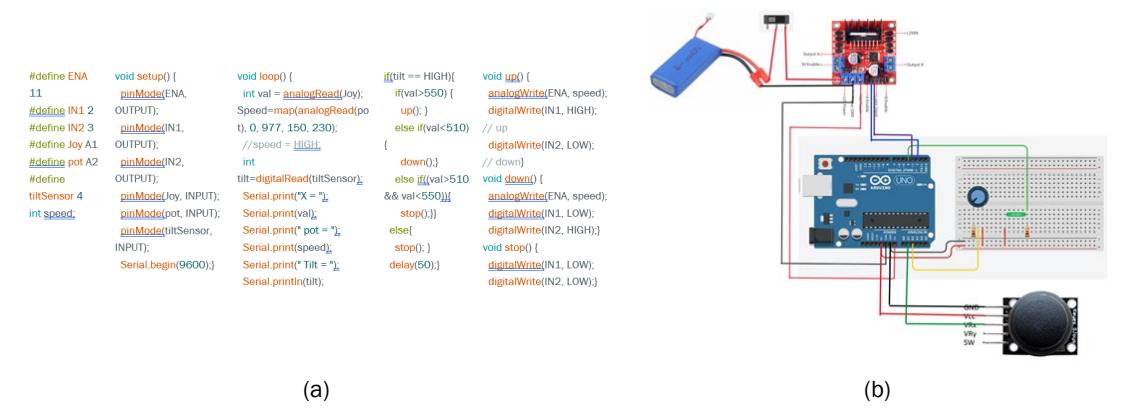
Figure 5. Mechatronics, (a) Arduino code of the mechanism and (b) wiring diagram.
The program utilizes an H-Bridge L298N Module to control both the speed and direction of the 12V DC motor while also serving as a step-down module to power the Arduino UNO. A jumper is placed on the H-Bridge's 5V regulator, converting its 5V pin from input to output, which is then connected to the Vin pin of the Arduino. The potentiometer adjusts the motor speed via PWM, with its range determined through trial and error to ensure sufficient torque for lifting the claw. The joystick controls the motor's direction. For safety, a tilt sensor is integrated into the circuit to mitigate unintended movements.
2.4.3 Assembly
The assembly of this project was carefully executed, primarily using nuts and bolts, with some components secured using a glue gun for added stability. After assembling all components and programming the mechatronic parts, an extensive testing phase was conducted to evaluate the project's functionality under real-world conditions. The testing produced favorable results, confirming the successful realization of the project's objectives.
3 Results and Discussion
3.1 Stress Analysis
The manual calculations in this project employ several simplifications. These are then followed by the use of SolidWorks, a Finite Element Analysis (FEA) software. The dual approach allows for cross-validation of the outcomes, ensuring the validity, reliability, and practicality of the designs. The primary objective in stress analysis was to determine the safety factor of three main parts: the Upper Mounting, Lower Mounting, and the Claw Assembly. All parts were made from PLA with a 50% density and a tri-hexagonal pattern, which have the following material's properties are: Young's modulus 2.72±0.14 GPa, yield strength 27.6±1.11 MPa, and ultimate strength 30.6±1.23 Mpa [21].
3.1.1 Upper Mounting
The Upper Mounting part is subjected to uniaxial loading, primarily where the DC motor is mounted. When loaded, it supports the weight of the DC motor itself, the claw, the load, the winch, and the bottom attachment. This part is designed to be the last to break as it holds the controls and the assembly. Figure 6 shows the drawings related to Upper Mounting subjected to uniaxial loading.
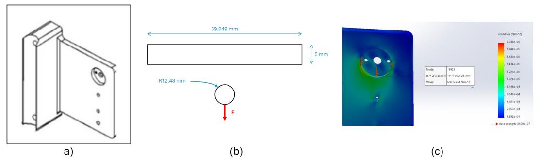
Figure 6. Upper Mounting: (a) 3D schematic, (b) FBD and arc cross-sectional area, and (c) FEA max stress.
Based on the available data, the cross-sectional area (the arc) is calculated to be 39.049 mm<sup>2</sup>.
The following formula is used to calculate the maximum stress of top mounting:
\[\sigma = \frac{F}{A} \tag{5}\] where \(F = W_{dc} + W_{claw} + W_{load} + W_{winch} + W_{bottom \, attachment}\) and \(A = arc \times thickness\). The result is \(\sigma = 72145.253 \, Pa\). To verify the FEA results, the error between analytical and FEA results should be calculated. Any error below 20% is acceptable as the analytical results give the ballpark of the results. Following is the %error of the calculation:
%error = \[\frac{(72145.253) - (6.971 \times 10^4)}{72145.253} \times 100\% = 3.38\%\]
\(\% error = \frac{(72145.253) - (6.971 \times 10^4)}{72145.253} \times 100\% = 3.38\%\) Based on the percentage error, the safety factor, n = \(\frac{s_y}{\sigma}\), with \(S_y = 27.6\) MPa and \(\sigma = 0.072\) MPa is 383.33. The safety factor of 383.33 shows that the product is safe to use within the design load.
3.1.2 Lower Mounting
The Lower Mounting functions as a cantilever beam within the assembly, primarily experiencing loading during the upward movement of the overall structure. As the assembly ascends, the Lower Mounting undergoes bending stresses due to these combined forces. Figure 7 provides drawings related to this component.
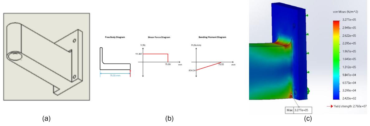
Figure 7. Lower Mounting: (a) 3D schematic, (b) FBD, SFD, BMD & fillet stress concentration factor, and (c) FEA max stress. For a cantilever beam, stress concentration can be calculated using Shigley's method [13]. For d=35 mm, t=17 mm, D=60 mm, and r=5 mm, we have \(\frac{D}{d}=1.7\) and \(\frac{r}{d}=0.143\). Thus, referring to Figure A-15-6 from [13], the following stress concentration factor is \(K_t = 1.62\).
To calculate the stress of the structure using analytical approach, we use the following formula:
\[\sigma' = \frac{Mc}{I} \tag{6}\]
Where \(c = \frac{d}{2} = 17.55 \, mm\), \(I = \frac{1}{12} wt^3 = 60739.583 \, mm^4\), and \(M = 854.24 \, Nmm\). Thus, \(\sigma' = 0.246 \, MPa\).
To verify the FEA results, the error should be calculated. Any error that is below 20% is acceptable.
\[\%Error = \frac{(0.399) - (0.3277)}{0.399} \times 100\% = 17.87\%\]
Since the error is less than 20%, it is appropriate to use the value derived from the FEA to calculate the safety factor. The safety factor can then be calculated as follows:
\[n = \frac{S_{ut}}{\sigma} = \frac{30.6}{0.3277} = 93.38\]
With this high safety factor, the stress calculation error becomes negligible, and we can guarantee the safety of the components.
E-ISSN: 2460-6340
3.1.3 Claw Assembly
The claw assembly is expected to fail first, thus representing the most critical point of failure. To streamline this process, the Upper Mounting of the Claw Assembly is selected as a representative sample for the entire assembly. The Upper Mounting is modelled as a cantilever beam to simulate the behavior of the five individual beams present on the part. Thus, the beam width and thickness become 15 mm and 3 mm, respectively. Consequently, the force applied to this simulated beam was increased to five times the original load, reflecting the cumulative effect of the multiple beams. The moment of area can also be calculated as follows:
\[I = \frac{1}{12}w^3t = \frac{1}{12}(15^3)(3) = 843.75 \text{ mm}^4\]
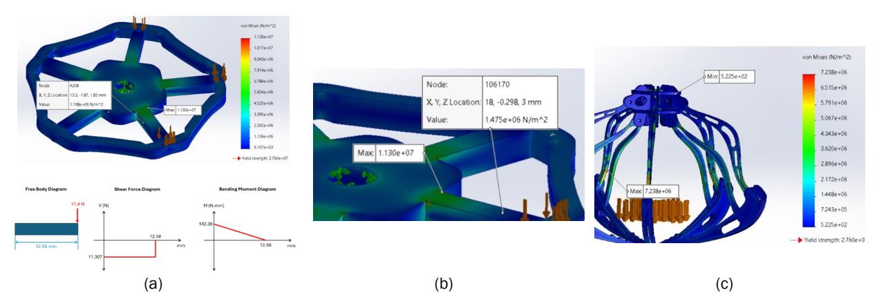
Figure 8. Claw assembly: (a) 3D loading diagram, FBD, SFD, & BMD, (b) Upper FEA max stress, and (c) FEA max stress.
As the load is 5 times its original load. Thus, the calculation for stress can now be done as follows:
\[\sigma = \frac{\mathit{Mc}}{\mathit{I}} = \frac{(5 \times 11.4 \times 12.59) \times 1.5}{843.75} = 1.28 \, \mathit{MPa}\] To verify this FEA, the error should be calculated. The manual calculation yields the stress on the surface and neglects stress concentration in filets.
\[\%Error = \frac{1.28 - 1.475}{1.28} \times 100\% = 15.2\%\]
As the percentage error falls within the acceptable range, the safety factor can be calculated as follows:
\[n = \frac{S_y}{\sigma} = \frac{27.6}{7.238} = 3.81\]
\(n=\frac{S_y}{\sigma}=\frac{27.6}{7.238}=3.81\) The safety factor of 3.81 indicates the design can withstand nearly four times the intended 1 kg load.
3.2 Fatigue Analysis
The fatigue analysis is performed on the most critical component, the claw assembly. Assuming the minimum stress is zero, the maximum stress from FEA is \(7.238 \times 10^6\) Pa. Thus, the mean and alternating stresses are:
\[\sigma_m = \frac{\sigma_{max} - \sigma_{min}}{2} = \left(\frac{7.238 + 0}{2}\right) \times 10^6 = 3.619 \times 10^6 Pa\] \[\sigma_a = \sigma_{max} - \sigma_m = (7.238 \times 10^6) - (3.619 \times 10^6) = 3.619 \times 10^6 Pa\]
Based on the Marin Modifying Factors, the Surface Condition, Load Modification, Temperature Modification, Reliability, and Miscellaneous Effect Modification Factor are all equal to 1 [22].
\[k_a = k_c = k_d = k_e = k_f = k_b = 1\]
With an ultimate strength of 30.6 MPa, the fatigue strength factor is simply f=1 [23]. Three different methods are used to calculate the safety factors for fatigue: Modified Goodman, Gerber, and ASME - Elliptic Failure Criteria. The calculations are shown below.
\[n_f = \frac{1}{\frac{\sigma_a}{S_e} + \frac{\sigma_m}{S_{ut}}} = \frac{1}{\frac{3.619}{3.06} + \frac{3.619}{3.06}} = 0.77 \text{ (Modified Goodman Failure Criteria)}\] \[n_f = \frac{1}{2} \left(\frac{S_{ut}}{\sigma_m}\right)^2 \frac{\sigma_a}{S_e} \left[ -1 + \sqrt{1 + \left(\frac{2\sigma_m S}{S_{ut}\sigma_m}\right)^2} \right] = 0.08 \text{ (Gerber Failure Criteria)}\]
\(n_f = \sqrt{\frac{1}{(\frac{\sigma_a}{S_o})^2 + (\frac{\sigma_m}{S_o})^2}} = 0.84 \text{ (ASME - Elliptic Failure Criteria)}\)
Since none of the failure criteria gives a safety factor greater than 1, it can be concluded that it has a finite life. To calculate the life cycle, N, the constants a and b must first be found.
\[a = \frac{(fS_{ut})^2}{S_{e'}} = \frac{(1 \times 30.6)^2}{3.06} = 306\] \[b = -\frac{1}{3}log\frac{fS_{ut}}{S_e} - \frac{1}{3}log\frac{30.6}{3.06} = -0.33\] \[N = \left(\frac{\sigma_a}{a}\right)^{\frac{1}{b}} = \left(\frac{3.619}{306}\right)^{\frac{1}{-0.33}} = 691,507 \text{ cycles}\]
3.3 Complete Assembly of Components
The final assembled claw mechanism is shown in Figure 9. During the testing procedures, the project was thoroughly scrutinized to ensure that it met the design specifications and operational requirements. Through systematic analysis and meticulous observation, the project's capabilities and limitations were carefully assessed. Remarkably, the testing efforts yielded favorable results, signifying the successful realization of the project's objectives. A testing video where the claw-integrated walking stick is used to pick an object can be viewed here: <a href="https://youtu.be/NDtx.cMRhag.">https://youtu.be/NDtx.cMRhag.</a>
(a)
Figure 9. Assembly: (a) Claw only and (b) Final claw-integrated walking stick.
4 Conclusion
The crane claw-integrated walking stick offers a practical solution for elderly individuals struggling with mobility and the challenge of picking up objects without bending. The study successfully implemented a vertical movement mechanism using repurposed parts from a decommissioned 3D printer. Among the three evaluated designs, the cable winch mechanism was chosen for its balance of performance, simplicity, and alignment with project objectives. Stress analysis using SolidWorks confirmed that the top and lower mounting, as well as the claw assembly, maintained an acceptable safety factor. A detailed fatigue analysis determined that the claw assembly, the most critical component, had a maximum stress of 7.238×10<sup>6</sup> Pa and a design factor of 4.8, with a fatigue life cycle of approximately 691,507 cycles. Future improvements could focus on mass production, alternative materials, enhanced durability, and additional features like fall alarms or health monitoring systems.
Acknowledgement
We sincerely express our gratitude to the following individuals for their invaluable guidance and support throughout this work: Ir. Farid Triawan, Dr. Eng., Ir. Djati Wibowo, Ph.D., Kushendarsyah Saptaji, PhD, CEng MIMechE, IPP, and Ignatius Budi Sutanto Hadisujoto, Ph.D. We also extend our sincere appreciation to the Mechanical Engineering Study Program of Sampoerna University for their financial support.