
Abstrak
Manajemen irigasi yang efisien dan pemantauan lingkungan secara real-time sangat penting untuk meningkatkan produktivitas pertanian dan mengoptimalkan penggunaan air, terutama pada pertanian skala kecil dan perkotaan. Penelitian ini mengembangkan serta mengevaluasi sistem monitoring lingkungan dan irigasi otomatis berbasis Internet of Things (IoT) untuk aplikasi pertanian. Sistem mengintegrasikan mikrokontroler NodeMCU ESP8266 dengan sensor kelembaban tanah kapasitif, sensor pH tanah, dan sensor suhu DHT11 untuk memantau parameter lingkungan utama. Data dikirim melalui Wi-Fi ke platform cloud Blynk sehingga dapat dipantau secara real-time melalui smartphone dan LCD 16×2. Sistem irigasi otomatis menggunakan pompa air DC 5V yang dikendalikan relay berdasarkan ambang batas kelembaban tanah. Hasil validasi terhadap alat referensi standar (ETP-302) menunjukkan rata-rata kesalahan sebesar 3,4% untuk sensor kelembaban tanah, 4,1% untuk sensor pH, dan 2,8% untuk sensor suhu. Sistem berhasil mengaktifkan pompa pada rentang tanah kering 430–520 ADC dan berhenti otomatis saat kelembaban mencukupi, sehingga mengurangi penggunaan air yang tidak perlu. Secara keseluruhan, sistem IoT berbiaya rendah ini menunjukkan kinerja andal, akurasi yang baik, dan mendukung pertanian cerdas serta manajemen air presisi berkelanjutan.
Kata Kunci: IoT, pertanian cerdas, irigasi otomatis, kelembaban tanah, pH, pemantauan lingkungan.
Paper accepted February 28th 2026 – paper revised April 18th 2026– approved April 28th 2026
This paper is open access with CC BY-SA license.
1 Introduction
The rapid evolution of the Internet of Things (IoT) has significantly transformed modern agricultural practices by enabling real-time monitoring, automation, and data-driven decision-making in crop management. IoT technologies facilitate the integration of sensing devices, communication networks, and embedded control systems to improve productivity, optimize resource utilization, and enhance environmental sustainability. In the context of smart agriculture, IoT-based sensing platforms allow continuous observation of critical environmental parameters such as soil moisture, soil pH, temperature, and humidity, which directly influence plant growth and irrigation requirements [1], [2], [3]. These technological capabilities support the shift from traditional manual farming toward precision agriculture systems that rely on accurate field data to guide irrigation and cultivation strategies [4], [5].
Efficient irrigation management has become a central research focus due to increasing global concerns regarding water scarcity and the inefficient use of water resources in conventional farming methods. Traditional irrigation practices often depend on fixed schedules or manual observation, which may result in over-irrigation or under-irrigation, thereby reducing crop yield and wasting water resources. IoT-enabled smart irrigation systems provide adaptive and automated irrigation control based on real-time soil and environmental conditions, improving water-use efficiency and reducing unnecessary water consumption [6],[7],[8], Several studies have demonstrated that automated irrigation using soil moisture sensing significantly enhances water management and supports sustainable agricultural development [9].
The integration of intelligent sensors and wireless communication networks forms the backbone of IoT-based agricultural monitoring systems. These systems typically utilize microcontrollers such as NodeMCU, Arduino, or Raspberry Pi platforms to collect and transmit environmental data to cloud-based platforms for remote visualization and control [10],[11]. Wireless connectivity enables farmers to monitor field conditions through web or mobile applications, thereby reducing the need for constant on-site supervision and improving operational flexibility [12],[13]. The application of sensor-based automation also contributes to improved crop management by providing precise irrigation scheduling according to actual soil moisture conditions [14],[15].
Soil moisture is widely recognized as one of the most important parameters in determining irrigation demand, as it directly reflects the water availability within the root zone. Maintaining optimal soil moisture levels is essential to ensure proper plant growth, nutrient uptake, and soil health. Previous research has shown that soil moisture-based irrigation control systems can significantly reduce water consumption while maintaining adequate crop yield [16]. Additionally, monitoring other environmental factors such as soil pH and temperature provides a more comprehensive understanding of soil fertility and plant physiological responses, thereby enhancing decision-making accuracy in smart irrigation systems.
Recent advancements in IoT technology have enabled the development of multi-sensor environmental monitoring platforms that combine soil moisture, pH, and temperature measurements into a unified smart agriculture framework. Such integrated systems provide more reliable information regarding soil conditions and irrigation needs compared to single-parameter monitoring approaches [17]. Furthermore, cloud-based data storage and analytics allow long-term monitoring and historical data analysis, which can be used to optimize irrigation strategies and predict future environmental trends [18], [19].
Automation of irrigation processes using relay-controlled pumps has also been widely explored in IoT-based agricultural applications. In these systems, the microcontroller processes sensor data and activates the irrigation pump automatically when soil moisture falls below a predefined threshold, forming a closed-loop control mechanism that prevents excessive water usage and improves irrigation efficiency [20]. This thresholdbased control strategy is considered practical and cost-effective, especially for small-scale farming environments where complex machine learning approaches may not be feasible due to limited computational resources [21].
Despite the promising advantages of IoT-enabled smart irrigation systems, several challenges remain in their practical implementation. Sensor accuracy, calibration stability, communication reliability, and power consumption are among the key factors that influence system performance and long-term deployment feasibility [22]. In addition, low-cost hardware design and simplified system architecture are essential to ensure accessibility and adoption among smallholder farmers, particularly in developing regions where technological infrastructure and financial resources may be limited [23].
Moreover, environmental sustainability considerations have encouraged the development of smart irrigation technologies that minimize water wastage, reduce energy consumption, and support climate-resilient agricultural practices. IoT-based monitoring and automation frameworks align with global initiatives promoting digital agriculture and sustainable resource management by enabling precise control over irrigation activities based on real-time environmental data. Bibliometric analyses indicate that research on IoT-enabled smart irrigation systems has grown substantially in recent years, highlighting the increasing importance of digital technologies in modern agricultural ecosystems [24],
Based on the aforementioned background, the development of an integrated IoT-based environmental monitoring and automated irrigation system is essential to improve water-use efficiency and crop management performance. By combining soil moisture, soil pH, and temperature sensing with a microcontroller-based control mechanism and wireless data transmission, such systems can provide real-time environmental information and automated irrigation decisions tailored to actual field conditions.
Compared with previous studies that mainly focus on single-parameter irrigation control, this work offers a more comprehensive smart farming approach by integrating soil moisture, soil pH, and temperature sensing, combined with real-time Blynk cloud monitoring and automatic irrigation control, in a low-cost IoT prototype for small-scale agricultural and urban farming applications.
Therefore, this study aims to develop and experimentally validate a prototype-scale IoT-based automated irrigation system for small-scale agricultural and urban farming applications. The proposed system is intended as a proof-of-concept prototype to evaluate sensor performance, automated irrigation response, and real-time monitoring capability before future large-scale deployment.
2 Method
2.1 Operational Flowchart
Figure 1 presents the operational logic of the proposed smart irrigation system in the form of a flowchart. The process begins with system initialization, which includes sensor configuration, threshold parameter setup, and Wi-Fi connectivity establishment. Proper initialization ensures stable sensor readings and reliable communication with the cloud server.
After initialization, the microcontroller periodically reads data from the soil moisture, pH, and temperature sensors. The soil moisture value is then compared to a predefined threshold level to determine irrigation necessity. If the measured moisture level is below the threshold (indicating dry soil conditions), the system activates the relay module, thereby turning on the DC water pump to irrigate the plants. Conversely, if the soil moisture is above the threshold, the irrigation process is skipped to prevent overwatering.
Simultaneously, regardless of whether irrigation is activated, all sensor data are transmitted to the cloud platform and displayed on the smartphone monitoring application. This ensures continuous environmental monitoring and historical data recording. After completing one operational cycle, the system executes a delay function before repeating the sensing and decision-making process, enabling periodic and continuous monitoring.
Figure 1 clearly illustrates the decision-making algorithm embedded in the microcontroller, highlighting the threshold-based control mechanism that balances automation simplicity and irrigation efficiency. The flowchart confirms that the proposed system operates as a real-time, closed-loop environmental monitoring and irrigation control solution suitable for small-scale and precision agriculture applications.
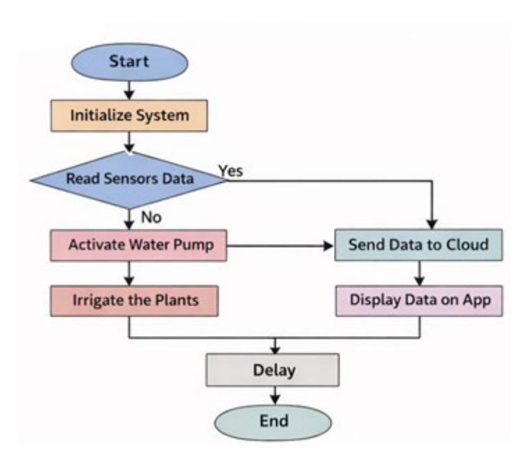
Figure 1. Operational flowchart of the proposed irrigation control system
2.2 System Block Diagram
Figure 2 illustrates the overall hardware architecture of the proposed IoT-based environmental monitoring and automated irrigation system. The NodeMCU ESP8266 functions as the central processing and communication unit, integrating sensing, control, and wireless transmission within a single platform. The microcontroller receives input signals from three primary sensors: a capacitive soil moisture sensor, a soil pH sensor, and a temperature sensor (DHT11). These sensors continuously measure soil water content, acidity level, and ambient temperature to provide comprehensive environmental information.
The collected sensor data are processed internally by the NodeMCU and transmitted via the integrated Wi-Fi module to a cloud-based monitoring platform. This wireless communication enables real-time data visualization through a smartphone application, allowing users to remotely monitor soil and environmental conditions without direct field access. Such an architecture aligns with IoT-based smart agriculture frameworks that emphasize connectivity, remote accessibility, and cloud integration.
In addition to monitoring functionality, the system incorporates an automated irrigation mechanism. The NodeMCU controls a relay module that acts as an electronic switching interface between the low-power microcontroller and the higher-power DC water pump. When the soil moisture value falls below a predefined threshold, the microcontroller sends a signal to activate the relay, turning on the water pump to irrigate the plants. Once the soil moisture reaches the desired level, the relay is deactivated, stopping the pump automatically. This closed-loop control structure enhances water-use efficiency and prevents excessive irrigation, supporting precision agriculture principles.
Overall, Figure 2 demonstrates the integration of sensing units, processing module, communication interface, and actuation system within a unified IoT framework designed for sustainable agricultural applications.
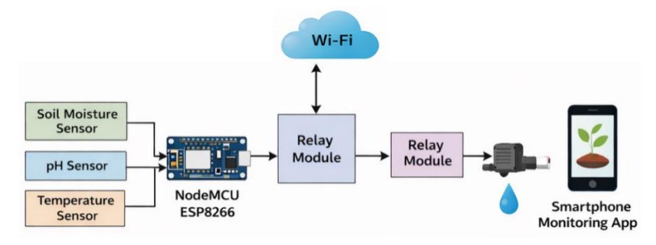
Figure 2. System block diagram of the proposed IoT-based smart irrigation system
2.3 Materials
The list of hardware components used in this study, along with their technical specifications and unit costs, is presented in Table 1.
Table 1. Technical specifications and cost of each component
| Component | Specification | Function | Cost per unit - currency |
|---|---|---|---|
| NodeMCU ESP8266 | 80 MHz MCU, WiFi 2.4 GHz, 3.3V logic | Main controller and IoT communication module | $3.00 |
| Capacitive Soil Moisture Sensor v1.2 | Analog output, operating voltage 3.3–5V, corrosion-resistant probe | Measures soil moisture level | $1.50 |
| Soil pH Sensor Module (PH4502C) | Measurement range pH 0–14, analog output, 5V supply | Measures soil acidity (pH level) | $12.00 |
| DHT11 Temperature Sensor | Temperature range 0–50°C, humidity 20–90% RH, digital output | Measures ambient temperature and humidity | $1.20 |
| 1-Channel Relay Module 5V | rigger voltage 5V, optocoupler isolation | Controls automatic irrigation pump switching | $0.80 |
| Mini DC Water Pump 5V | Operating voltage 3–6V, flow rate ±120 L/h | Acts as water actuator for irrigation | $1.30 |
| LCD 16×2 with I2C Interface | 5V supply, I2C communication (SDA/SCL) | Displays real-time monitoring data locally | $2.00 |
| LM2596 Buck Converter | Input 4–35V, adjustable output 1.25–30V, max current 3A | Steps down voltage from 12V to 5V/3.3V | $1.00 |
| 12V DC Power Adapter | Output 12V DC, current 2A–5A | Main power supply for the system | $3.50 |
| Jumper Wires | Male–Female, 20 cm length | Electrical connections between modules | $0.50 |
| Breadboard / PCB | 400 tie-points | Circuit prototyping and assembly | $1.50 |
| Resistor & Connector Kit | 220Ω–10kΩ assortment | Signal conditioning and circuit protection | $0.70 |
| Total | |||
2.4 Experimental Procedure
2.4.1. System Overview
The experimental procedure was conducted to evaluate the performance of the proposed IoT-based smart agricultural monitoring and automated irrigation system. The overall system consists of environmental sensing modules, a microcontroller-based control unit, communication interfaces, and an automatic irrigation actuator. The main objective of this experiment is to assess the system's ability to monitor soil and environmental conditions in real time and to automatically control irrigation based on predefined soil moisture thresholds.
The system integrates a NodeMCU ESP8266 microcontroller as the central processing and communication unit. Three primary sensors are employed to collect environmental data, namely a capacitive soil moisture sensor for measuring soil water content, a soil pH sensor for determining soil acidity, and a DHT11 sensor for monitoring ambient temperature and humidity. These sensors provide continuous input signals to the microcontroller, which processes the data and determines the irrigation control action.
The output subsystem consists of a relay module connected to a DC water pump that functions as the irrigation actuator. When the soil moisture level drops below a predefined threshold, the relay is activated to turn on the pump, supplying water to the plant medium. Conversely, when sufficient soil moisture is detected, the system automatically deactivates the pump to prevent excessive water usage. Additionally, a 16×2 LCD module is used to display real-time parameter values locally, while wireless communication via WiFi enables remote monitoring through a cloud-based mobile application platform. This architecture ensures continuous environmental monitoring and automated irrigation control in a closed-loop system. The overall architecture of the proposed system integrates sensing, processing, and actuation modules, as illustrated in Figure 3.
Figure 3. System block diagram of the IoT-based smart irrigation system
2.4.2. Hardware Setup and Wiring
The experimental setup began with the assembly of all hardware components according to the designed electronic wiring configuration. The NodeMCU ESP8266 was used as the main controller and connected to the sensors through appropriate analog and digital input pins. The soil moisture sensor and soil pH sensor were interfaced using analog input channels, while the DHT11 sensor was connected through a digital GPIO pin for temperature and humidity acquisition.
Figure 4. Electronic wiring diagram of the proposed system
The relay module was interfaced with the NodeMCU output pin to control the switching operation of the DC water pump. The pump received its power supply from a regulated DC source through the relay contacts, enabling safe electrical isolation between the control circuit and the power actuator. A buck converter module was used to regulate the voltage from the main power adapter to the required operating levels of 5V and 3.3V for different modules. The LCD 16×2 display module was connected via the I2C communication interface to provide local visualization of sensor readings and system status.
All wiring connections were verified to ensure stable signal transmission, proper grounding, and electrical safety before conducting the experiment. This hardware configuration establishes a reliable platform for implementing real-time monitoring and automated irrigation control. The hardware components were interconnected according to the designed wiring configuration, as depicted in Figure 4.
2.4.3. Experimental Setup
After completing the hardware assembly, the experimental setup was prepared in a controlled testing environment simulating agricultural soil conditions. The soil moisture sensor probe was inserted into the planting medium to measure real-time moisture content. The soil pH sensor electrode was placed within the soil to detect acidity variations, while the DHT11 sensor was positioned near the plant area to capture ambient environmental conditions.
The NodeMCU microcontroller was programmed using a threshold-based control algorithm. The predefined soil moisture threshold range was configured based on preliminary testing results to distinguish between dry and sufficiently moist soil conditions. When the measured soil moisture value fell below the lower threshold, the controller triggered the relay module to activate the irrigation pump. When the moisture value exceeded the upper threshold, the relay was automatically deactivated to stop water flow.
During the experiment, sensor data were continuously transmitted via WiFi to the IoT cloud platform, enabling real-time monitoring through a smartphone interface. Simultaneously, the LCD display presented the current values of soil moisture, soil pH, temperature, and pump status, providing on-site monitoring capability. This configuration allowed comprehensive observation of system performance under real-time operating conditions. The experimental setup of the proposed system deployed in the testing environment is shown in Figure 5.
Figure 5. Experimental setup of the IoT-based irrigation system
2.4.4. Experimental Flowchart
The operational procedure of the experiment follows a sequential workflow that describes the interaction between sensing, processing, decision-making, and actuation processes. Initially, the system is powered on and all sensors begin to acquire environmental data. The NodeMCU controller then reads the soil moisture, soil pH, and temperature values and processes them using the programmed threshold-based control algorithm.
Next, the system evaluates whether the measured soil moisture value is below the predefined dry threshold. If the soil condition is classified as dry, the controller activates the relay module to turn on the irrigation pump. Water is then supplied to the soil until the moisture level reaches the desired range. When sufficient moisture is detected, the controller automatically turns off the pump to prevent over-irrigation.
Throughout the process, sensor readings and actuator status are continuously displayed on the LCD module and transmitted to the cloud platform for remote monitoring. The workflow is repeated continuously, forming a closed-loop automated irrigation control system. This experimental flow ensures that irrigation decisions are made dynamically based on real-time environmental conditions, thereby improving water efficiency and supporting sustainable smart agriculture implementation. The operational sequence of the experiment is summarized in the flowchart shown in Figure 6.
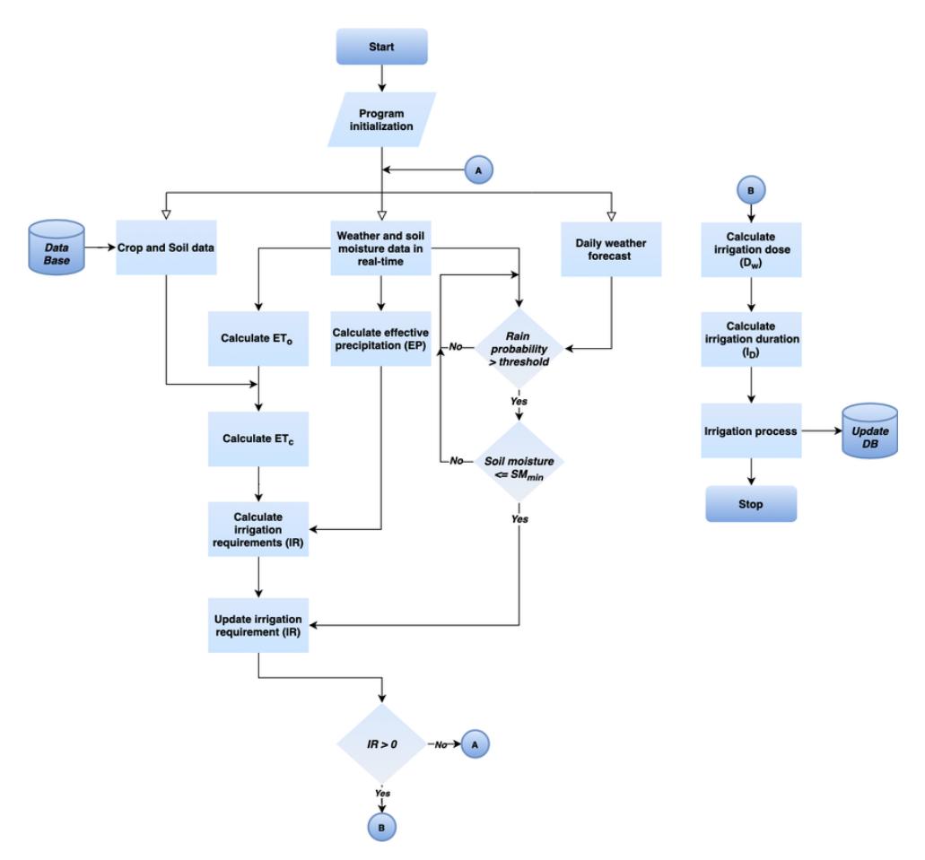
Figure 6. Experimental procedure flowchart of the automated irrigation system.
3 Results and Discussion
The system integration in this study represents the unification of hardware, software, and communication networks into a fully functional IoT-based environmental monitoring and automated irrigation system. The integration process involved interfacing the soil moisture, soil pH, and temperature sensors with the NodeMCU ESP8266 microcontroller and embedding the control algorithm developed in the Arduino IDE. The successful firmware deployment and stable communication with the cloud platform confirm that the integrated system is capable of performing real-time environmental monitoring and automated irrigation control.
This successful integration serves as the basis for further experimental validation, including sensor accuracy testing, system response analysis, and automated irrigation performance evaluation under different soil moisture conditions.
3.1 System Integration
System integration is defined as the process of constructing a unified information system from heterogeneous software, hardware, and network components. In this research, system integration refers to interfacing the IoTbased environmental monitoring and automated irrigation hardware with the control software developed using the Arduino IDE. This integration enables coordinated interaction between the sensing devices, microcontroller, and communication modules to ensure proper system functionality. Figure 7 shows the process of integrating the hardware with the software through firmware uploading using the Arduino IDE.
After completing the hardware–software integration, functional observation was conducted to verify that the developed system operates as expected. The integration was performed by connecting the device to a laptop via a USB cable to upload the embedded firmware. Prior to deployment, the program was validated to ensure that no compilation errors were present and that the selected board and communication port matched the hardware configuration. A successful firmware upload indicates that the microcontroller is ready to execute the control algorithm for real-time monitoring and automated irrigation.
Figure 7. Hardware–software integration process
3.2 IoT Monitoring Interface Using Blynk 2.0
After the hardware and software components operated properly, the next stage involved designing the Blynk application as a user interface to monitor environmental conditions and irrigation activities in the agricultural field. The interface was developed using the Blynk cloud platform and the Blynk 2.0 mobile application to enable real-time visualization and control of the IoT-based monitoring system.
The interface displays real-time readings from the soil moisture sensor, soil pH sensor, and temperature sensor. Any change in sensor values is immediately reflected on the dashboard, allowing continuous monitoring of environmental parameters. Figure 8 shows the design of the Blynk Cloud interface used for realtime monitoring of environmental data.
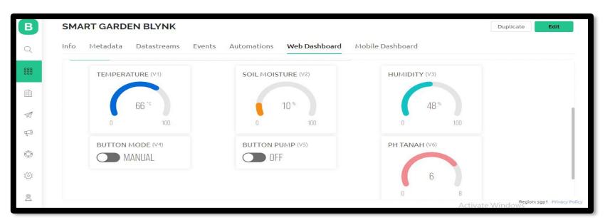
Figure 8. Blynk cloud interface design
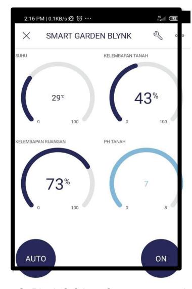
Figure 9. Blynk 2.0 interface on smartphone
In addition, two push buttons are provided on the interface: the first button is used to select the pump operating mode (manual or automatic), while the second button functions as an ON/OFF control to activate or deactivate the water pump, shown in Figure 9.
When the system operates in manual mode, the user can directly press the ON/OFF push button to start or stop the pump as required. In automatic mode, the push button must remain active, and irrigation is triggered automatically when the soil moisture value falls below or equal to 40%. Conversely, the pump stops automatically when the soil moisture level reaches or exceeds 60%, ensuring efficient and responsive irrigation
control based on real-time soil conditions. Figure 9 illustrates the Blynk 2.0 interface on the smartphone used to control and monitor the irrigation system.
3.3 Soil Moisture Sensor Testing
The soil moisture sensor testing was conducted to determine the characteristics of analog readings under different soil conditions. The experiments were performed on three main soil states: dry, moist, and wet soil. Each condition was tested multiple times to obtain the average sensor reading values. The measurement data were recorded and analyzed to evaluate the stability and sensitivity of the sensor in detecting soil moisture variations.
The results indicate that the sensor's analog output increases proportionally with the increase in soil water content. Under dry soil conditions, the readings were relatively low, while in wet soil conditions, the readings increased significantly. These results confirm that the sensor demonstrates good sensitivity in detecting realtime changes in soil moisture levels.
Measurement No. Soil moisture sensor value (%) Soil moisture value (ETP-302 reference) (%) Error value (%) Soil in normal or dry condition 1 43 40 - 0.075 2 47 40 -0.175 3 43 40 -0.075 4 41 40 -0.025 5 45 40 -0.125 Average 43.8 40 -0.095 Application of 100 mL of Water to the Soil (1) 6 82 80 -0.025 7 83 80 -0.037 8 84 80 -0.05 9 81 80 -0.012 10 82 80 -0.025 Average 82.4 80 -0.03 Application of 100 mL of Water to the Soil (2) 11 97 90 -0.078 12 94 90 -0.044 13 94 90 -0.044 14 95 90 -0.056 15 94 90 -0.044 Average 94.8 90 -0.053
Table 2. Soil moisture sensor testing results
The results presented in Table 2 show that the average measurement values of the soil moisture sensor were 43.8%, 82.4%, and 94.8% for the dry/normal condition, after the first 100 mL watering, and after the second 100 mL watering, respectively. The corresponding average error values were −0.095%, −0.03%, and −0.053% when compared with the reference instrument ETP-302. These findings indicate that the soil moisture sensor demonstrates acceptable accuracy and can reliably function as a trigger for the automated irrigation system.
The error data presented in Table 2 can be calculated using the following equation (1):
% Error = \[\frac{\text{Standard Value - Sensor Value}}{\text{Standard Value}} \times 100\] % Error = \[\frac{40-43}{40} \times 100 = \frac{-3}{40} \times 100 = -0.075\%\]
under normal or dry soil conditions is −0.095%. After the first application of 100 mL of water, the average error decreases to −0.03%, while after the second application of 100 mL of water, the average error is −0.053%. The average values were computed using the standard mean calculation formula.
The negative percentage error indicates that the standard reference value is lower than the value measured by the sensor. Conversely, the error would become positive if the standard reference value were higher than the sensor measurement. These results demonstrate that the soil moisture sensor exhibits consistent performance with acceptable deviation across different soil moisture conditions.
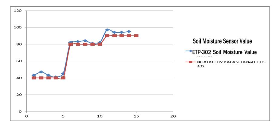
Figure 10. Comparison graph of soil moisture measurements between the soil moisture sensor and ETP-302
3.4 Temperature Sensor Testing
The developed system employs a DHT11 temperature sensor to detect ambient temperature and humidity in the surrounding environment. The DHT11 sensor is capable of measuring temperature within the range of 0– 50 °C, with a temperature measurement accuracy of approximately ±2 °C.
The sensor testing was conducted during two different time periods: daytime measurements were taken between 10:00 and 15:00 WIB, while nighttime measurements were performed between 18:00 and 23:00 WIB. During the testing process, data from the DHT11 sensor were compared with readings obtained from a reference device, the HTC-02 Hygrometer. Only ambient temperature values were considered in this evaluation, and data collection was performed ten times to obtain a representative range of measurement variations. The focus of this test was to analyze the temperature measurement performance of the DHT11 sensor under varying environmental conditions
Table 3. Temperature sensor testing
| Measurement No. | DHT11 temperature reading (°C) | HTC-02 temperature reading (°C) | DHT11 sensor error (%) |
|---|---|---|---|
| Under daytime conditions | |||
| 1 | 30 | 30.1 | 0.32 |
| 2 | 30 | 30.3 | 0.96 |
| 3 | 31 | 31.2 | 0.66 |
| 4 | 31 | 31.4 | 1.30 |
| 5 | 30 | 30.1 | 0.32 |
| Average | 30.4 | 30.7 | 0.71 |
| Under nighttime conditions | |||
| 6 | 29 | 29.1 | 0.34 |
| 7 | 29 | 29.1 | 0.35 |
| 8 | 29 | 29.1 | 0.71 |
| 9 | 28 | 28.3 | 1.04 |
| 10 | 28 | 28.2 | 0.71 |
| Average | 28.6 | 28.8 | 0.63 |
Table 3 presents the results of the DHT11 temperature sensor testing. The average temperature measurement during daytime conditions was 30.4 °C with an average measurement error of 0.71%, while during nighttime conditions the average temperature reading was 28.6 °C with an error of 0.63%.
The error data presented in Table 3 can be calculated using the following equation (2).
% Error = \[\frac{\text{Standard Value - Sensor Value}}{\text{Standard Value}} \times 100\] % Error = \[\frac{30.1 - 30}{30.1} \times 100 = \frac{0.1}{30.1} \times 100 = 32\%\]
The calculated error of 0.32% represents the discrepancy between the DHT11 sensor and the HTC-02 hygrometer. As shown in the table, the average daytime error is 0.71%, where the average ambient temperature measured by the DHT11 is 30.4°C, while the HTC-02 records 30.7°C. For nighttime measurements, the average temperature obtained from the DHT11 is 28.6°C, whereas the HTC-02 indicates 28.8°C, resulting in an average error of 0.63%. HTC-02 Temperature Reading Value
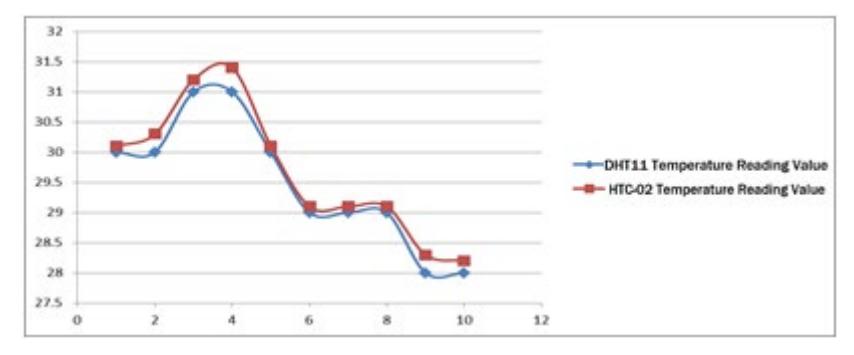
Figure 11. Comparison graph of temperature measurements between the DHT11 sensor and HTC-02 hygrometer
3.5 Soil pH Sensor Testing
The soil pH sensor in this system is used to measure the acidity to alkalinity level of the soil. The sensor has a measurement range of 3.5 to 8 pH, which covers the typical pH range required for agricultural applications. The pH sensor testing was conducted to evaluate its operational performance and measurement reliability within different soil conditions.
Measurement no. Soil pH sensor reading ETP-203 reference reading Error value (%) Compost soil 1 6.83 6.5 -0.05 2 6.62 6.5 -0.018 3 6.69 6.5 -0.029 4 6.90 7 0.014 5 6.62 6.5 -0.018 Average 6.73 6.6 -0.02 Clay soil 6 6.90 7 0.014 7 7.04 7 -0.005 8 6.80 6.5 -0.046 9 7.01 7 -0.001 10 6.90 6.5 -0.061
Table 4. Soil pH sensor testing
Table 4 presents the results of the soil pH sensor testing, which were compared with measurements obtained from the reference instrument ETP-302. The testing conducted on compost soil produced an average pH value of 6.73, indicating a near-neutral soil condition. Meanwhile, the measurements obtained from clay soil showed an average pH value of 6.93. Both soil types exhibited the same average error value of −0.2, demonstrating that the sensor provides consistent performance across different soil compositions.
Average 6.93 6.8 -0.02
The error data presented in table 4 can be calculated using the following equation (3).
\[\% \text{ Error} = \frac{\text{Standard Value - Sensor Value}}{\text{Standard Value}} \times 100\] (3)
% Error = \[\frac{6.5 - 6.83}{6.5}\] x \(100 = \frac{-0.33}{6.5}\) x \(100 = -0.05\)%
The value of −0.05% represents the overall measurement error between the soil pH sensor and the ETP-302 reference instrument. As shown in the table, the average error for compost soil is −0.02%, while clay soil also exhibits an average error of −0.02%. These results indicate a very small deviation between the sensor readings and the reference device, demonstrating good measurement accuracy across different soil types.
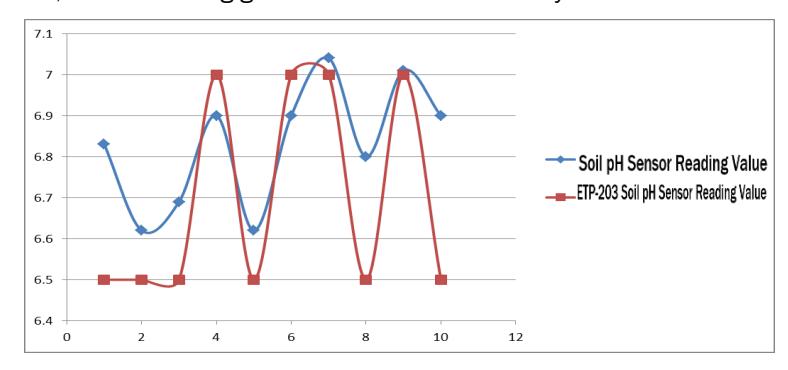
Figure 12. Comparison graph of soil pH sensor measurements with ETP-302
3.6 Overall System Performance Discussion
Based on the conducted experiments, the NodeMCU-based automatic irrigation system demonstrates satisfactory performance in detecting soil moisture levels and controlling the water pump automatically. The integration of the soil moisture sensor, NodeMCU microcontroller, relay module, and LCD display operates synchronously and stably. The main advantage of this system lies in its capability to perform real-time automatic irrigation without manual intervention, thereby improving water-use efficiency and simplifying plant maintenance. Furthermore, the LCD monitoring interface provides users with direct information regarding soil conditions and pump status.
However, several aspects require attention, such as power supply stability, potential electrical noise from the pump affecting the microcontroller, and the limitation of capacitive soil moisture sensors that are prone to corrosion over long-term usage.
Figure 13. Hardware setup of the NodeMCU-based automatic irrigation system including soil moisture sensor, relay module, LCD display, and water pump.
3.7 Research Limitations
This study has several limitations. The current study is limited to prototype-scale implementation using a single plant testing environment. Further validation is required for larger-scale farming applications involving multiple irrigation zones, longer transmission cables, voltage drop compensation, and distributed sensor networks. In addition, the current implementation has not yet been tested under real field conditions involving multiple plant nodes and wider agricultural land coverage. First, the capacitive soil moisture sensor used in this system may still experience calibration drift and reduced measurement stability over long-term use in varying soil conditions. Second, although the system already integrates IoT-based remote monitoring through the Blynk platform, further enhancement is required for large-scale cloud data management, multi-node communication, and long-term field deployment.
3.8 Implications and Future Development
The results of this study indicate that the proposed system can be implemented as a smart irrigation solution based on microcontroller technology to enhance irrigation efficiency. Future work may include integrating IoT communication modules (such as WiFi or MQTT), adding environmental sensors, and implementing intelligent control methods such as fuzzy logic or PID control to improve irrigation decision accuracy
4 Conclusion
This study presented the design, implementation, and experimental evaluation of an IoT-based environmental monitoring and automatic irrigation system using the NodeMCU ESP8266 microcontroller, which integrates soil moisture, soil pH, and temperature sensors with a relay-controlled DC water pump to enable real-time monitoring and automated irrigation based on predefined soil moisture thresholds. The experimental results demonstrate that the soil moisture sensor provides acceptable sensitivity and accuracy with average error values of −0.095%, −0.03%, and −0.053% under dry conditions and after successive 100 mL watering treatments compared to the ETP-302 reference device, while the DHT11 temperature sensor exhibits reliable performance with average errors of 0.71% during daytime and 0.63% during nighttime measurements relative to the HTC-02 hygrometer. The soil pH sensor also shows consistent accuracy across different soil types, producing average pH values of 6.73 for compost soil and 6.93 for clay soil with a small average error of −0.02%. Overall system testing confirms that the automated irrigation mechanism responds effectively to soil moisture variations by activating the pump when the soil becomes dry and stopping irrigation once sufficient moisture is achieved, thereby improving water-use efficiency and reducing manual intervention. The integration of the LCD display and Blynk-based interface further enhances usability by providing real-time visualization of environmental parameters and pump status. Despite the satisfactory performance, limitations remain, including the long-term durability of capacitive soil moisture sensors due to corrosion, potential electrical noise interference from the pump, and the need to incorporate additional environmental parameters and more advanced control algorithms. Therefore, future work should focus on employing more durable capacitive sensors, improving power and noise filtering circuits, and implementing intelligent control strategies such as fuzzy logic or PID control, as well as expanding full IoT-based cloud integration for enhanced scalability and data-driven irrigation decision-making in sustainable smart agriculture applications. Future work will focus on large-scale field deployment involving multiple plant nodes, distributed sensor modules, long-distance cable compensation, and wireless mesh communication to evaluate system scalability, robustness, and real-world irrigation efficiency under practical agricultural conditions.
Acknowledgement
This research was conducted independently without being funded by any institution.