

1. Pendahuluan
Lengan (boom) ekskavator yang mempunyai potongan berongga dengan lebar konstan dan tinggi variabel, ditumpu pada titik A dengan tumpuan sendi dan di titik C oleh piston hidraulik. pada saat ekskavator mengangkat beban, gaya-gaya yang diterima akibat beban bertitik tangkap di titik-titik E dan D, seperti ditunjukkan pada gambar 6 dan gambar 3.
Gayà-gaya yang bekerja pada lengan akibat beban dapat ditentukan dengan mekanika biasa; demikan pula besar tegangan yang terjadi pada setiap potongan, termasuk potongan berbahaya. Analisis defleksi titik-titik lengan lebih sukar dilakukan, terutama karena bentuk potongan yang tidak seragam. Metoda analisis defleksi seperti cara Castigliano, cara integrasi ganda atau cara lainnya memerlukan integrasi yang sulit dilakukan (secara analitis) karena tinggi potongan yang variabel.
Salah satu cara menentukan defleksi titik-titik lengan dengan cara yang relatif mudah adalah solusi numerik dengan metoda elemen hingga. Pada metoda elemen hingga, lengan dapat dianggap sebagai balok (beam) yang ditumpu pada dua tumpuan dengan overhang.
Formulasi matriks kekakuan untuk beam lurus yang mempunyai potongan seragam atau potongan dengan tinggi seragam dan lebar variabel, dapat ditemukan diberbagai literatur [i], [2], [3], [4], [5], [6]. Tetapi matriks
kekakuan balok yang mempunyai potongan dengan tinggi variabel belum ditemukan di literatur yang dapat terkumpul pada penulis.
Demikian juga halnya dengan matriks transformasi yang diperlukan untuk mengkonversikan matriks kekakuan lokal kedalam koordinat global sebelum matriks tersebut diglobalkan.
Makalah ini menyajikan penurunan matriks kekakuan lokal dan matriks transformasi elemen balok untuk analisis numerik dengan metode elemen hingga. Pada penurunan matriks kekakuan tersebut potongan balok disederhanakan dengan dianggap sebagai potongan pejal dengan lebar konstan dan tinggi variabel.
2. Koordinat Natural
Penurunan matriks kekakuan elemen balok dilakukan dalam koordinat natural, karena itu koordinat natural akan dijelaskan terlebih dahulu.
Mesin, Volume VI No.1&2
* 'Jurusan Mesin ITB ** PT PINDAD
Koordinat natural L<sub>1</sub> dan L<sub>2</sub> titik
P didefinisikan sebagai :
\[L_{1}(x) = \frac{x_{2} - x}{x_{2} - x_{1}} = \frac{x_{2} - x}{1}\] atau \[= \frac{1 - x}{1}\] (1)
\[L_{2}(x) = \frac{x - x_{1}}{x_{2} - x_{1}} = \frac{x - x_{1}}{1}\] \[x\] \[= \frac{x}{x} - \frac{x}{x_{1}} = \frac{x - x_{1}}{1}\] dengan :
\[L_1 + L_2 = 1 \tag{3}\]
Diferensiasi terhadap x pada Koordinat natural dilakukan sebagai berikut :
\[\frac{d}{dx} = \frac{\partial}{\partial L_1} \cdot \frac{\partial L_1}{\partial x} + \frac{\partial}{\partial L_2} \cdot \frac{\partial L_2}{\partial x}\] dengan :
\[\frac{\partial L_1}{\partial x} = -\frac{1}{-} \quad \text{dan} \quad \frac{\partial L_2}{\partial x} = \frac{1}{-}\]
Sehinga:
\[\frac{d}{dx} = \frac{1}{1} \left( \frac{\partial}{\partial L_2} - \frac{\partial}{\partial L_1} \right) \tag{4}\]
Integrasi dalam koordinat natural dilakukan dengan :
\[\int_{1}^{L} pL_{2}q \, dx = \frac{p! \, q!}{(p+q+1)!} \, 1 \tag{5}\]
p dan q adalah pangkat dalam bilangan integer.
\[p! = 1.2.3...(p-1).p\]
\[q! = 1, 2, 3, ... (q-i), q\]
3. Penurunan Matriks Fungsi Bentuk [N]
Gambar 2
Lendutan w dan perpindahan sudut \(\Theta\) untuk setiap titik elemen dengan koordinat natural (\(L_1\), \(L_2\)) dapat dituangkan dalam bentuk diskret sebagai fungsi dari lendutan dan perpindahan sudut kedua titik nodalnya berturutturut \(w_1\), \(\Theta_1\), \(w_2\) dan \(\Theta_2\) sebagai berikut:
\[w = \phi_1 w_1 + \phi_2 \theta_1 + \phi_3 w_2 + \phi_4 \theta_2\] (6)
\[\Theta = \frac{dw}{dx} = w_1 \frac{d\phi_1}{dx} + \Theta_1 \frac{d\phi_2}{dx} + w_2 \frac{d\phi_3}{dx} + \Theta_2 \frac{d\phi_4}{dx}\] \[\cdots \cdots (7)\] dengan
\[\phi_1 = a_1L_1^3 + b_1L_1^2L_2 + c_1L_1L_2^2 + d_1L_3^3\],
\(\vdots = 1, 2, 3, 4, ...\) (8)
Untuk mengevaluasi \(a_i\), \(b_i\), \(c_i\), \(d_i\) i=1,2,3,4 dipergunakan kondisi batas berikut :
Untuk x=0 (atau x=x): \[\begin{bmatrix} w = w \\ 1 \\ 0 = \theta_1 \end{bmatrix}\]
Untuk x=1 (atau x=x2): \[\begin{bmatrix} w = w \\ e \end{bmatrix}\] and \(\theta = \theta_2\) .... (10)
Kondisi Batas (9) menghasilkan kondisi pada \(\phi_1\) dan \(\frac{d\phi_1}{dx}\), i = 1,2,3,4 sebagai berikut :
Untuk x=0 : \[\phi_1\]=1 dan \(\phi_2\)=\(\phi_3\)=\(\phi_4\)=0 ....(11)
\[\bullet\Theta_1 = \frac{d\phi_2}{dx} = 1 \ dan \frac{d\phi_1}{dx} = \frac{d\phi_3}{dx} = \frac{d\phi_4}{dx} = 0\]
. . . . (12)
Untuk \(\kappa=1\) : \(\phi_3=1\) dan \(\phi_1=\phi_2=\phi_4=0\)
... (13)
\[\Theta_2 = \frac{d\phi_4}{dx} = 1 \operatorname{dan} \frac{d\phi_1}{dx} = \frac{d\phi_2}{dx} = \frac{d\phi_3}{dx} = 0\]
.... (14)
Menentukan \(a_1\), \(b_1\), \(c_1\) dan \(d_1\) dari persamaan (11), (13) dan (14):
\[\phi_1 = a_1L_1^3 + b_1L_1^2L_2 + c_1L_1L_2^2 + d_1L_2^3\]
....(15)
dan persamaan \(\frac{d\phi}{dx}\) berikut :
\[\frac{d\phi}{dx} = -\frac{1}{1} \frac{d\phi}{dL_1} + \frac{1}{1} \frac{d\phi}{dL_2}\]
u t an at aı an tt:
6)
7)
\[\frac{ds_1}{dx} = -\frac{1}{1} (3a_1L_1^2 + 2b_1L_1L_2 + cL_2^2) + \frac{1}{1} (b_1L_1^2 + 2c_1L_1L_2 + 3d_1L_2^3)\] dengan kondisi :
(atau x=x1) \[L_2 = 0\] : \[\begin{bmatrix} \phi & = 1 \\ \frac{d\phi}{dx} & = 0 \end{bmatrix}\]
.... (17) & (18)
(atau x=x2) \[L_{2} = 1\] \[L_{2} = 1\] \[(19) & (20)\]
Dari Persamaan (17) diperoleh harga \(a_i\) sebagai berikut :
\[\phi_1 = 1 = a_1(1)^3 + b_1(1)^2(0) + c_1(1)(0)^2 + d_1(0)^3\]
\(a_1 = 1\) .....(21)
Mesin, Volume VI No.1&2
Sedangkan dari persamaan (18) diperoleh harga b, sebagai berikut :
\[\frac{dx}{dx} = -\frac{i}{1} \left[ 3(1)(1)^2 + 0 + 0 \right] + \frac{i}{1} \left[ b_1(1)^2 + 0 + 0 \right]\]
\[b_1 = 3\] .... (22)
Dari pers (19) diperoleh harga d<sub>1</sub> sebagai berikut :
\[\phi_1\] = 0 = (1) (0) 3+3(0) 2(1) + \(c_1\) (0) (1) 2+\(d_1\) (1) 3
\[d_1 = 0\] .... (23
sedangkan dari persamaan (20) diperoleh harga \(c_1\) sebagai berikut :
\[\frac{d\phi}{dx}\Big|_{x=1} = 0 = \frac{1}{1} \left[ 3(1)(0)^{2} + 2(3)(0)(1) + c_{1}(1)^{2} \right]\]
\[+\frac{1}{1}\left[3(0)^{2}+2c_{1}(0)(1)+3(0)(1)\right]\]
\[c_1 = 0 \qquad (25)\]
Sehingga diperoleh:
\[ø_1 = L_1^3 + 3L_1^2L_2\] yang dapat dituliskan sebagai
\[\phi_1 = L_1^3 + 3L_1^2(1-L_1) = L_1^2(3-2L_1)\] (26)
Dengan cara analog, diperoleh :
\[a_2 = 0\] \(b_2 = 1\) \(c_2 = d_2 = 0\)
sehingga :
\[\phi_2 = L_1^2 L_2 1\] (27)
dan dengan cara yang analog pula diperoleh:
\[p^3 = L_2^2(3-L_2^2)\] (28)
dan
\[\phi_{4} = -L_{1}L_{2}^{2}1\] (29)
Akhirnya :
\[w = L_1^2(3-2L_1)w_1 + L_1^2L_21\theta_1 + L_2^2(3-2L_2)w_2 - L_1L_2^21\] (30)
atau dapat dituliskan sebagai :
\[w = [N] \{0\}\] dengan
\[[N] = \begin{bmatrix} L_1^2(3 - 2L_1), & L_1^2L_1, \\ L_2^2(3 - 2L_2), & -L_1L_2I_1 \end{bmatrix}\]
. . . . . (32)
4. <u>Penurunan Matriks Regangan-</u> <u>Perpindahan [B]</u>
Matriks regangan - perpindahan [B] untuk elemen balok dapat dihitung dari rumus berikut [6]
\[[B] = \frac{d^2}{dx^2} [N] \tag{33}\]
Dari rumus pers. (33) di atas, dapat diturunkan semua elemen (B) sebagai berikut:
\[\frac{d\phi_{1}}{dx} = \frac{d}{dx} \left[ L_{1}^{2} (3 - 2L_{1}) \right]\]
\[= -\frac{1}{1} \frac{\partial}{\partial L_1} \left[ L_1^2 \left( 3 - 2L_1 \right) \right] +\]
\[= \frac{1}{1} \frac{\partial}{\partial L_2} \left[ L_1^2 (3 - 2L_1) \right]\]
\[=-\frac{1}{1}(6L_{i}-6L_{i}^{2})+\frac{1}{1}(0)\]
\[\frac{d^{2} \phi_{i}}{dx^{2}} = -\frac{i}{1} \frac{\partial}{\partial L_{i}} \left[ -\frac{i}{1} (6L_{i} - 6L_{i}^{2}) \right] +\]
\[\frac{1}{1} \frac{\partial}{\partial L_2} \left[ -\frac{1}{1} (6L_1 - 6 L_1^2) \right]\]
\[\frac{d^2\phi_1}{dx^2} = \frac{6}{1^2} (1 - 2L_1) \tag{34}\]
Dengan cara analog diperoleh :
\[\frac{d^2 \phi_2}{dx^2} = \frac{1}{1} (2 L_2 - 4 L_1)\] (35)
\[\frac{d^2 \phi_3}{dx^2} = \frac{6}{1^2} (1 - 2 L_2)\] (36)
\[\frac{d \phi_{4}}{dx^{2}} = \frac{1}{1} (4 L_{2} - 2 L_{1})\] (37)
sehingga:
\[(B) = \frac{1}{12} \left[ (6 - 12L_{1}), 1(2L_{2} - 4L_{1}), (38) \right]\] \[(6 - 12L_{2}), 1(4L_{2} - 2L_{1})\]
5. <u>Matriks Kekakuan Elemen Balok Dengan</u> <u>Tinggi Variabel [K]</u>
Matriks kekakuan elemen balok diturunkan dari rumus [2] :
\[[K] = \int_{1}^{\infty} \{B\}^{T}[D][B] dx\] (39)
dengan
sehingga:
\[[K] = \int_{1}^{\infty} EI [B]^{T}[B] dx \qquad (4i)\]
\[[B]^{T}[B] = \frac{1}{1^{4}} \begin{bmatrix} A & B & D & G \\ & C & E & H \\ & & F & I \\ & & & J \end{bmatrix} (42)\] dengan 🗅
\[A = (6 - 12 L_1)^2\] (43)
\[B = 1 (6 - 12L_1)(2L_2 - 4L_1)\] (44)
\[C = 1^2 (2L_2 - 4L_1)^2\] (45)
34)
35)
36)
37)
38)
an lok
39)
40)
1)
(42)
(43)
(44)
18,2
\[D = (6 - 12 L_1) (6 - 12 L_2) (46)\]
\[E = 1 (2L_2 - 4L_1) (6 - 12L_2) (47)\]
\[F = (6 - 12 L_1)^2 (48)\]
\[G = 1 (6 - 12 L_1) (4L_2 - 2L_1)\] (49)
\[H = 1^{2}(2L_{2} - 4L_{1})(4L_{2} - 2L_{1})\] (50)
\[I = 1 (6 - 12L_2)(4L_2 - 2L_1)\] (51)
\[J = 1^{2} (4L_{2} - 2L_{1})^{2}\] (52)
Elemen dengan tinggi variabel dapat digambarkan sebagai berikut:
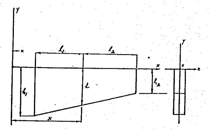
Gambar 3 Elemen balok Lentur dengan tinggi variabel
Dari gambar di atas dapat diturunkan
\[h = h_1 L_1 + h_2 L_2\] (53)
Substitusi persamaan (53) ke persamaan (54) akan diperoleh :
\[[K] = \frac{Eb}{121^{4}} \int_{1}^{1} h^{3} \begin{bmatrix} A & B & D & G \\ C & E & H \\ & & F & I \\ & & & J \end{bmatrix} dx \quad (54)\]
\[[K] = \frac{Eb}{121^{4}} \int_{1}^{1} (h_{1}L_{1} + h_{2}L_{2})^{3} \begin{bmatrix} A & B & D & G \\ & C & E & H \\ & & F & I \end{bmatrix} dK\]
Mesin, Volume VI No.1&2
\[[K] = \frac{ED}{12} \int_{1}^{1} (h_1^3 L_1^3 + 3h_1^2 L_1^2 h_2 L_2^2 + 3h_1 L_1^2 L_2^2 + h_2^3 L_2^3)\] \[= \frac{ED}{12} \int_{1}^{1} (h_1^3 L_1^3 + 3h_1^2 L_1^2 h_2 L_2^2 + h_2^3 L_2^3)\] \[= \frac{A}{12} \int_{1}^{1} (h_1^3 L_1^3 + 3h_1^2 L_1^2 h_2 L_2^3)\] \[= \frac{A}{12} \int_{1}^{1} (h_1^3 L_1^3 + 3h_1^2 L_1^3 h_2 L_2^3)\] \[= \frac{A}{12} \int_{1}^{1} (h_1^3 L_1^3 + 3h_1^2 L_1^3 h_2 L_2^3)\] \[= \frac{A}{12} \int_{1}^{1} (h_1^3 L_1^3 + 3h_1^2 L_1^3 h_2 L_2^3)\] \[= \frac{A}{12} \int_{1}^{1} (h_1^3 L_1^3 + 3h_1^3 L_1^3 h_2 L_2^3)\] \[= \frac{A}{12} \int_{1}^{1} (h_1^3 L_1^3 + 3h_1^3 L_2^3 L_2^3)\] \[= \frac{A}{12} \int_{1}^{1} (h_1^3 L_1^3 + 3h_1^3 L_2^3 L_2^3)\]
\[\{k\} = \frac{EI}{1^4} \int_1^1 L_1^3 \begin{bmatrix} A & B & D & G \\ & C & E & H \\ & & F & I \\ & & & J \end{bmatrix} dx +\]
\[\frac{3EI}{1^{\frac{1}{4}}} \stackrel{h}{h_{1}} \int_{1}^{1} L_{2}^{2} L_{2} \begin{bmatrix} A & B & D & G \\ & C & E & H \\ & & F & 1 \\ & & & & \end{bmatrix} dx +\]
\[\frac{3EI}{1^4} \stackrel{h}{\underset{2}{\stackrel{}{\stackrel{}}{\stackrel{}}}} \int_{1}^{L_1 L_2} \left[ \begin{array}{cccc} A & B & D & G \\ C & E & H \\ & & F & J \end{array} \right] dx +\]
\[\text{[rumus tidak dapat ditampilkan dengan baik — lihat PDF asli]}\]
Integrasi elemen [k] dilakukan dengan cara yang ditunjukkan oleh pers. (5). Berikut ini akan ditunjukkan cara integrasi untuk satu elemen saja, yaitu elemen pertama matriks pertama:
\[\frac{EI}{1^{\frac{4}{4}}} \int_{0}^{1} L_{1}^{3} A dx = \frac{EI}{1^{\frac{4}{4}}} \int_{0}^{1} L_{1}^{3} (6 - i2L_{1})^{2} dx\] \[= \frac{EI}{1^{\frac{4}{4}}} \int_{0}^{1} L_{1}^{3} (36 - i44 L_{1})^{2} dx\] \[+ i44 L_{1}^{2} dx\]
\[= \frac{EI_{1}}{1^{4}} \left[ 36 \int_{1}^{1} L_{1}^{3} dx - \frac{1}{1^{4}} L_{1}^{1} dx + \frac{1}{1^{4}} L_{1}^{1} dx \right]\] \[= \frac{EI_{1}}{1^{4}} \left[ (36) \frac{3!}{(3+1)!} - (144) \frac{4!}{(4+1)!} + (144) \frac{5!}{(5+1)!} \right] 1\] \[= (4.2) \frac{EI_{1}}{1^{3}}\]
Setelah dilakukan 40 kali integrasi seperti di atas diperoleh :
\[[K] = \frac{EI}{1^3} \begin{bmatrix} 4, 2 & 31 & -4, 2 & 1, 21 \\ & 2, 21^2 & -31 & 0, 81 \\ & & 4, 2 & -1, 21 \\ & & & 0, 41^2 \end{bmatrix} +\]
\[\text{[rumus tidak dapat ditampilkan dengan baik — lihat PDF asli]}\]
\[\text{[rumus tidak dapat ditampilkan dengan baik — lihat PDF asli]}\]
\[\text{[rumus tidak dapat ditampilkan dengan baik — lihat PDF asli]}\]
Persamaan (56) adalah matriks kekakuan [k] untuk balok lentur yang mempunyai lebar b konstan, tinggi h yang variabel
Dapat dicatat bahwa jika ke dalam [k] tersebut diatas dimasukkan \(\frac{h_1}{h_2}\frac{h_2}{h_1}=i\) akan diperoleh harga
\[[K] = \frac{EI}{3} \begin{bmatrix} 12 & 61 & -12 & 61 \\ & 41^2 & -61 & 21^2 \\ & & 12 & -61 \\ & & 41^2 \end{bmatrix}\]
..... (56)
ar
yaitu matriks kekakuan lokal untuk potongan seragam.
6. Matriks Transformasi
Sebelum matriks kekakuan elemen yang sumbunya tidak sejajar sumbu x koordinat global diglobalkan, maka matriks tersebut terlebih dahulu ditransformasikan terlebih dahulu.
Terlebih dahulu, perhatikan balok yang menerima beban dengan arah miring seperti tertera dalam gambar berikut :
Gambar 4
Hanya komponen vertikai Pcosa saja yang mengakibatkan defleksi (perpindahan vertikal), sedangkan komponen horisontalnya Psina dianggap tidak menimbulkan perpindahan horizontal. Karena itu pada elemen dengan orientasi miring terhadap sumbu global x yang menerima beban vertikal, hanya komponen tegak lurus terhadap elemennya saja yng berkontribusi pada hubungan gaya-defleksi:
\[\begin{bmatrix} \mathbf{K} \\ \mathbf{I} \\ \mathbf{\Theta} \\ \mathbf{I} \\ \mathbf{W} \\ \mathbf{Z} \\ \mathbf{\Theta} \\ \mathbf{Z} \end{bmatrix} = \begin{bmatrix} \mathbf{P} \\ \mathbf{I} \\ \mathbf{M} \\ \mathbf{I} \\ \mathbf{P} \\ \mathbf{Z} \\ \mathbf{H} \\ \mathbf{Z} \end{bmatrix}\](58)
P = komponen P tegaklurus elemen, beban yang menyebabkan lenturan.
\[P_1 = P_1 \cos \alpha\]
(56)
riks yang yang alam
= 1
tuk
men x aka
ulu
lok
ing
osα
ksi kan gap han nen mbu al, dap
3.2
Defleksi titik nodal i elemen miring akibat P adalah w Defleksi w i tersebut mempunyai komponen w dalam arah koordinat global.
Gambar berikut menunjukkan elemen balok yang membentuk sudut \(\alpha\) dengan sumbu \(\kappa\).
Gambar 5
Hubungan antara beban pada sisitem lokal dan sistem global,
\[P = P \cos \alpha\] \[1 = 1\] \[M = M\] \[1 = 1\] \[P = P \cos \alpha\] \[2 = 2\] \[M_2 = M_2\] (59)
Hubungan antara perpindahan pada sistem lokal dan sistem global,
\[\begin{array}{lll} \mathbf{W}_{1} &=& \frac{\mathbf{W}_{1}}{\cos \alpha} \\ \Theta_{1} &=& \frac{\overline{\Theta}_{1}}{\mathbf{W}_{2}} \\ \mathbf{W}_{2} &=& \frac{\overline{\mathbf{W}}_{2}}{\cos \alpha} \\ \Theta_{2} &=& \overline{\Theta}_{2} \end{array}\] (60)
Mesin, Volume VI No.1&2
Substitusi persamaan (59) dan (60) ke dalam persamaan (58).
\[[K] \begin{bmatrix} w_{1}/\cos\alpha \\ u_{2}\\ \overline{\Theta} \\ w_{2} \end{bmatrix} = \begin{bmatrix} P_{1}\cos\alpha \\ M \\ P_{2}\cos\alpha \\ \overline{M} \\ -2 \\ \overline{M} \\ 2 \end{bmatrix}\](61)
. . . . . . (62)
\[\begin{bmatrix} \overline{w}_{1}/\cos\alpha \\ \overline{\theta}_{1} \\ \overline{w}_{2}/\cos\alpha \\ \overline{\theta}_{2} \end{bmatrix} = \begin{bmatrix} \cos\alpha & 0 & 0 & 0 \\ 0 & 1 & 0 & 0 \\ 0 & 0 & \cos\alpha & 0 \\ 0 & 0 & 0 & 1 \end{bmatrix} \begin{bmatrix} \overline{p}_{1} \\ \overline{m}_{1} \\ \overline{p}_{2} \\ \overline{m}_{2} \end{bmatrix}\]
Persamaan (62) dapat ditulis:
\[\begin{bmatrix} \frac{1}{\cos\alpha} & 0 & 0 & 0 \\ 0 & 1 & 0 & 0 \\ 0 & 0 & \frac{1}{\cos\alpha} & 0 \\ 0 & 0 & 0 & 1 \end{bmatrix} \begin{bmatrix} \overline{w} \\ 1 \\ \overline{\Theta} \\ 1 \\ \overline{w} \\ 2 \\ \overline{\Theta} \\ 2 \end{bmatrix} =\]
\[\begin{bmatrix} \cos \alpha & 0 & 0 & 0 \\ 0 & i & 0 & 0 \\ 0 & 0 & \cos \alpha & 0 \\ 0 & 0 & 0 & i \end{bmatrix} \begin{bmatrix} \frac{1}{P} \\ -1 \\ M \\ -1 \\ P \\ -2 \\ M_2 \end{bmatrix}\] (63)
Semua suku dikalikan dengan matriks
| - i cosα | 0 | 0 | 0 | 1 cosα | 0 | Ó | 0 | w̃ 1 | ||
|---|---|---|---|---|---|---|---|---|---|---|
| 0 | 1 | 0 | 0 | [K] | 0 | 1 | 0 | 0 | ē | |
| ,0, | 0 | \[\frac{i}{\cos\alpha}\] | 0 | 0 | 0 | \[\frac{i}{\cos \alpha}\] | 0 | w 2 | ||
| 0 | 0 | 0 | 1 | 0 | 0 | o | 1 | ē2. |
\[[K] = \begin{bmatrix} \frac{1}{\cos \alpha} & 0 & 0 & 0 \\ 0 & i & 0 & 0 \\ 0 & 0 & \frac{1}{\cos \alpha} & 0 \\ 0 & 0 & 0 & i \end{bmatrix} \begin{bmatrix} \frac{1}{\cos \alpha} & 0 & 0 & 0 \\ 0 & i & 0 & 0 \\ 0 & 0 & \frac{1}{\cos \alpha} & 0 \\ 0 & 0 & 0 & i \end{bmatrix}\]
\[= \begin{bmatrix} \mathbf{I} \end{bmatrix} \begin{bmatrix} \mathbf{\bar{P}} \\ \mathbf{\bar{M}} \\ \mathbf{\bar{P}} \\ \mathbf{\bar{P}} \\ \mathbf{\bar{M}} \\ \mathbf{\bar{M}} \end{bmatrix}\] \[(64)\] dengan \([\bar{K}]\) adalah matriks kekauan lokal yang sudah ditransformasi.
..... (65)
Persamaan (64) adalah persamaan Kesetimbangan matriks kekakuan lokal yang sudah ditransformasi, dan dapat dituliskan sebagai berikut :
7. <u>Penerapan Pada Lengan (Boom)</u> <u>Ekskavator</u>
Gambar menunjukkan posisi ekskavator pada saat operasi pengangkatan dan pada posisi ini dianggap pembebanan kritis terhadap balok pengangkat.
Gambar 6. Salah satu posisi pada saat pengangkatan
Untuk menhitung beban pada balok pengangkat, lihat digaram benda bebas
sitem lengan balok pengangkat dengan ember, pada gambar berikut :
Mesin, Volume VI No.1&2
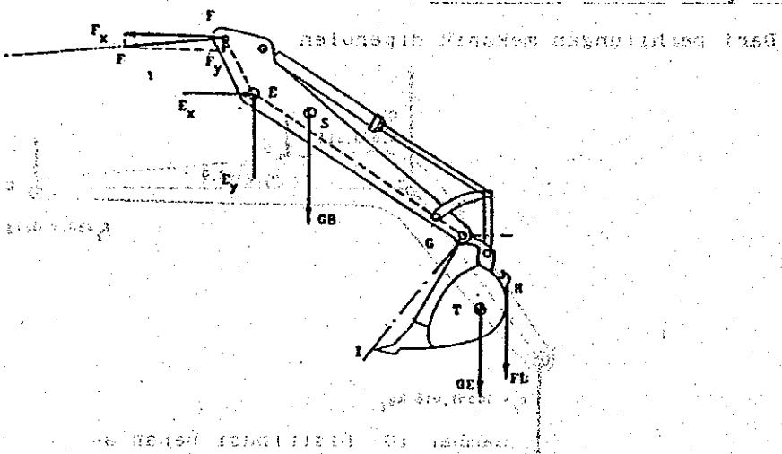
Gambar 7. Diagram benda bebas sistem lengan dan ember
Gambar 8. Diagram benda bebas untuk sistem balok pengangkat
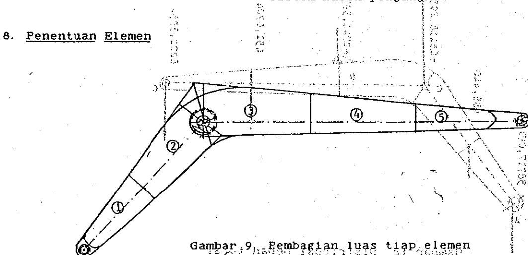
Mestin / Volume VI No. 182
65)
Kal
sisi atan anan an 8.2 bε 33
9. Beban pada lengan ekskavator
Dari perhitungan mekanik diperoleh
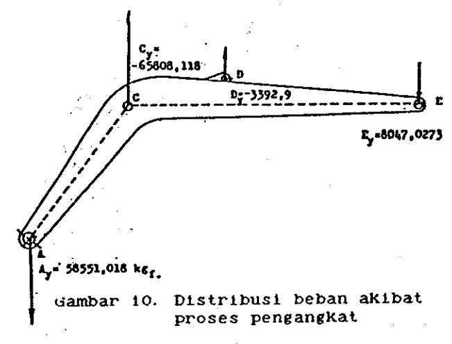
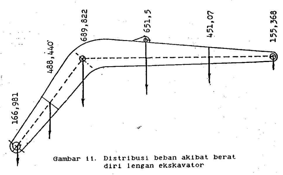
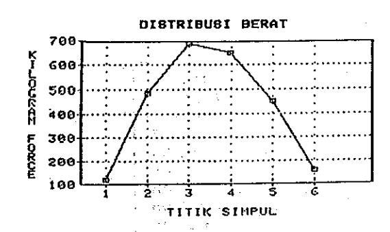
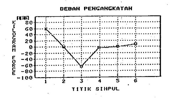
Distribusi berat lengan pengangkat
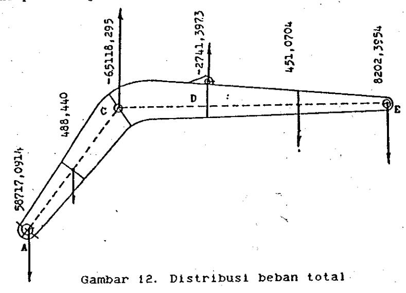
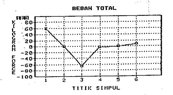
Beban total pada lengan ekskavator
DATA MASUKAN
NE : Jumlah elemen = 5
| PANJANG (METER) |
|---|
| 1. 1200 |
| 1. 1200 |
| 1.3443 |
| 1. 3443 |
| 1.3443 |
| Nomor Elemen | SUDUT (RADIAN) |
|---|---|
| . 1 | 0. 872664639000 |
| 2 | 0.872664639000 |
| - 3 | 0. 00000000000 |
| 4 | 0. 00000000000 |
| 5 | 0. 000000000000 |
| NOMOR | TINGGI | ||
|---|---|---|---|
| SIMPUL | (METER) | ||
| 1 | 0.158135222000 | ||
| 2 | 0.270191006000 | ||
| 3 | 0.342981106000 | ||
| 4 | 0.291324265000 | ||
| 5 | 0.133370471000 | ||
| NOMOR DERAJAT KEBEBASAN | BEBAN (KILOGRAM-FORCE) | ||
|---|---|---|---|
| 1 | 0. 00000000 | ||
| 2 | 0.00000000 | ||
| 3 | 488. 44000000 | ||
| 4 | 0.00000000 | ||
| 5 | 0.0000000 | ||
| 6 | 0.0000000 | ||
| 7 | -2741. 39730000 | ||
| 8 | 0. 00000000 | ||
| 9 | 451.07040000 | ||
| 10 | 0. 00000000 | ||
| 11 | 8202, 39540000 | ||
| 12 | 0. 00000000 | ||
KETERANGAN:
L(N): Panjang elemen balok lentur A(N): Sudut balok lentur terhadap
sumbu x
H(N): Tinggi balok lentur
B(N): Vektor beban pada derajat kebebasan ke n
KELUARAN PROGRAM
| the state of the state of the state of the state of the state of the state of the state of the state of the state of the state of the state of the state of the state of the state of the state of the state of the state of the state of the state of the state of the state of the state of the state of the state of the state of the state of the state of the state of the state of the state of the state of the state of the state of the state of the state of the state of the state of the state of the state of the state of the state of the state of the state of the state of the state of the state of the state of the state of the state of the state of the state of the state of the state of the state of the state of the state of the state of the state of the state of the state of the state of the state of the state of the state of the state of the state of the state of the state of the state of the state of the state of the state of the state of the state of the state of the state of the state of the state of the state of the state of the state of the state of the state of the state of the state of the state of the state of the state of the state of the state of the state of the state of the state of the state of the state of the state of the state of the state of the state of the state of the state of the state of the state of the state of the state of the state of the state of the state of the state of the state of the state of the state of the state of the state of the state of the state of the state of the state of the state of the state of the state of the state of the state of the state of the state of the state of the state of the state of the state of the state of the state of the state of the state of the state of the state of the state of the state of the state of the state of the state of the state of the state of the state of the state of the state of the state of the state of the state of the state of the state of the state of the state of the state of the state of the state of the state of the state of the s | ||
|---|---|---|
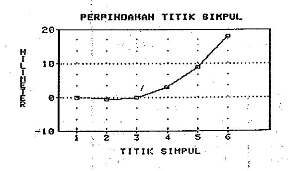
| NOMOR SIMPUL | PERPINDAHAN LATERAL (M) | PERPINDAHAN SUDUT (RAD) |
| 1 | 000000.00000E+00 | -12623. 02460E-07 |
| 2 | -21062.45450E-08 | -22548.31160E-09 |
| 3 | 000000.00000E+00 | 143187. 52500E-08 |
| 4 | 313638.20500E-08 | 329299. 82100E-08 |
| 5 | 904676, 93800E-08 | 557323. 74400E-08 |
| 6 | 180512.77800E-07 | 757610.05600E-08 |
| i . |
| ELEMEN NO: 1 | SIMPUL NO: 1 | SIMPUL NO: 2 |
|---|---|---|
| GAYA LINTANG | -40591.21340E-01 | 405912.13400E-02 |
| MOMEN LENTUR | -68997.98760E-01 | 397906.23100E-02 |
| TEG. NORMAL | -45668.05660E+02 | 263364.26500E+01 |
| ELEMEN NO: 2 | SIMPUL NO: /2 | SIMPUL NO: 3 |
|---|---|---|
| GAYA LINTANG | 131924. 07500+00 | -13192.40750E+01 |
| MOMEN LENTUR | 199824. 49000E-01 | 749891.66600E-01 |
| TEG. NORMAL | 453043. 87800E+01 | 170016.11200E+02 |
| ELEMEN NO: 3 | SIMPUL NO: 3 | SIMPUL NO: 4 |
|---|---|---|
| GAYA LINTANG | -59120. 68550E-01 | 591206. 85500E-02 |
| MOMEN LENTUR | -30634. 87290E+00 | 226756. 93600E-01 |
| TEG. NORMAL | -43103. 15100E+02 | 319046. 15600E+01 |
AND THE ALL MENTS
| ELEMEN NO: 4 | SIMPUL NO: 4 | SIMPUL NO: 5 |
|---|---|---|
| GAYA LINTANG | -86534.65790E-01 | 865346. 57900E-02 |
| MOMEN LENTUR | -22675.69350E+00 | 110317. 09500E-01 |
| TEG. NORMAL | -44222.22510E+02 | 215140. 82400E+01 |
| ELEMEN NO: 5 | SIMPUL NO: 5 | SIMPUL NO: 6 |
|---|---|---|
| GAYA LINTANG | -82023.95430E-01 | 820239.54300E-02 |
| MOMEN LENTUR | -11031.70950E+00 | 000000.00000E+00 |
| TEG. NORMAL | -39148.19060E+02 | 000000.00000E+00 |
KETERANGAN :
P(1), P(2) : GAYA LINTANG M(1), M(2) : MOMEN LENTUR SG(1), SG(2) : TEGANGAN NORMAL
Pustaka
- i. Zienkiewicz, O.C., The Finite Element Method in Engineering Science, McGraw-Hill Publishing Company
- Limited, 1971. 2. Desai, C.S. & Abel, J.F., Introduction to The Finite Element Method, Van Nostrand Reinhold
- Gompany, 1972. 3. Gallagher, R. H., Finite Element Analysis Fundamental, Prentice-Hall Inc., 1975.
- Finite Element Method for Engineers, 2nd ed., John Wiley & Sons, 1982.
- 6. Cook, R.D., Concept and Applications
- 4. Weaver, W. Jr. & Gere, J. M., Matrix of Finite Element Analysis, 2nd. ed., Analysis of Framed Structures, Second John Wiley & Sons, 1981. Edition, D. Van Nostrand Company, 7. Waskitho, Heri, Formulasi Elemen Hingga Untuk Balok Lentur Dan Penerapannya Terhadap Balok Penerapannya Terhadap Balok Penerapannya Terhadap Balok Penerapannya Terhadap Balok Penerapannya Terhadap Balok Penerapannya Terhadap Balok Penerapannya Terhadap Balok Penerapannya Terhadap Balok Penerapannya Terhadap Balok Penerapannya Terhadap Balok Penerapannya Terhadap Balok Penerapannya Terhadap Balok Penerapannya Terhadap Balok Penerapannya Terhadap Balok Penerapannya Terhadap Balok Penerapannya Terhadap Balok Penerapannya Terhadap Balok Penerapannya Terhadap Balok Penerapannya Terhadap Balok Penerapannya Terhadap Balok Penerapannya Terhadap Balok Penerapannya Terhadap Balok Penerapannya Terhadap Balok Penerapannya Terhadap Balok Penerapannya Terhadap Balok Penerapannya Terhadap Balok Penerapannya Terhadap Balok Penerapannya Terhadap Balok Penerapannya Terhadap Balok Penerapannya Terhadap Balok Penerapannya Terhadap Balok Penerapannya Terhadap Balok Penerapannya Terhadap Balok Penerapannya Terhadap Balok Penerapannya Terhadap Balok Penerapannya Terhadap Balok Penerapannya Terhadap Balok Penerapannya Terhadap Balok Penerapannya Terhadap Balok Penerapannya Terhadap Balok Penerapannya Terhadap Balok Penerapannya Terhadap Balok Penerapannya Terhadap Balok Penerapannya Terhadap Balok Penerapannya Terhadap Balok Penerapannya Terhadap Balok Penerapannya Terhadap Balok Penerapannya Terhadap Balok Penerapannya Terhadap Balok Penerapannya Terhadap Balok Penerapannya Terhadap Balok Penerapannya Terhadap Balok Penerapannya Balok Penerapannya Balok Penerapannya Balok Penerapannya Balok Penerapannya Balok Penerapannya Balok Penerapannya Balok Penerapannya Balok Penerapannya Balok Penerapannya Balok Penerapannya Balok Penerapannya Balok Penerapannya Balok Penerapannya Balok Penerapannya Balok Penerapannya Balok Penerapannya Balok Penerapannya Balok Penerap Pengangkat Ekskavator, Jurusan Teknik Mesin Institut Teknologi Bandung, 1984.
Control of the second of the second of the second of the second of the second of the second of the second of the second of the second of the second of the second of the second of the second of the second of the second of the second of the second of the second of the second of the second of the second of the second of the second of the second of the second of the second of the second of the second of the second of the second of the second of the second of the second of the second of the second of the second of the second of the second of the second of the second of the second of the second of the second of the second of the second of the second of the second of the second of the second of the second of the second of the second of the second of the second of the second of the second of the second of the second of the second of the second of the second of the second of the second of the second of the second of the second of the second of the second of the second of the second of the second of the second of the second of the second of the second of the second of the second of the second of the second of the second of the second of the second of the second of the second of the second of the second of the second of the second of the second of the second of the second of the second of the second of the second of the second of the second of the second of the second of the second of the second of the second of the second of the second of the second of the second of the second of the second of the second of the second of the second of the second of the second of the second of the second of the second of the second of the second of the second of the second of the second of the second of the second of the second of the second of the second of the second of the second of the second of the second of the second of the second of the second of the second of the second of the second of the second of the second of the second of the second of the second of the second of the second of the second of the second of the second of the s
451...p3