

ENVIRONMENTAL IMPACTS
Water is such an effective and economical heat transfer fluid that almost all large air conditioning plant based on vapour compression uses packaged water chillers. Table 1 list the two most popular chiller refrigerants and potential replacements in order of direct environmental impact. The Montreal Protocol to protect the stratospheric ozone layer requires all signatories to cease manufacture or import of R11 the most popular for chillers by 2005. The second most popular R22 and the recently introduced R123 are to be severely reduced in 2005 and phased out before 2030 by signatories with large emissions per head and ten years later for others.
Table 1 also includes the boiling point at standard atmospheric pressure. Refrigerants with similar boiling points and molecular mass can be substituted for each other in chillers. Three potential replacements have been included for R11 or R123 and three for R22.
A brief summary of chiller and compressor, designs and developments is followed by the comparison of thermodynamic and transport properties for the above refrigerants in Tables 2 and 3. These allow identification of practical replacement options.
CHILLER DESIGNS
Water chillers use the reversed Rankine cycle or simple modifications of it and so have the four basic compo-
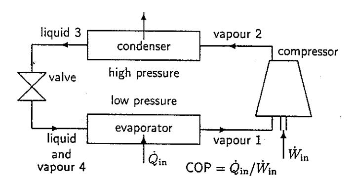
Figure 1: Schematic of vapour compression refrigeration cycle.
nents shown in Figure 1. The ratio of the heat flow \(\dot{Q}_{\rm in}\) into the evaporator to the shaft power into the compressor \(\dot{W}_{\rm in}\) is referred to as the coefficient of performance or COP. COP increases as the evaporator temperature increases or as the temperature of the condenser decreases. The design of the compressor, condenser and evaporator all have a large effect on the COP of the chiller for given water temperatures.
In comparing refrigerant COP the most favorable cycle for each refrigerant should be compared. A number of techniques for increasing COP with given water temperatures and flows are discussed here. They are
Table 1: Environmental impacts, occupational exposure limits and boiling points of some refrigerants for air conditioning with large water chillers.
| Chemical name | Class | Ref. | ODP | GWP | 8hr TWA | Boils |
|---|---|---|---|---|---|---|
| R11 | 100yr | ppm | °C | |||
| trichlorofluoromethane | CFC | 11 | 1.00 | 4000 | 1000 | 23.8 |
| chlorodifluoromethane | HCFC | 22 | 0.04 | 1700 | 1000 | -40.9 |
| 1,1-dichloro-2,2,2-trifluoroethane | HCFC | 123 | 0.02 | 93 | 10ª | 27.8 |
| 1,1,1,2-tetrafluoroethane | HFC | 134a | 0.00 | 1300 | 1000° | -26.1 |
| pentafluoroiodoethane | FIC | \(C_2F_5I\) | 0.00 | ≈ 5 | 170b | 12.5 |
| isopentane | \(^{\mathrm{HC}}\) | 601a | 0.00 | 3.0 | 700 | 27.8 |
| normal pentane | \(^{\mathrm{HC}}\) | 601 | 0.00 | 3.0 | 700 | 36.1 |
| propane | HC | 290 | 0.00 | 1.1c | 900 | -42.1 |
| ammonia | NH3 | 717 | 0.00 | 1.0 | 25 | -33.3 |
<sup>a</sup>No human inhalation data used to set limit so future reduction possible.
not refrigerant specific but may work better with some refrigerants than others.
For some refrigerants connecting a heat exchanger to superheat the suction gas while subcooling the condensate upstream of the expansion valve increases COP while for other refrigerants this reduces COP.
Traditional condenser and evaporator designs for large chillers have been tube-in-shell. The refrigerant flows between shell and tubes because it is much cleaner than the water. Refrigerant temperatures and pressures are however low compared with the capability of the tube-in-shell design. Plate heat exchangers have less pressure and temperature capability but have more surface area per unit volume and higher transfer coefficients. Falling film evaporators used with plates have less than a tenth the refrigerant mass of flooded evaporators for tube-in-shell.
With a mixture of refrigerants like R290/600a it is possible to arrange for counterflow operation with a constant temperature difference. The predicted reduction in chiller energy consumption by using the temperature glide of a zeotropic mixture is about 16%.
COMPRESSORS - For compressors the adiabatic efficiency \(\eta\) is the ratio of the work for hypothetical isentropic compression of the refrigerant to the actual adiabatic work. Compressors operate with highest \(\eta\) when the dimensionless specific speed, \(\Omega\), calculated from the operating conditions has the optimum value \(\Omega_{\rm opt}\) for the design (Csanady 1964). The definition of \(\Omega\) used here is
\[\Omega = \frac{\omega \sqrt{\dot{V}}}{(\Delta h)^{3/4}}\] where \(\omega\) is the angular velocity (rad/s), \(\dot{V}\) is the volume flow rate (m<sup>3</sup>/s) and \(\Delta h = h(P_2, s_1) - h_1\) is the ideal specific work (J/kg) per compressor stage.
Compressors may be either positive displacement or turbomachines (ASHRAE 1996). The adiabatic efficiency of turbomachines is greatest when \(\Omega_{\rm opt}\approx 1\). A large axial flow fan with \(\Omega_{\rm opt}\approx 1\) may have \(\eta\approx 0.9\) but compressors are less efficient. For \(\Omega_{\rm opt}\gg 1\) flow becomes axial and solidity decreases. For \(\Omega_{\rm opt}<1\) flow becomes more radial and the machine is said to be centrifugal. For \(\Omega_{\rm opt}\approx 0.1\) turbomachines become so inefficient that positive displacement machines are selected.
Of the positive displacement machines, screw compressors are the most efficient and have the highest \(\Omega_{\rm opt} \approx 0.01\). Chillers are required to operate with almost constant temperatures implying a constant compression ratio for a particular refrigerant. Screws can operate efficiently at constant compression ratio over a large volume range if provided with a variable speed drive.
For centrifugal compressors the tip speed Mach number M is the ratio of the tip speed to the Mach number at the stage inlet. Sheets (1952) found that when M > 0.5 the adiabatic efficiency was significantly reduced and the dimensionless pressure coefficient = \(\Delta h/(\omega^2 D^2)\) against flow coefficient \(\phi = \dot{V}/(\omega D^3)\) characteristic changed position and shape. Single stage centrifugal compressors for chillers may operate with M \(\approx\) 1 and significant compressible flow losses. Varying the speed of centrifugals effects the compression ratio more strongly than the flow preventing the use of variable speed for efficient capacity control. Centrifugals are however capable of much higher temperature rises than required for chillers and can operate with tip speeds up to 300 m/s (ASHRAE 1996).
The peak adiabatic efficiencies of modern well designed and manufactured screw and centrifugal compressors are between 0.8 and 0.9 and differ by only a few percent. Future design improvements are expected for both classes of compressor but which will ultimately have the highest efficiency is unknown. Both compressor types will benefit from more accurate computer
<sup>b</sup>Environ 1998
<sup>c</sup>Johnson and Derwent 1996
aided design and optimization. Screws will benefit from greater manufacturing precision. Centrifugals are expected to benefit from high strength/weight ratio composites allowing backward curved blades.
Hermetic compressors have electric drive motors sealed inside the refrigerant circuit so no shaft seal leakage can occur. This can reduce refrigerant emissions in normal operation by several orders of magnitude. Overall emissions depend on what occurs when the chiller is taken out of service. If heat from motor losses is discharged to the low temperature side a loss in efficiency occurs but there are other ways of discharging this heat to atmosphere.
While compressors usually operate adiabatically, the gas need not compress adiabatically. During adiabatic compression of dry refrigerant vapour, the vapour temperature may increase with pressure significantly more than the saturation temperature does. Adding an oil mist allows nonadiabatic compression of the suction vapour in an adiabatic vapour/oil mixture. Assuming the oil incompressible with constant specific heat and compression of the vapour/oil mixture reversible, thermodynamics gives the ideal specific compressor work \(\Delta h\) as
\[\Delta h = h_2 - h_1 - (s_2 - s_1) \frac{T_2 - T_1}{\ln(T_2/T_1)}\] where the subscript 1 denotes the gas state at inlet and 2 at outlet. h, s, T are respectively specific enthalpy, specific entropy and absolute temperature of the vapour.
The last term on the right hand side is the heat transferred to the oil. It is zero if the vapour is isentropic consistent with the classic result for adiabatic vapour compression.
For screw compressors injecting oil is usual in refrigeration and air conditioning (ASHRAE 1996). When oil mist is sufficient to place states 1 and 2 both close to the saturated vapour line this is called constant superheat or wet compression. Traditional adiabatic compression is referred to as dry. Whether wet results in less work than dry depends on the refrigerant properties.
REFRIGERANT PROPERTY PARAMETERS
Refrigerant properties are known accurately because they are based on physical laws, repeated experiments and physical relations between properties measured independently. Comparing refrigerants by tests on equipment includes all relevant factors and weights them but the results depend on the apparatus. If one piece of equipment is used with all refrigerants, the equipment might favour one refrigerant. Even if the equipment is optimized for each refrigerant before test, the equipment might still favour one refrigerant over another. Comparing refrigerants by comparing a range of property parameters related to the performance of various components avoids these difficulties.
Maclaine-cross and Leonardi (1997) previously compared refrigerants using this approach for small systems and found it consistent with experimental observations. The concern here is however not only which refrigerant is best for a new chiller but which replacement refrigerant is best to replace 11, 22 and 123 respectively in existing chillers. The comparison here will be for an evaporator temperature of 4°C and a condenser temperature of 37°C consistent with previous comparisons (Andrews 1996) and large air conditioning chiller practice. A reversed Carnot cycle with these temperatures has a COP of 8.40 which is an upper limit by the Second Law of Thermodynamics. Saturated vapour is assumed to enter an ideal compressor and saturated liquid to enter the expansion valve except for calculating COP with 20 K suction superheat. The atmospheric pressure used is 101325 Pa.
Tables 2 and 3 compare refrigerant properties and parameters affecting COP for large systems. REF-PROP version 5.12 (Huber et al. 1996) with the highest accuracy equations selected was used for all refrigerants except \(C_2F_5I\). For \(C_2F_5I\), SUPERTRAPP version 1.0 (Ely and Huber 1992) with constants estimated by Andrews (1996) was used. Table 2 includes four refrigerants currently used in large screw chillers and Table 3 five refrigerants for centrifugal chillers.
The paragraph numbers in the following discussion of the parameters are the same as the line numbers in Tables 2 and 3:—
- 1. For a flooded evaporator the density of the liquid is a measure of the mass of refrigerant required.
- 2. The compressor diameter is 1 m, its angular velocity is 314 rad/s and the cooling capacity 1 MW for calculating the dimensionless specific speed and diameter. The motor speed can be varied mechanically with gearing or electronically with a frequency converter to get a more favorable specific speed for the compressor design. For centrifugals, if two refrigerants have the same dimensionless specific diameter they can be interchanged without changing the rotor diameter.
- Open-drive compressors are common for chillers and below atmospheric evaporators may cause ingress of air through shaft seals reducing reliability.
- 4. When the chiller is shut down, the evaporator must withstand pressures which normally occur only in the condenser. The condenser gauge pressures determine metal thickness and hence heat transfer resistance and capital cost.
- 5. The first COP is calculated for a simple reversed Rankine cycle with zero subcooling of liquid, zero superheat of suction vapour and ideal heat transfer and compression. This is appropriate for chillers without liquid-suction heat exchangers.
- Liquid-suction heat exchange increases COP for some refrigerants and 20 K is the typical amount used.
Table 2: Comparison of refrigerant properties and parameters affecting the energy consumption of large systems with screw compressors for idealized reversed Rankine cycle operating between 4°C and 37°C saturation temperature. Leading numbers identify comments in the text.
| Refrigerant number | 22 | 134a | 290 | 717 |
|---|---|---|---|---|
| Chemical classification | HFC | HC | NH3 | |
| Molar mass (g/mol) | 102.0 | 44.10 | 17.03 | |
| 1. Liquid density \(\rho_{l4}\) (kg/m3) | 1280 | 524 | 633 | |
| 2. Dimensionless specific speed \(\Omega\) | 0.114 | 0.061 | 0.020 | |
| 3. 4°C Evaporator pressure P1 (kPa) | 338 | 535 | 498 | |
| 4. Condenser gauge \(P_2 - P_a\) (kPa) | 836 | 1176 | 1329 | |
| 5. COP adiabatic 0 K suction superheat | 7.07 | 6.90 | 7.32 | |
| 5. COP adiabatic 20 K suction superheat | 6.96 | 7.11 | 7.02 | 7.01 |
| 5. COP 0 K suction and discharge superheat | 7.20 | 6.97 | 8.09 | |
| 6. Effective displacement \(v_1/(h_1 - h_3)\) (L/kJ) | 0.405 | 0.307 | 0.231 | |
| 7. Compression ratio (dry) \(v_1/v_2\) | 2.71 | 2.35 | 2.28 | |
| 7. Compression ratio (wet) \(v_1/v_2\) | 2.77 | 2.41 | 2.78 | |
| 8. Leakage speed \(v_{l3}(P_2 - P_a)/(v_{v3}\mu_{v3})\) (1/ns) | 2.609 | 7.789 | 2.329 | |
| 9. 37°C sat. liquid \(k_3/\mu_3\) (J/gK) | 0.423 | 1.000 | 3.616 | |
| 9. Condenser \(\left(\frac{k_l^3 \rho_l (\rho_l - \rho_v) h_{lv}}{\mu_l}\right)_3^{1/3} (Mg^{4/3}/s^{10/3}K)\) 9. Evap. n. c. \(\left(\frac{k_l^3 \rho_l^2 c_{pl} \beta_l}{\mu_l}\right)_4^{1/5} (kg^{0.8}/s^2K)\) 9. Evap. n. b. \(\frac{k_l^3 (\rho_l - \rho_v)}{\sigma \mu_l^2 h_{lv}^2}\right)_4^{1/3} \left(\frac{c_p \mu}{k}\right)_{4l}^{-0.7} ((\mu g/K^3 m^2 s)^{1/3})\) 10. Suction loss parameter \(v_{v1}/(P_1(h_1 - h_3)^2)\) (ng L2/J3) | 0.880 | 0.800 | 0.783 | 6.479 |
| 9. Evap. n. c. \(\left(\frac{k_l^3 \rho_l^2 c_{pl} \beta_l}{\mu_l}\right)_4^{1/3} (\text{kg}^{0.8}/\text{s}^2\text{K})\) | 30.5 | 27.8 | 28.2 | 65.6 |
| 9. Evap. n. b. \[\frac{k_l^3(\rho_l - \rho_v)}{\sigma \mu_l^2 h_{lv}^2} \bigg)_{A}^{1/3} \left( \frac{c_p \mu}{k} \right)_{4l}^{-0.7} \left( (\mu g/K^3 m^2 s)^{1/3} \right)\] | 0.515 | 0.438 | 0.357 | 0.923 |
| 10. Suction loss parameter \(v_{v1}/(P_1(h_1-h_3)^2)\) (ng L2/J3) | 2.89 | 8.05 | 2.05 | 0.426 |
Table 3: Comparison of refrigerant properties and parameters affecting the energy consumption of large systems with centrifugal compressors for idealized reversed Rankine cycle operating between 4°C and 37°C saturation temperature. Leading numbers identify comments in the text.
| Refrigerant number | 11 | 123 | \(C_2F_5I\) | 601a | 601 |
|---|---|---|---|---|---|
| Chemical classification | CFC | HCFC | FIC | HC | HC |
| Molar mass (g/mol) | 137.4 | 152.9 | 245.9 | 72.2 | 72.2 |
| 1. Liquid density \(\rho_{l4}\) (kg/m3) | 1520 | 1516 | 2068 | 635 | 641 |
| 2. Dimensionless specific speed \(\Omega\) | 0.269 | 0.305 | 0.378 | 0.186 | 0.203 |
| 2. Dimensionless specific diameter \(D(\Delta h)^{1/4}/\dot{V}^{1/2}\) | 8.11 | 7.37 | 8.06 | 8.60 | 7.62 |
| 3. 4°C Evaporator pressure P1 (kPa) | 47.6 | 39.1 | 73.0 | 41.0 | 29.2 |
| 4. Condenser gauge \(P_2 - P_a\) (kPa) | 57.3 | 38.4 | 130.7 | 36.2 | 3.3 |
| 5. COP adiabatic 0 K suction superheat | 7.52 | 7.46 | 7.27 | 7.36 | 7.40 |
| 5. COP 0 K suction and discharge superheat | 7.66 | 7.42 | 7.18 | 7.24 | 7.31 |
| 6. Effective displacement \(v_1/(h_1 - h_3)\) (L/kJ) | 2.20 | 2.58 | 1.59 | 2.67 | 3.51 |
| 9. 37°C sat. liquid \(k_3/\mu_3\) (J/gK) | 0.244 | 0.209 | 0.164 | 0.526 | 0.552 |
| 9. Condenser \(\left(\frac{k_l^3 \rho_l(\rho_l - \rho_v)h_{lv}}{\mu_l}\right)_3^{1/3}\) \((Mg^{4/3}/s^{10/3}K)\) 9. Evap. n. c. \(\left(\frac{k_l^3 \rho_l^2 c_{pl}\beta_l}{\mu_l}\right)_4^{1/3}\) \((kg^{0.8}/s^2K)\) | 0.862 | 0.747 | 0.489 | 0.885 | 0.950 |
| 9. Evap. n. c. \(\left(\frac{k_l^3 \rho_l^2 c_{pl} \beta_l}{\mu_l}\right)_4^{1/5} (\text{kg}^{0.8}/\text{s}^2\text{K})\) | 22.2 | 21.3 | 18.4 | 23.6 | 24.6 |
| 9. Evap. n. b. \[\frac{k_l^3(\rho_l - \rho_v)}{\sigma \mu_l^2 h_{lv}^2} \bigg)_4^{1/3} \left(\frac{c_p \mu}{k}\right)_{4l}^{-0.7} \left((\mu g/K^3 m^2 s)^{1/3}\right)\] 10. Suction loss parameter \(v_{v1}/(P_1(h_1 - h_3)^2)\) (ng L2/J3) | 0.324 | 0.248 | 0.275 | 0.192 | 0.196 |
| 10. Suction loss parameter \(v_{v1}/(P_1(h_1-h_3)^2) (\log L^2/J^3)\) | 295 | 452 | 281 | 228 | 392 |
| 11. Relative rotor speed \(\sqrt{\Delta h_x/\Delta h_{11}}\) | 1.000 | 0.971 | 0.716 | 1.366 | 1.409 |
| 11. Specific power \((\Delta h)^{1.5}/v_{v1}\) (MW/m2) | 7.27 | 8.94 | 10.05 | 7.84 | |
| 12. Compressor inlet sound speed \(C_{s1}\) (m/s) | 126.0 | 97.6 | 182.1 | 182.7 | |
| 12. Compressor work Mach number \(\sqrt{\Delta h}/C_s\) | 1.07 | 1.11 | 1.06 | 1.08 | 1.11 |
Constant superheat compression with oil mist is effective at increasing the COP of refrigerants with high adiabatic compressor discharge temperatures.
- 6. The effective displacement is the refrigerant suction gas volume which must be compressed to provide a given amount of cooling. If the refrigerant is replaced and the effective displacement is lower the drive may be overloaded. If the effective displacement is increased the cooling capacity will drop. Effective displacement changes may be corrected for by changing compressor speed.
- 7. Screw compressors have peak adiabatic efficiency at a optimum compression ratio determined by their geometry. For compressors with a fixed geometry the replacement refrigerant for R22 should have the same compression ratio.
- 8. Significant refrigerant leaks occur typically by laminar isothermal flow through pinholes or cracks. The leakage speed is approximately inversely proportional to the time a complete charge of a given refrigerant takes to leak out.
- 9. Heat transfer by forced convection in the condenser and evaporator tubes of plate heat exchangers occurs mainly by conduction through the thin liquid film on the wall. The usual correlations for this heat transfer (ASHRAE 1997) depend mainly on the ratio of the thermal conductivity of the liquid to its dynamic viscosity, \(k/\mu\).
Most existing chillers use condensation on the outside of tubes. The refrigerant properties in Nusselt's formula (ASHRAE 1997, Holman 1992) can be grouped as a single parameter to which heat transfer coefficient is proportional at constant heat flux.
Flooded evaporators are the most common type for chillers and both natural convection and nucleate boiling will contribute to heat transfer. The refrigerant properties from the appropriate natural convection and Rohsenow's nucleate boiling correlation (ASHRAE 1997, Holman 1992) have been grouped into parameters proportional to heat transfer coefficient at constant heat flux.
- 10. This parameter measures the effect of pressure loss in the suction line on the COP.
- 11. For a centrifugal chiller to provide the same temperature rise with different refrigerants the flow coefficient must be the same for each refrigerant. The simplest way to accomplish this when replacing R11 by Rx is multiply the rotor speed by \(\sqrt{\Delta h_x/\Delta h_{11}}\). The power required to drive the rotor can then be calculated from the ratio of the specific powers. A satisfactory replacement would have the same specific power as R11.
12. The tip speed Mach number of a centrifugal chiller compressor is likely to be close to one. The speed of sound at the compressor inlet \(C_{s1}\) is thus a measure of the tip speed.
The tip speed Mach number after rotor speed adjustment will be the same for both refrigerants if the compressor work Mach number is the same.
REPLACEMENT OPTIONS
For a new chiller, R717 offers the highest ideal COP (8.09) of all nine refrigerants in Tables 2 and 3. R717 also has the highest heat transfer for all refrigerants and geometries considered and the lowest pressure loss. R717 screw chillers with constant superheat compression and plate condensers and evaporators offer substantial energy savings.
Such designs may contain less than 80 kg of R717 for a 1 MW chiller. The accident record of traditional ammonia equipment is better than that of modern R22 equipment (Lunde and Lorentzen 1994). R717's strong odor give clear warning and even a cloud of 717 flashing to atmosphere is lighter than air. With greatly reduced charge 717 can be even safer.
An existing large R22 screw chiller probably has both condenser and evaporator tube-in-shell with the evaporator flooded. Item 6 in Table 2 shows R134a has a much higher effective displacement than R22 requiring an increase in rotational speed to achieve the same maximum capacity. The ideal COP (Item 5) and the four heat transfer (Item 9) and suction loss (Item 10) parameters are all worse for R134a. A conversion from R22 to 134a would reduce efficiency. R290 and 717 have similar effective displacements to R22 so capacity would be similar. R290 could be expected to have a slightly lower COP overall than R22 for tube-in-shell equipment but R717's overall COP would be much higher than R22. R290 is a popular replacement but should only be preferred to R717 where copper or aluminium in contact with R717 are likely to corrode.
Existing R11 centrifugals are even more likely to have tube-in-shell exchangers with evaporator flooded. R123's high effective displacement (Table 3) will give a 15% loss in capacity if the rotor is not replaced with the refrigerant. The properties of R601/601a [50/50] can be calculated from Table 3 by averaging the last two columns. If an electronic variable frequency drive increases the rotor speed by 38%, these properties show that R601/601a [50/50] can replace R11 with almost no change in overall COP or cooling capacity. This will increase the rotor tip speed to about 190 m/s below the 300 m/s capability of most rotors. Such a drive costs less than $10/kW cooling. This is much less than the $30/kW rated cooling cost of a 15% loss of capacity from R123. Also R601/601a itself costs 60% less than R123, a large saving with flooded evaporators.
Table 3 suggests that a mixture of R601/601a with \(C_2F_5I\) could be a 'drop-in' for R11 but until the
over 100$/kg price for \(C_2F_5I\) drops below 20$/kg this is uneconomic.
CONCLUSION
Tables 2 and 3 give refrigerant property parameters for nine chiller refrigerants. R717 (ammonia) has thermodynamic and transport properties promising COPs 20% higher than other refrigerants for new chillers. Replacement of R22 by R290 is popular but R717 offers energy savings. R601/601a [50/50], with electronics running a rotor 38% faster than for R11, can economically keep centrifugal chillers operating beyond the Montreal Protocol.