

Ringkasan
Makalah ini membahas studi numerik tentang pengaruh besarnya distribusi partikel karet dalam polimer paduan terhadap ketangguhan retak. Analisa metode elemen hingga dilakukan pada daerah deformasi sekitar ujung retak pada pembebanan mode I untuk kondisi small scale yielding. Sekitar ujung retak dimodelkan sebagai material campuran antara matriks dengan partikel karet. Sebaliknya, daerah di luar sekitar ujung retak dimodelkan sebagai material homogen yang persamaan konstitutifnya telah diperoleh dengan analisa model sel satuan dari matriks dan partikel karet. Ikatan sempurna dan ikatan sebagian antara matriks dan partikel karet pada bidang pemisah (interface) diasumsikan di dalam komputasi. Matriks dianggap sebagai material Mises dan partikel karet sebagai material Mooney-Rivlin. Dari hasil penelitian diperoleh bahwa energi yang masuk ke dalam daerah proses retakan, \(\hat{J}\)-integral, adalah lebih kecil untuk jenis bimodal dari pada jenis monomodal. Hal ini sebagian besar terjadi pada kasus ikatan sebagian antara matriks dan partikel karet. Hasil-hasil penelitian menunjukkan bahwa pengaruh perlindungan (screening effects) yang terjadi pada jenis bimodal lebih besar dari pada monomodal.
Keywords: FEM analysis, ABS resin, Monomodal, Bimodal, Unit cell model, \(\hat{J}\) -integral
1. INTRODUCTION
Some brittle polymer can be toughened significantly by addition of a rubbery phase. Rubber modified polymers such as ABS (acrylonitrile-butadiene-styrene) have been used in various commercial applications in the last few decades. Because of their high durability and economical cost, the demand for these toughened thermoplastics or thermosets continues to rise in industries such as electric, computer, automotive and aerospace. As the market for rubber-modified polymers increase and improved mechanical characteristics are sought, a clear understanding of the toughened mechanisms becomes
critical. Such knowledge is especially needed when these polymer alloys are required to carry significant loads. In materials where second phase particle and inclusions are embedded and well bonded to the matrix, void will form in the material, grow, then coalesce, leading to crack formation and potentially, failure. The fracture properties are controlled by the growth and coalescence of voids [1]. This type of fracture processes yields the significant increase in the fracture toughness of the material. Such fracture process is also occurred in the polymer alloy like ABS material. Experimental study shows that there are two important toughening mechanisms (the micro mechanical mechanism that enhances toughness) of rubber modified plastics [2-6]. The first mechanism is crazing. Craze initiation occurs at regions of high stress concentration due to rubber particle. The second mechanism is internal cavitations or interfacial debonding, of the rubber particles, which may then enable the growth of these voids by plastic deformation of the matrix material.
Initiation and growth of shear deformation, which is occur between rubber particles [3,6] are strongly governed by the concentration of von Mises stress in the matrix, while cavitations of rubber particles is largely governed by the hydrostatic stresses that are acting. To analyze the deformation field near the crack tip, precisely it is necessary to employ numerical method such as the finite element method (FEM). A suitable modeling by FEM of rubber-modified plastics has attracted the attention of many researchers [7-10]. However, the analyses on the fracture toughness in connection with the rate of energy flux into a fracture process zone, \(\hat{J}\)-integral, for polymer alloy are not investigated. In order to clarify the increase of fracture toughness and the rate of energy flux during crack extension of rubber modified plastics a suitable modeling using finite element analysis (FEM) was conducted.
In this study, finite element computation is performed on the deformation fields near the crack tip to investigate the role of rubber particles. Two types of rubber particle distributions in the matrix, monomodal and bimodal which have the same volume fraction, are investigated. The calculations are made for mode I case. Which large deformation effects in the finite element computation are considered. Plane strain and small-scale yielding conditions are assumed. The displacement field designated by mode I stress intensity factor is applied on nodes far field from the crack tip. Screening effects of the rubber particles on energy flux into fracture process zone \(\hat{J}\)-integral are discussed.
2. NUMERICAL METHOD
Finite element modeling conducted in the present study is for polymeric materials toughened with both monomodal and bimodal type of rubber particle distribution. Both monomodal and bimodal type of particles are composed of rubber and are in a matrix of AS resin. For monomodal type the sizes of rubber particles of diameter are 200 nm. There are two sizes of diameter for bimodal type, that is, 200 nm and 500 nm [2]. The percentages of weight of rubber particles in matrix materials are the same for both monomodal and bimodal types of distribution.
2. 1. Unit cell model
The finite element method (FEM) computation is carried out for a representative unit cell model of matrix material and rubber particle to determine the hydrostatic stress or octahedral normal stress to obtain the constitutive equation. Matrix and rubber particles are assumed as Mises and Mooney-Rivlin material, respectively [11].
The modeling is carried out with properties of measured values of matrix (AS resin) (E = 3710 MPa, \(\upsilon\) = 0.35). The rubber particle's properties were assumed by initial tensile modulus E = 1.2984 MPa [12]. The unit cell models (monomodal and bimodal types with 20.5 % rubber volume fraction) of these elements for bonding condition are shown in Fig. 1.
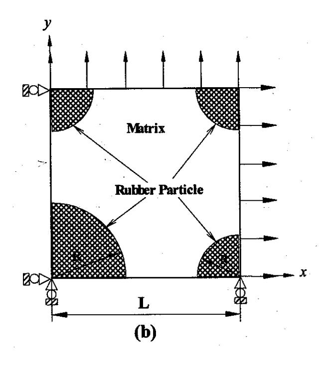
Fig. 1. Unit cell model. (a) Monomodal type (L = 0.1959 \(\mu\) m). (b) Bimodal type (L = 0.5958 \(\mu\) m).
Finite element meshes of the unit cell model for monomodal and bimodal types are shown in Figs. 2 and 3, respectively. Radius R of rubber particles is 0.1 \(\mu\) m for monomodal, and 0.1 \(\mu\) m and 0.25 \(\mu\) m for bimodal
type. A unit strain value in x directions \(\mathcal{E}_x\) and in y direction \(\mathcal{E}_y\) was applied to the element mesh with ratio \(\mathcal{E}_y/\mathcal{E}_x = 0.0\); 0.25; 0.5; 0.75 and 1.0. In this study, perfect bonding and debonding of the interface between the particle and the matrix is assumed in the computation.
Fig. 2. Finite element meshes of unit cell model for monomodal type (76 elements and 282 nodes).
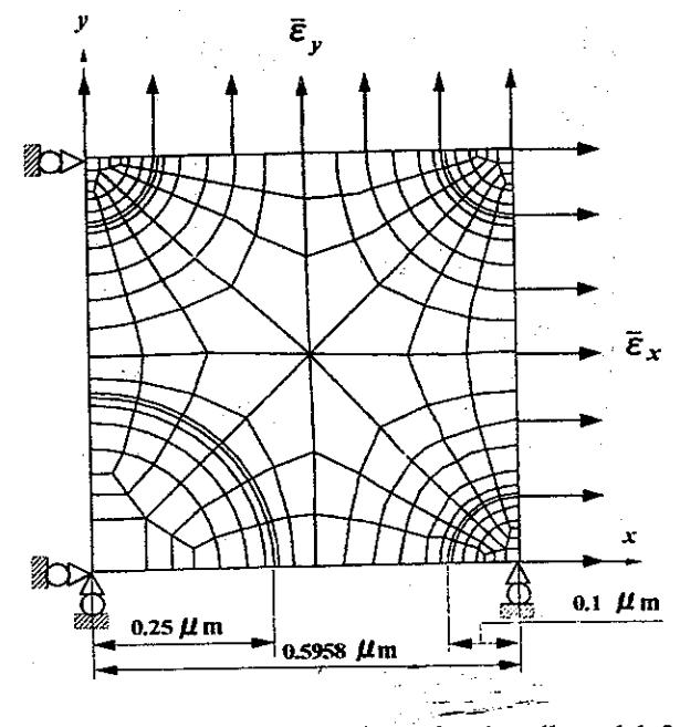
Fig. 3. Finite element meshes of unit cell model for bimodal type (242 elements and 877 nodes).
2. 2. Energy flux into fracture process zone \(\hat{J}\) -integral
The \(\hat{J}\)-integral, which is an extension of the J- integral [13] will be employed. Furthermore, the \(\hat{J}\)-integral is fully described elsewhere [14, 15], so that only a brief description will be given here.
We consider a two-dimensional crack as shown in Fig. 4 and assume that the crack tip moves virtually from the initial location 0 to the final location 0' with the distance 00' being infinitesimally small. \(0-X_1\), \(X_2\) is the fixed frame and \(0'-x_1\), \(x_2\) the moving frame whose origin 0' is coincident with the tip of the extending crack. The direction of \(X_2\) and \(x_2\) is perpendicular to the crack surface. It is assumed that fracture occurs in a fracture process region, or end region denoted by \(A_{\rm end}\) in which continuum mechanics does not work effectively. As shown in Fig. 4, \(\Gamma_{end}\) is the counter surrounding \(A_{\rm end}\), \(\Gamma_0\) any counter surrounding the end region, \(\Gamma_S\) curve along the crack surface, and A region surrounded by these curves. The energy-release rate due to crack extension is given by the \(\hat{J}\)-integral [14]:
\[\hat{J} = \int_{\Gamma} \left( -T_i \frac{\partial u_i}{\partial X_1} \right) d\Gamma + \int_{A-A_{end}} \sigma_{ij} \frac{\partial \varepsilon_{ij}}{\partial X_1} dA \quad (1)\] where the terms introduced have the meanings shown below.
\(\sigma_{\it ij}\): stress tensor,
\(\varepsilon_{ij}\): strain tensor,
T<sub>i</sub>: surface traction, ui : displacement,
\(\Gamma\): any curve surrounding the crack tip,
A \(\dot{}\) area surrounded by both curve \(\Gamma\) and crack surface.
Fig. 4. Configuration of crack tip with fracture process region and its boundary.
Note that the \(\hat{J}\)-integral does not lose the property of path-independence and its physical significance as energy release rate even for materials described by incremental plasticity theory, and that the \(\hat{J}\) value
almost coincides with the \(\hat{J}\) - value under monotonic loading conditions [14].
Figure 5 shows finite element mesh used for analyzing the near tip fields. Plane strain and small scale yielding conditions are assumed, and the displacement field designated by Mode I stress intensity factor is applied.
Fig. 5. Whole configuration of finite element meshes.
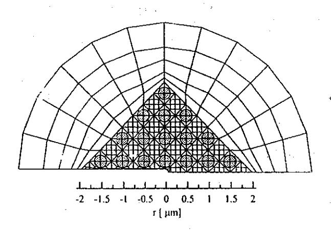
Fig. 6. Minute subdivision of finite element mesh (monomodal type).
The vicinity of the crack tip is modeled as composite of matrix materials and rubber particles as shown in Fig. 6. On the other hand, outer region is modeled as homogeneous material whose constitutive equation has been obtained by analyzing unit cell model of matrix and rubber particle. Perfect bonding of the interface is assumed in the computation. The finite element program takes into account the finite deformation. Matrix and rubber particles are treated as Mises and Mooney-Rivlin materials, respectively.
3. RESULTS
Young's modulus and Poisson's ratio obtained by finite element computation are shown in Tables 1 and 2, respectively. By comparing to the experimental results (Table 3), it shows that, the FEM computation results of Young's modulus a slightly different. However, Poisson's ratio values are almost similar.
Theoretical values of Young's modulus for composite model of matrix materials and rubber particle can be predicted by the following equation,
Parallel model,
\[E_c = E_f \cdot V_f + E_m \cdot V_m \tag{2}\]
Series model.
\[\frac{1}{E_c} = \frac{V_f}{E_f} + \frac{V_m}{E_m} \tag{3}\] where:
E<sub>c</sub> = average Young's modulus in the composite
\(E_m\) = Young's modulus of matrix (AS resin)
\(E_f\) = Initial tensile modulus of rubber material.
\(V_f\) = rubber volume fraction
\(V_m\) = volume of matrix.
Table 1: Young's modulus values obtain-ed by FEM computation.
| Young's modulus [GPa] | |||||||||
|---|---|---|---|---|---|---|---|---|---|
| \(\varepsilon_y/\varepsilon_x\) | |||||||||
| 0.0 | 0.25 | 0.50 | 0.75 | 1.0 | Mean | ||||
| Mono modal | 2.46 | 2.47 | 2.50 | 2.52 | 2.47 | 2.486 | |||
| Bimo dal | 2.44 | 2.52 | 2.55 | 2.58 | 2.52 | 2.522 | |||
Table 2: Poisson's ratio obtained by FEM computation.
| Poisson's ratio, \(\upsilon\) | ||||||||
|---|---|---|---|---|---|---|---|---|
| \(\varepsilon_y/\varepsilon_x\) | ||||||||
| 0.0 | 0.25 | 0.50 | 0.75 | 1.0 | Mean | |||
| Mono modal | 0.37 | 0.37 | 0.37 | 0.37 | 0.38 | 0.376 | ||
| Bimo dal | 0.38 | 0.37 | 0.37 | 0.37 | 0.37 | 0.377 | ||
Table 3: Experimental values of Young's modulus and Poisson's ratio.
| Material | E [MPa] | υ | |
|---|---|---|---|
| AS resin | 3710 | 0.35 | |
| ABS-1 (monomodal) | 2066 | 0.37 | |
| ABS-2 (bimodal) | 2310 | 0.37 | |
Comparison between theoretical values and FEM computation results of Young's modulus of AS resin toughened with rubber particles for monomodal and bimodal model without debonding is shown in Fig. 7.
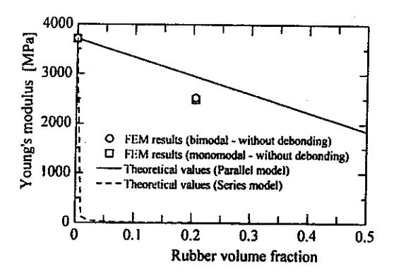
Fig. 7. Young's modulus - rubber volume fraction relationships.
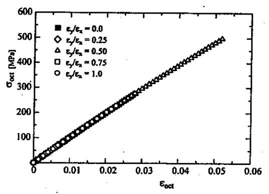
Fig. 8. Octahedral normal stress-strain relation of monomodal type.
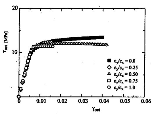
Fig. 9. Octahedral shear stress-strain relation of monomodal type.
Figures 8 and 9 show the octahedral normal and shear stress-strain relations for monomodal type, respectively. These relations are insignificant to the ratio of applied strain \(\mathcal{E}_y/\mathcal{E}_x\) since the bonding between the particle and matrix is generally considered perfect. Similar behavior is also found for bimodal type without debonding.
The shape of plastic region is shown in Fig. 10 where the yielded Gauss points are represented by dots. The solid line indicates shape of plastic region estimated by the elastic singular stress field. The shape of plastic
region is agreed well with this estimation in the perfect bonding case.
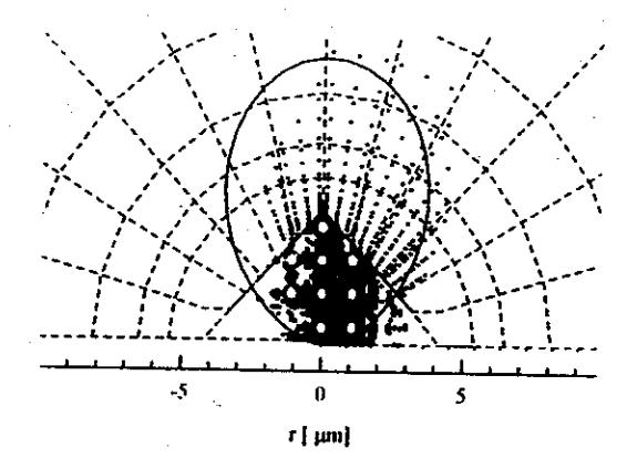
Fig. 10. Plastic zone (bonding case).
4. DISCUSSIONS
The following discussions concerning with the role of rubber particles in enhancing the fracture toughness in terms of \(\hat{J}\)-integral criterion. From experimental observations of ABS materials as described in the previous paper [2], the fracture toughness of ABS with bimodal type of rubber particles is larger than that of ABS with monomodal type of rubber particles content.
From the computational results, it can be extracted the relationship between the elastic energy release rate \(K_I^2/E'\), as the input energy far field from the crack tip, and the energy flux into process region \(\hat{J}\)-integral as shown in Figs. 11 - 14. Figure 11 shows that the \(\hat{J}\)-integral value for debonding a slightly reduced lower than for bonding case.
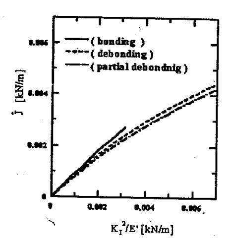
Fig. 11. Elastic energy release rate vs. \(\hat{J}\)-integral (monomodal particles size).
Moreover, the \(\hat{J}\)-integral value of partial debonding case decreases lower than that of for debonding. These behavior is also found in the bimodal model as shown in Fig. 12, but the value of \(\hat{J}\)-integral for partial debonding is greatly reduced.
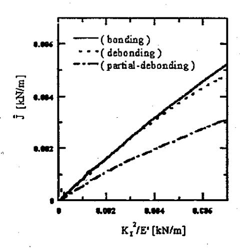
Fig. 12. Elastic energy release rate vs. \(\hat{J}\) -integral (bimodal particles size).
It is suggest that the screening effects of the rubber particles for energy flux into fracture process region occurred. The screening effect for bimodal model is largely occurred when the particles are partial debonding. In the bonding case both of monomodal and bimodal indicates that the flux energy into process region occurred at almost similar value of \(\hat{J}\)-integral as shown in Fig. 13. These phenomena imply that the influence of the screening effects of the rubber particles is not occurred.
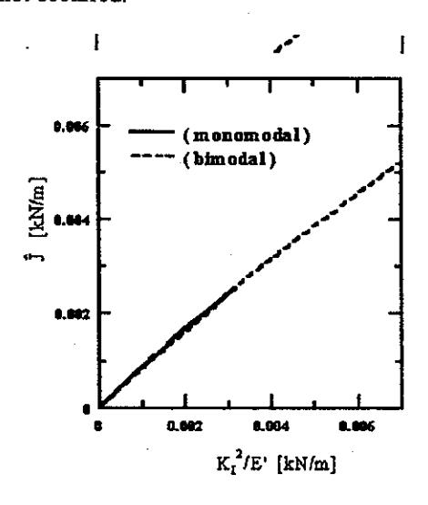
Fig. 13. Comparison of \(\hat{J}\)-integral for bonding case (monomodal and bimodal).
Figure 14 shows that the comparison of the \(\hat{J}\)-integral values between monomodal and bimodal model for partial debonding case. It can be observed that the screening effect of rubber particles occurred largely in bimodal model. Therefore, the fracture toughness of bimodal model is larger than that of for monomodal
model. In the calculation, size of debonding area is also considered. In the case of bimodal type, all rubber particles around the crack tip are partial debonded. The results show that, the screening effect of rubber particles due to the large size of debonding area lead to the energy flux into process zone becomes smaller than that of smaller size of debonding area as shown in Fig. 14.
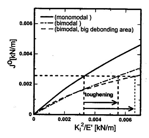
Fig. 14. Comparison of \(\hat{J}\)-integral for partial debonding case (monomodal and bimodal).
5. CONCLUSIONS
The effects of the distribution of rubber particle size on the fracture toughness for both monomodal and bimodal models have been performed by using FEM analyses .
To evaluate energy flux into process zone, the \(\hat{J}\)-integral has been computed. The following conclusions are extracted from these computations.
- 1. In the unit cell analyses, the octahedral normal and shear stress-strain relations are not sensitive to the ratio of applied strain \(\mathcal{E}_y/\mathcal{E}_x\) for the perfect bonding case. For partial debonding case, it was found that both monomodal and bimodal models show that greatly reduced the degree of octahedral stress or mean stress. In bimodal model for partial debonding of large particles, octahedral stress greatly reduced larger than that of small particles.
- The shape of plastic region near the crack tip for bonding case is agree well with that obtained estimated by the elastic singular stress field. On the other hand, for partial debonding, the plastic region moves ahead of the crack tip.
- 3. In the bimodal models, the rate of energy flux into the fracture process region \(\hat{J}\)-integral is smaller than that of monomodal model. This behavior largely occurred on the partial debonding case. These induced to screening effects of rubber particles. The screening effects of bimodal type are larger than that of monomodal type. Therefore, the fracture toughness of bimodal model is enhanced larger than that of monomodal model. However, for the perfect bonding case the value of \(\hat{J}\)-integral occurred at
- almost similar value. In this case the screening effects are not operate effectively.
- 4. The screening effect increases when the size of debonding area also increases.
Acknowledgements – The author would like to acknowledge Prof. Kikuo KISHIMOTO and Assc. Prof. Mitsuo NOTOMI for their help and discussions of this work when the research was conducted at their laboratory, Materials and Solid Mechanics Lab., Tokyo Institute of Technology, Tokyo, Japan.
6. REFERENCES
- T. L., Anderson, Fracture Mechanics: Fundamental and Applications, CRC Press, Boca Raton, Florida, (1991).
- Husaini, M. Notomi, K. Kishimoto, and T. Shibuya, Journal Materials Science Research International, Vol. 3, No. 3, pp. 158-165, (1997).
- 3. S. J., Shaw, In Rubber Toughened Engineering Plastics, A. A. Collyer, Ed., Chapman & Hall, London, p. 165, (1994).
- Y. Huang, D.L. Hunston, A. J. Kinloch, and C. K. Riew, In Toughened Plastic I, C. K. Riew and A. J. Kinloch, Ed., Advances in Chemistry Series 233; American Chemical Society: Washington, DC, , p. 1, (1993).
- 5. A. M. Donald, and E. J. Kramer, Journal of Material Science, Vol.17, p.1765, (1982).
- 6. G. H. Michler, and J. U. Starke, In Toughened Plastic II, C. K. Riew and A. J. Kinloch, Ed., Advances in Chemistry Series 252; American Chemical Society: Washington, DC, p. 251, (1996).
- A. J. Kinloch, and F. J. Guild, In Toughened Plastic II, C. K. Riew and A. J. Kinloch, Ed., Advances in Chemistry Series 252; American Chemical Society: Washington, DC, p. 1, (1996).
- 8. R. A. Hall, and I. Burnstein, In Toughened Plastic II, C. K. Riew and A. J. Kinloch, Ed., Advances in Chemistry Series 252; American Chemical Society: Washington, DC, p. 27, (1996).
- Y. Okamoto, H. Miyagi, M. Kakugo, and K. Takahashi, Macromolecules, Vol.24, p.5639, (1991).
- 10. X. H. Chen, and W. Mai, Key Engineering Materials, Vols. 145-149, p.233, (1998).
- K. Kishimoto, K., M. Notomi, and T. Koizumi, Book of Abstracts, 7th International Conference on Mechanical Behavior of Materials, The Netherlands Congress Center, The Hague, The Netherlands, pp.475-476, (1995).
- 12. H. Finney, and A. Kumar, Rubber Chemistry and Techn., Vol. 61, No. 65, pp. 879-891, (1988).
- 13. J. R. Rice, Transaction ASME, Ser. E., Journal Appied Mechanics, Vol. 35, pp. 379-385, (1968).
- 14. K. Kishimoto, S. Aoki, and M. Sakata, Eng. Fracture Mechanics, Vol. 13, pp. 841-847, (1980).
- S. Aoki, K. Kishimoto, and M. Sakata, J. App. Mech., Trans. ASME, Series E, Vol. 48 (2), pp. 428-429, (1981).