

M E S I N
Jurnal Teknik Mesin Vol. 22, No. 2, Oktober 2007 ISSN 0852-6095
Diterbitkan oleh : Program Studi Teknik Mesin,
Fakultas Teknologi Industri - ITB
Surat ijin : STT No. 964/DIT-JEN/PPG/STT/1982.
MESIN Vol. 22 No. 2 i
DAFTAR ISI
| Thermodynamic property model of wide-fluid phase n-butane. Chan Sarin, I Made Astina, Prihadi Setyo Darmanto dan Haruki Sato | 44-54 |
|---|---|
| Sifat mampu nyala dan massa optimum refrigeran campuran R-290/R-22 Sebagai alternatif pengganti R-22 | |
| Ari Darmawan Pasek, Aryadi Suwono, Novianti Nugraha dan Usman Rosyadi | 55-61 |
| Optimisasi proses pemesinan EDM wire cut untuk modus gerak sirkular menggunakan algoritma genetik. | |
| Sigit Yoewono Martowibowo dan Adriansyah | 62-68 |
| Effects of hydrogen addition into intake air on hydrocarbon emission of gasoline engines at cold start condition. | |
| Arief Haryanto, Wiranto Arismunandar dan Gerard George Engel | 69-72 |
| Particle size distribution and rheological characteristic of trimethylolethane treated by cationic surfactant. | |
| Yuli Setyo Indartono, Hiromoto Usui, Hiroshi Suzuki, Satoshi Tanaka, Kousuke Nakayama, Yohiyuki Komada dan Tetsu Itotagawa. Mu | 73-80 |
| Pemanfaatan system CAD/CAM/CAE dalam reverse dan forward engineering untuk turbin Francis. | |
| Indra Djodikusumo, Lukman Santoso dan Rahmat Haris. Mu | 81-89 |
M E S I N
Jurnal Teknik Mesin
Vol. 22, No. 2, Oktober 2007 ISSN 0856-6095
Yuli Setyo Indartono<sup>(1)</sup>, Hiromoto Usui<sup>(2)</sup>, Hiroshi Suzuki<sup>(3)</sup>, Satoshi Tanaka<sup>(2)</sup>, Kousuke Nakayama<sup>(2)</sup>, Yoshiyuki Komoda<sup>(2)</sup>, Tetsu Itotagawa<sup>(2)</sup>
(1)Mechanical Engineering Department, Institut Teknologi Bandung, Jalan Ganesha No. 10, Bandung, Indonesia, indartono@yahoo.com (2)Department of Chemical Science and Engineering (3)Graduate School of Science and Technology (2,3)Kobe University, 1-1, Rokkodai-cho, Kobe-shi, Hyogo, 657-8501, Japan.
Ringkasan
Suspensi yang terdiri dari partikel Trimethylolethane (TME) trihydrate dan air merupakan bahan yang tepat untuk digunakan dalam transportasi panas laten pada sistem-sistem pendingin. Hal tersebut dikarenakan TME memiliki kapasitas perpindahan panas dan kapasitas termal yang tinggi. Untuk menurunkan faktor gesekan sluri TME, ditambahkan aditif berupa oleyl bishydroxyethyl methyl ammonium chloride sebagai surfaktan dan sodium salisilat sebagai counter-ion. Dalam penelitian ini, dipelajari pengaruh aditif terhadap distribusi ukuran partikel dan karakteristik reologi TME. Hasil penelitian ini memperlihatkan bahwa aditif tidak mempengaruhi ukuran partikel pada titik kristalisasi, namun nampak jelas bahwa aditif tersebut menghambat pertumbuhan partikel. Bila rasio molar counter-ion terhadap surfaktan ditingkatkan, partikel-partikel TME tidak tumbuh sama sekali. Peningkatan konsentrasi TME pada campuran TME dan surfaktan, menurunkan viskositas nyata (apparent viscosity) dan meningkatkan laju geseran kritis untuk terjadinya struktur akibat geseran (Shear Induced Structure – SIS). Bila hasil penelitian ini dikaitkan dengan hasil penelitian sebelumnya, maka ditemukan hubungan antara SIS dan penurunan drag (draf reduction – DR) untuk sistem suspensi TME yang berkemampuan menurunkan drag.
1. INTRODUCTION
Energy scarcity and environment protection are two main issues that give new direction in air conditioning technology in the last decade. More energy-savings and environmental-friendly substances are common requirements for recent cooling systems. A district cooling system provides an opportunity to create high energy-savings and also maximal protection to the atmosphere, since this system uses very low amount of primary refrigerant to cover a very wide area. However, pumping power of this system consumes a lot of energy. Therefore, to maximize the energy efficiency of the system, a new secondary refrigerant with significant energy-saving potential should be used.
Trimethylolethane (TME) slurry is a suitable phase-change substance to be used in district cooling application. TME has high latent heat (218 kJ/kg) and non-corrosive against metals [1]. TME is considered as a non-hazard and non-toxic material. Temperature of TME hydrate formation can be adjusted by controlling its concentration. This is an important advantage of TME slurry over the ice slurry. Nucleation point of TME crystal can be set at higher
temperature than that of the ice. It means a refrigeration machine has a higher COP (Coefficient of Performance) when it produces TME slurry than the COP when it produces ice slurry.
Test of TME with oleyl bishydroxyethyl methyl ammonium chloride (Ethoquad O/12 from Lion Akzo)/ NaSal done by present authors confirmed that the surfactant can induce drag reduction in TME slurry [2]. Surfactant has an ability to recover its micelle structure in a recirculating system. That is the reason why surfactants are suitable for district heating and cooling system application.
For the majority of suspensions, apparent viscosity is a decreasing function of stress and shear rate (shear thinning or pseudoplastic) [3]. The primary factors that influence the viscosity of suspensions are: solids loading, particle size distribution, and chemical additives [3]. For a phase-change suspension, temperature has a very important effect on viscosity since the amount of particles in the suspension is highly depended on temperature. Thread-like micelles existence in the suspending medium of this TME suspension also gives important effect to the viscosity. Disturbance to the thread-like micelles will influence viscosity of drag-reducing TME.
During storage of hydrate particles suspension, there are three mechanisms responsible to alter crystal size and shape, i.e. attrition, agglomeration, and Otswald ripening [4]. Attrition is crystal damaging by collisions with other solids or crystals, agglomeration is the adherence of two small crystals resulting in a new - large crystal, while Otswald ripening is growth of large crystals due to surface energy contributions; small crystals have a lower equilibrium temperature than the large ones [4]. Recently, a technology for preventing the agglomeration and growth of ice particles in water has been developed by using very small amount of suitable additives, such as anti-freeze protein, silane coupling agents, and surfactant [5]. Absorption of the anti-freeze protein [6], silane coupling agents [7], and surfactant [8] onto the crystal surface is the mechanism responsible for prevention of the agglomeration and growth of ice particles.
This work focuses on the influence of the additives to the particle size distribution and rheological characteristics of TME. The additives used in this work are oleyl bishydroxyethyl methyl ammonium chloride (C18H35N(CH2CH2OH)2CH3Cl) 2000 ppm (as cationic surfactant) and sodium salicylate (HOC6H4COONa) (as counter-ion). The molar ratio
(MR) of counter-ion to surfactant was varied to investigate the counter-ion concentration effect to the particle size distribution and rheological characteristic of TME suspension system.
2. EXPERIMENTS
2.1 Particle size distribution
TME 25 wt% water solution (with and without surfactant) was prepared at room temperature and then was homogenized by a magnetic stirrer. MR was set at 1.5, 2, and 3. The samples then were cooled until 9 oC while it was stirred by an electric motor with axial-type impeller (at 100 rpm) to induce crystallization. After solid particles appeared, this fresh slurry then was moved quickly to a microscope equipped with a cooling machine. This first measurement is defined at t = 0. Schematic picture of the apparatus used for this measurement is shown in Figure 1. The temperature of cooling water was set at 5 oC. By using digital camera connected to the microscope, about 10 pictures at different locations were taken quickly for each sample. Particle size measurements were carried out for slurry at t = 0, 1, 2, 3, 4, 5, and 6 hours. For every time, t, the size of more than 700 particles (area-based equivalent diameter) was calculated by using COSMOS 32 image-processing software. Between the measurements, the slurry was kept in the glass cup covered by a flexible plastic to minimize surrounding disturbance.
2.2 Rheology
Stress-controlled rheometer, SR-5 from Rheometric Scientific Co. Ltd., was used to measure apparent viscosity of TME water solution at concentration of 15, 23, and 27.5 wt%, while for TME suspension at 23 and 27.5 wt% since at 15 wt% solid only occur at very low temperature. Two types of rheometer geometry, i.e. cone-and-plate (for solution) and parallel-plate (for suspension), were used in the measurement. Before measurement, the solution was kept between cone and plate for about 1 minute to ensure that thermal equilibrium was attained. Most measurements were conducted more than once to ensure data consistency. The MR was set at 1.5 and 3.
Figure 1. Schematic figure of apparatus used for particle size distribution measurement.
3. RESULTS AND DISCUSSION
3.1 Particle size distribution
The photographs of TME slurry 25 wt% (with and without additives at MR = 1.5) is shown in Figure 2.
Figure 2. Hydrate particles of TME 25 wt%: (a) t = 0 h without surfactant (b) t = 1 h without surfactant (c) t = 1 h with surfactant.
It can be seen in Figure 2 that there is a significant hydrate particle growth after one-hour of storage at constant temperature. Otswald ripening and agglomeration may be the main factors responsible for the growth. For both t = 0 and 1 hour, most of particles have square geometry. It seems that most particles grow in all directions – maintain their square form. When this slurry flows in a piping system, it is predicted that particle-fluid interactions can change the space occupied by the particles: from square (or cube in 3 dimensions) to circular (or sphere in 3 dimensions). Eventhough the particle size is still less than 1 mm, the growth of the particle will increase its pressure-drop in pipe installation. Particle growth from 0 to 6 hours is shown in Figure 3 (for clear presentation, only data at t = 0, 1, 2, 4, and 6 hours are presented).
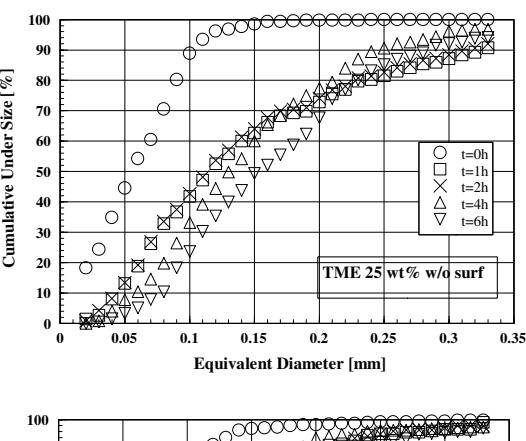
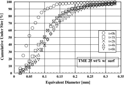
Figure 3. Particle size of TME slurry 25 wt% with and without surfactant 2000 ppm. MR = 1.5.
It can be seen in Figure 3 that the growth is decelerated after one-hour of storage. There is a possibility that the growth has approached a saturation condition for this concentration and temperature. Without surfactant, at cumulative under size of 90%, the hydrate particles grow from 0.1 to 0.3 mm. It can be predicted that such growth may affect flow condition significantly. By adding the additives into TME, the growth prevention occurs on the TME hydrate. The prevention seems to occur at all particle faces since most particles maintain their square (cube) geometry (see Figure 2). To see the influence of counter-ion concentration, particle size distribution of TME 25 wt% with the same additives at MR = 2 and 3 were measured. Both results are presented in Figure 4.
From Figure 4, it is clear that additional counter-ion gives more retardation to the particle growth. At MR = 3, the particles do not grow at all, while at MR = 2, the particles slightly grow. At cumulative under size of 50%, the influence of counter-ion concentration to the retardation of TME hydrate particle growth can be seen in Figure 5.
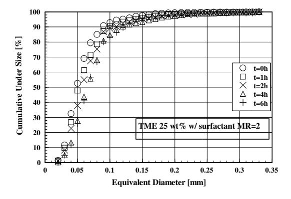
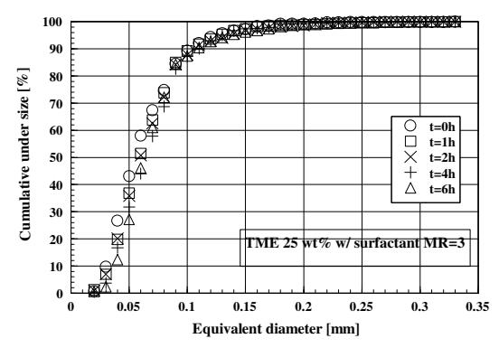
Figure 4. Particle size distribution of TME 25 wt% slurry with surfactant 2000 ppm. MR = 2 and 3.
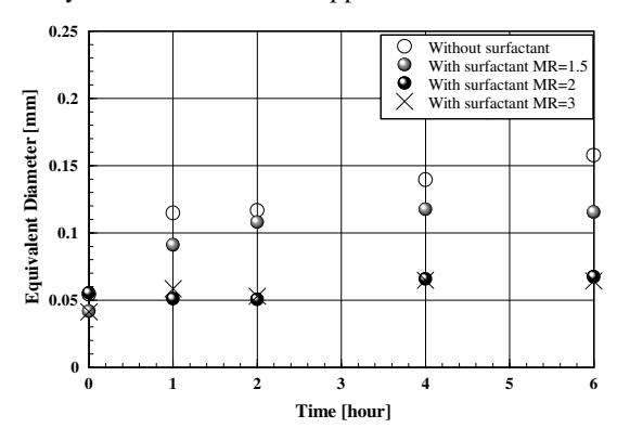
Figure 5.
Particle size of TME slurry 25 wt% with and without surfactant 2000 ppm at 50% cumulative under size as a function of time.
It can be seen in Figure 5 that surfactant does not affect hydrate particle size at t = 0 significantly. However, particle growth retardation by surfactant can be seen clearly from t = 1 to 6 hours. It means that surfactant does not influence particle nucleation; but it keeps the particles size during storage. It can be concluded here that the additives strongly influence TME particle growth. However, by using Orange II method, Suzuki et al. [9] found that no adsorption of surfactant (Ethoquad O/12) molecules occurs on TME hydrate particles. The particle-size control mechanism in this system may be different than that occurs on ice as previously investigated by some other researchers [6, 7, 8].
In another investigation [10], it was found that TME molecules reduce drag reduction (DR) capability of the surfactant. Low DR can be caused by less thread-like micelle network. By increasing the counter-ion concentration, DR capabilities are partly recovered [11]. It means, addition of counter-ion may responsible for thread-like micelle redevelopment (after it is disturbed by TME). Thus, counter-ion addition may responsible for denser thread-like micelle.
In a gas-liquid case, Lioumbas et al. [12] found that by adding small amount of surfactant into water solution, the thickness of liquid layer in co-current air-liquid is higher than that without surfactant. Spedding and Hand also report that the addition of very small quantities of polymer in water results in an increase of liquid layer thickness [12]. Lioumbas et al. [12] concluded that surfactant molecules accumulate at a region near the interface, increase the interfacial shear viscosity and create a layer which protects liquid from the gas's influence. Surfactant is also known for its ability to reduce gas transfer at gas-liquid interface [13, 14].
In this case, it is possible that surfactant thread-like micelles, which are concentrated at liquid-hydrate interface, influence liquid movement to the hydrate. This causes retardation on hydrate particle growth. Increasing counter-ion is responsible for denser thread-like micelle; denser micelle network gives more barrier to the particle growth. At MR = 3 used in this study, it seems there are enough surfactant micelles to prohibit hydrate particle growth. Thus, it is possible that a network of surfactant thread-like micelles exists in the interface region between the solution and the hydrate and inhibit the particle growth without necessarily being adsorbed by the hydrate surface.
3.2 Rheology
3.2.1 TME slurry (with and without surfactant)
Surfactant 2000 ppm (MR = 1.5) was added into TME 23 and 27.5 wt%. At low temperature, the hydrate particles appear in the solution. Apparent viscosities of the slurry at low temperatures are shown in Figure 6.
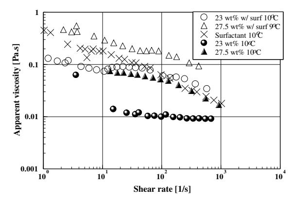
Figure 6. Apparent viscosity of TME slurry 23 and 27.5 wt% with and without surfactant.
At lower shear rate, the viscosity of surfactant solution is high (see Figure 6), possibly because there is dense micellar network in quiescent fluid. Lin et al. [15] observed micellar network microstructure by cryo-TEM and found that the density of the network increases with concentration. Thus, at high surfactant concentration, i.e. 2000 ppm, the denser network probably occurred in quiescent fluid. As shear rate is increased, the shear thinning behavior can be observed. Arrangement of micelle orientation by the shear may cause this shear-thinning tendency. At shear rate about 6 s<sup>-1</sup> there is an increase in the viscosity of surfactant solution; however, the increase is small. Hoffman and Rehage classified viscoelastic surfactant systems into two types. In the first and more general type, the structures causing viscoelastic behavior are present in the stagnant solution; in the second type, the viscoelasticity is observed only after a certain threshold shear rate is exceeded (shear-induced viscoelastic system) [16]. Hu and Matthys [17] found that in solution that is already quite viscoelastic at rest, the buildup of shear-induced structure (SIS) may not lead to further increase of viscosity and normal stress. It can be concluded that this surfactant solution maybe already quite viscoelastic at rest. That is why this surfactant does not show large viscosity jump-up.
As can be seen in Figure 6, the viscosity of suspension with surfactant is higher than that without surfactant. The high viscosity of suspending medium may be responsible for this high TME viscosity. By increasing the shear rate, the shear-thinning tendency occurred in the suspension, both with and without surfactant. In the surfactant solution, the increase of the shear rate causes micelle orientation arrangement in the flow direction, while in particles, the increasing shear rate may break the structure and agglomeration nature of the suspension; both effects contribute to the shear-thinning tendency. There is an interesting
phenomenon in Figure 6: SIS seems to occur in the suspension with surfactant, for both TME 23 and 27.5 wt%. This finding is consistent with a previous study that showed SIS phenomenon in TME slurry [9]. However, different than the jump-up in surfactant solution, the rate of shear thickening phenomenon in the suspension is slow. The SIS is clearer for 23 wt%, while the shear-thinning delay can be observed in 27.5 wt%. That slow thickening-rate may be caused by particle existence in the suspending medium. The SIS occurs at shear rate of 10 and 40 s<sup>-1</sup> for TME 23 and 27.5 wt%, respectively. It seems if TME concentration is increased, the critical shear rate also increases: this is similar to the temperature effect on critical shear rate for SIS occurrence in the surfactant solution [18].
3.2.2 TME solution (with and without surfactant)
Apparent viscosity of TME solution (with and without surfactant MR = 1.5) at 16 and 25°C can be seen in Figure 7. In liquid phase (without particles), the SIS phenomenon becomes more pronounced (see Figure 7). TME concentration effect on the critical shear rate can be seen clearly at 16°C. Similar to the previous slurry cases, i.e. when particles appear in the solution, the increase of TME concentration increases critical shear-rate. The critical shear rate for TME 15. 23, and 27.5 wt% are about 80, 300, and \(700 \text{ s}^{-1}\), respectively. It is also clear for these liquid systems that at constant shear-rate, the apparent viscosity is reduced by increasing TME concentration. Both phenomena: the critical shear-rate increase and the apparent viscosity decrease by adding more TME may be explained by a hypothese that TME existence changes surfactant thread-like micelle amount and length. Higher TME concentration may result in fewer and shorter thread-like micelles. Shorter thread-like micelles are responsible for higher critical-shear rate, while fewer micelle networks are responsible for lower apparent viscosity. In the previous work on the same surfactant solution used in this study, it was concluded that when the temperature is increased, the micelle length is decreased; resulted in higher critical shear rate [18].
At 25°C, the small jump-up still occurs in TME 15 wt% (with critical shear rate of 200 s<sup>-1</sup>), but it disappears in TME 23 and 27.5 wt%. This finding is consistent with the critical concentration of TME where SIS can be formed as proposed by authors [9]. It is also interesting to note that at about 10 and 16°C, DR occurs in TME 23 and 27.5 wt% [10] but disappears at 25°C [2], so does the SIS of those TME's obtained in this work: it occurs at about 10 and 16°C and disappears at 25°C. The same thing also
true for TME 15 wt% water solution: based on Figure 7, the SIS of TME 15 wt% occurred both at 16 and 25°C; in the other investigation, the authors [11] observed DR of TME 16.3 wt% at the same temperature.
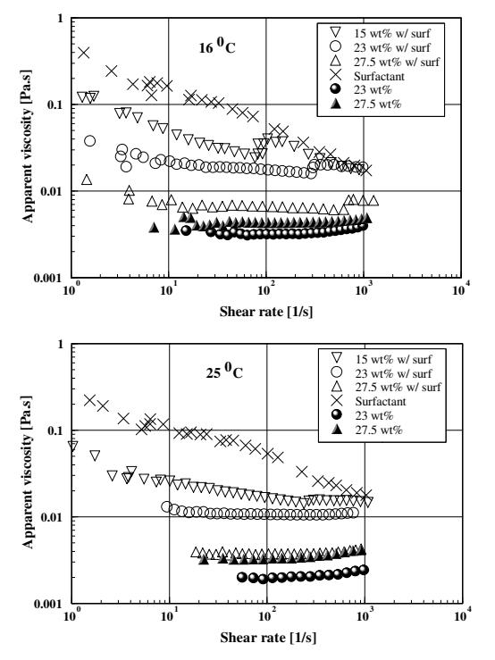
Figure 7. Apparent viscosity of TME 23 and 27.5 wt% (with and without additives at MR = 1.5) at 16 and \(25^{\circ}\)C as a function of shear rate.
3.2.3 Influence of the counter-ion concentration to apparent viscosity
To study the role of counter-ion concentration to TME with surfactant systems, TME 15, 23, and 27.5 wt% were treated with the additives at MR = 3. The apparent viscosities were measured by the same rheometer as before. Slurry viscosity was measured for TME 23 and 27.5 wt% since the slurry only appears at very low temperature for TME 15 wt%. Since influence of the counter-ion concentration is similar between TME 15, 23 and 27.5 wt%; only results of TME 15 and 27.5 wt% are presented in Figure 8.
From Figure 8, the apparent viscosities of TME slurry and solution with additives are increased when counter-ion concentration is increased. This tendency is opposite to that of counter-ion concentration influence to apparent viscosity of surfactant solution as shown in Figure 9.
As can be seen in Figure 9, the apparent viscosities of surfactant solution are reduced if counter-ion
concentration is increased. These are consistent with the previous work [19] that showed the optimum molar ratio between Ethoquad O/12 and NaSal to induce strong viscoelasticity is 1:1.5. The opposite behavior of TME with surfactant means that at MR = 1.5 the TME with surfactant does not reach an optimum condition for strongest viscoelasticity. TME molecules could influence interaction between surfactant and its counter-ion, so TME shift the optimum MR of the surfactant solution.
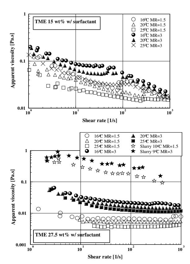
Figure 8. Apparent viscosity of TME 15 and 27.5 wt% as function of shear rate, temperature, and MR.
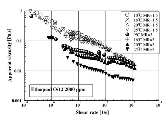
Figure 9. Apparent viscosity of surfactant solution as function of shear rate, temperature, and MR.
Adding more counter-ion to the drag-reducing TME may create denser thread-like micelle network and increase viscoelasticity. These also explain the influence of counter-ion addition to the particle size distribution: when MR is increased to 2 and then 3, retardation to the particle growth becomes stronger (see Figure 5). Denser thread-like micelle network and higher viscoelasticity may prevent the particles grow and agglomerate each other. This particle-size control mechanism may be different than that found by previous researchers.
4. CONCLUSIONS
The particle size distribution and rheological characteristic of TME treated with cationic surfactant were investigated in this study. Oleyl bishydroxyethyl methyl ammonium chloride was used as surfactant, while sodium salicylate as counter-ion.
TME hydrate particle exhibits a rapid growth from t = 0 to 1 hour; and then there is no significant growth until 6 hours of storage. Although surfactant does not affect particle size at t = 0 hour, it clearly inhibits further particle growth significantly. Increasing counter-ion concentration causes more retardation to the particle growth. At MR = 3, there is no particle growth at all.
From the rheological measurements, it is found that increasing counter-ion concentration causes a higher viscosity of TME with surfactant. Denser thread-like micelle network and stronger viscoelasticity may be responsible for that high viscosity. Both factors may also be responsible for strong suppression to the particle growth when MR is increased to 3. There exists a relation between SIS in rheological results and DR in this drag-reducing TME. It is interesting to note that the viscosity jump-up also appears in slurry with surfactant, even though the viscosity increasing is slower.
Finally it can be concluded from this study that the TME treated with drag-reducing additives at molar ratio (MR) = 3 is more appropriate to be used in energy-savings cooling system.