

1 INTRODUCTION
Energy scarcity and the environmental problems shift the cooling technology to the new direction: more energy-saving and environmentally-friendly. An indirect system, like a district system, has one cooling plant which delivers cooling fluid to the customer in a wide area. Chilled water is typical cooling fluid used in the district system. Ice slurry, a kind of phase-change material, getting more attention recently as an alternative for conventional chilled water. Since the invention of ice slurry technology in Russia about 80 years ago [1], many researches have been investigating better method for ice slurry producing, transporting, and improvement of its physical properties. However, in the ice-making of Cold Thermal Energy Storage (CTESs), the temperature of the evaporator is set conventional than significantly colder
air-conditioning systems, which leads to a lower performance of refrigerator [2]. In addition, if supercooling occurred in the ice-making, the evaporator temperature must be set at much lower position, which leads to further decrease of refrigerator performance. Saito [2] suggested researchers to develop a new phase-change material with a high melting point compared with ice.
Trimethylolethane (TME) slurry is a suitable phase change material to replace chilled water in a cooling system. The crystallization temperature of TME is higher compared with that of ice, i.e. about 9 and 13°C for TME 23 and 27.5 wt%, respectively [3]. It can be predicted that TME-slurry making process is more energy-efficient than the ice slurry. TME is non-flammable and non-corrosive against metals [4].
TME is considered as non-hazard and non-toxic material. These properties place TME as a suitable fluid for secondary refrigerant in a district system. However, compared with the high latent heat of ice, i.e. about 334 kJ/kg at 0°C, TME hydrate has a lower value, i.e. 218 kJ/kg (at 29.8°C for TME 62.5 wt%) [4].
To reduce the pressure drop of TME slurry, additives consist of cationic surfactant (oleyl bishydroxyethyl methyl ammonium chloride, trade name: Ethoquad O/12) and sodium salicylate (NaSal) are used as drag-reducing agent. Previous studies by authors [3, 5] show that the additives are able to induce an effective drag reduction in TME slurry. The additives also bring another important advantage to the TME slurry application in a district cooling system, i.e. control particle growth and agglomeration [6]. Since the amount of additives used in this system is very small, about 1,000 – 2,000 ppm (or 0.1 – 0.2%) and it is confined in the refrigerant circulation system, its effect to the human and environment may not be significant matter.
The drag reduction is simultaneously accompanied by heat transfer reduction (HTR) [3]. In the drag-reducing fluid, variation of streamwise heat flux increases, while normal heat flux decreases [7]. This HTR gives advantage on heat-loss prevention in fluid transportation, mainly for cooling system that serves very wide-area. In Germany, heat-losses in district heating can reach 13% of the total energy delivered by the system [8]. However, this HTR can degrade the overall heat transfer coefficient of a heat exchanger. Certain type of heat exchanger, for example that uses Barus effect, can avoid the heat transfer degradation, and even increase the heat transfer [9]. Gyr and Bewersdorff [10] suggested controlling the flow rate of a drag-reducing fluid so that the HTR disappears in heat exchangers. It should be noted that the thread-like micelle network is temporarily disrupted at high shear-rate. Some piping elements, such as elbow and pipe-reduction also temporarily disrupt the micelle network. Tagoku et al. [11] showed that friction factor of surfactant (Ethoquad O/12) solution after branch is higher than that before the branch. Gasljevic and Matthys [12] observed high friction factor and heat transfer coefficient near the pipe entrance. This special feature of the fluid is important to be considered when design a cooling system using the drag-reducing fluid.
By considering the above explanation, heat transfer coefficient in a small (individual) fan coil unit (FCU) with some piping-turn may not so severely reduced. Circulation of drag-reducing TME slurry from cooling plant until individual FCU gives two advantages: drag reduction and heat-loss prevention on piping systems. Particle growth controlled by the additive also an important added value of drag-reducing additive usage in TME slurry.
2 DESIGN A COOLING SYSTEM USES DRAG-REDUCING TME SLURRY
The main advantage of using a phase-change material is its high latent heat. Heat components of a phase-change material can be written in the following equation:
\[q = q_{sensible} + q_{latent}\] (1)
where q is total heat transfer occur in a fluid. For a constant specific heat, \(c_p\), Eq. (1) can be written as:
\[q = \dot{m}_s c_p \left( T_{out} - T_{in} \right) + \dot{m}_{pc} \Delta h_{latent}\] (2)
where \(\dot{m}_s\), \(\dot{m}_{pc}\), and \(\Delta h_{latent}\) is mass flow rate of the slurry, mass flow rate of hydrate exhibits phase change, and latent heat of the hydrate, respectively. \(T_{\rm out}\) and \(T_{\rm in}\) is slurry temperature exit from and enter to the heat exchanger, respectively. Mass flow rate of hydrate can be calculated by knowing the temperature-difference which is experienced by the slurry in the heat exchanger. TME phase-diagram developed by Kakiuchi et al. [4] can be used to calculate phase-change amount at certain temperature difference.
HPF is defined as a mass ratio between hydrate to the mixture. If the HPF difference is denoted as x, Eq. (2) can be formulated as:
\[q = \dot{m}_s \left[ c_p \left( T_{out} - T_{in} \right) + x \Delta h_{latent} \right]\] (3)
Eqs. (1) - (3) show the contribution of latent heat to the total heat transfer. Those equations also show that latent heat transportation needs lower mass flow rate compared with that of sensible heat to achieve the same amount of heat transfer.
The drag reduction of TME occurs in the installation can be estimated by using friction factor or drag reduction curves that have been investigated in the previous study [3, 5]. Extension of these results to a larger pipe-diameter can be done by apply some scale-up laws that were discussed and developed in previous studies [5, 13]. For clearer presentation, friction and Colburn j-factor of drag-reducing TME investigated in the previous study [3] are reloaded in this paper.
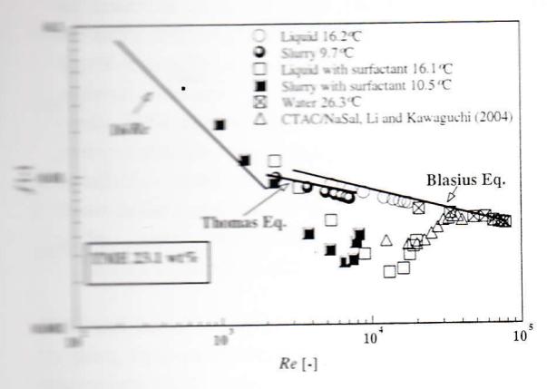
Figures 1 & 2 show friction factor and Colburn j-factor of TME with and without the cationic surfactant 2000 ppm (with molar ratio between counter-ion to surfactant is 1.5).
It is interesting to compare the friction factor and
The I Friction factor of drag-reducing TME
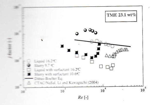
Figure 2 Colburn factor of drag-reducing TME
Coburn j-factor in Figures 1 & 2. Loss of HTR at critical Reynolds number, signed by the Colburn j-factor increase, is similar with the loss of drag reduction (DR), signed by the friction factor increase. The similar pattern of both figures pointed out that DR and HTR must be driven by the same mechanism. Similar with Gasljevic and Matthys [12] finding, there is a coupling between friction factor and heat transfer characteristic.
To get insight into the drag-reducing TME slurry performance in a fan coil unit (FCU), calculation of the overall heat transfer coefficient, U, in a FCU uses chilled water, TME slurry, and drag-reducing TME slurry are conducted. In this calculation, the FCU consists of 40 tubes (4 rows, 10 tubes per row) with inner and outer tube diameter is 13 and 18 mm, respectively. Tube length is 1 m, while tube arrangement is staggered. Longitudinal and transverse space between tubes is 37.5 and 45 mm, respectively. Circular fins with outer diameter of 40 mm, thickness 0.406 mm, and spacing 1.903 mm are used in this compact heat-exchanger. Tube material is copper, with aluminum fins. The cooling fluid flows inside the FCU. The fluid flow is divided into 10 tubes in each row. Air at 30°C flows at the outside of the FCU at velocity of 5 m/s. TME slurry with the same mass flow rate and temperature with chilled water is used as a comparison. The calculation result shows that when drag-reducing surfactant is added to the TME slurry, the heat transfer coefficient is reduced about 20% (with fouling resistance of 0.0005 \(\rm m^2 \cdot K/W)\)). This result is in agreement with Gasljevic and Matthys [14] experiment which found that drag-reducing surfactant causes about 20% heat transfer reduction in a cooling coil they observed.
By considering the aforementioned calculation, to energy-saving capability maximize the drag-reducing TME slurry, heat transfer enhancement in FCU is important to be done. Researchers proposed some methods to enhance heat transfer of drag-reducing surfactant in heat exchanger. Most of them rely on temporarily disruption or alternation of the surfactant micelle structure by mechanical means before the surfactant solution flow through the heat exchanger, so that the solution is "water like" in its behavior and provides high turbulent heat transfer coefficient; for example by using static mixer just before the heat exchanger [15]. Other method uses fluted tube-in-tube heat exchanger [16]. They reported that heat transfer coefficient increasing up to 1.4 times compared with that of water in straight tube.
3 COMPARATIVE STUDY OF DRAG-REDUCING TME SLURRY APPLICATION
Yik et al. [17] did a detail study about application of three schemes of water-cooled air conditioning systems in Hongkong. The three schemes are: [1] Centralized piped seawater supply for condenser cooling (CPSSCC), [2] Centralized piped seawater supply for cooling towers (CPSSCT), and [3] District cooling system (DCS). These three systems use seawater as cooling fluid in condenser of the refrigeration machines. Yik et al. [17] used chilled water as the secondary fluid/refrigerant in their systems. In this study, drag-reducing TME slurry will be used as another secondary fluid in the same district cooling system (DCS).
Yik et al. [17] planned five district cases with various building number and its cooling load, i.e. Case 1 (40 MW), Case 2 (80 MW), Case 3 (120 MW), Case 4 (160 MW), and Case 5 (200 MW). Flow-loop of secondary fluid in this district system consists of three parts: (a) Production line, (b) Distribution line, and (c) Building. Drag-reducing TME slurry affected energy consumption in production and distribution line, and a small part of energy consumption in the buildings (since air flow dominates the building's energy consumption).
Comparison between chilled-water DCS and drag-reducing TME slurry to serve the same cooling load is presented in Table 1. It is assumed that 50% drag reduction is occurred in piping systems that uses
drag-reducing TME slurry. This moderate assumption is taken by considering the Reynolds number and velocity of the slurry in this installation. Scale-up law which was developed in the previous studies [5, 13] are applied to estimate this drag reduction value. From Table 1, drag-reducing TME slurry contributes significantly to suppress the electricity consumption of production and distribution line. Energy reduction in "building total" is not so significantly affected by drag-reducing slurry since the air-flow consumes large amount of energy. Yik et al. [17] used air-handling unit (AHU) to produce cold air for the building. However, fan coil unit (FCU) which is directly supplied by drag-reducing TME may contribute in energy-savings further. Usibelly et al. [18] found that heat caused by fan contributes to 13% of the total cooling load in the case of the typical office building in Los Angeles.
The energy-savings caused by drag-reducing TME slurry in the production and distribution line can be seen in Figure 3. This figure shows a big energy-savings, i.e. 74%, of pumping power in the production and distribution lines by using drag-reducing TME slurry. However, since chillers and air-flow system in the building consume a large part of the total energy in this district system, the total energy-savings by using drag-reduction TME slurry is about 10%. Fan coil unit (FCU) usage, in spite of air handling unit (AHU), can save significant amount of energy.
The coverage area of a district system is usually limited by installation capability to serve very long pipe network.
Pressure drop of the installation is increased by length of the pipe. There exists a pressure limitation for the pipe; in turn, this limitation influences length and coverage area of a district system. Drag-reducing surfactant addition into TME slurry can increase the coverage area of this district system since the pressure-drop is reduced. From calculation based on Case 5, it was found that chilled-water system could serve 10.2 km² area, while drag-reducing TME slurry can serve up to 16 km².
In his conclusion, Yik et al. [17] concluded that DCS is the best alternative from energy-savings point of view. For Case 5 (200 MW cooling load), energy use intensity (EUI, kWh/m²) of individual direct seawater-cooled system with CPSSCC is 143. CPSSCT system is 148, while DCS is 115. The drag-reducing TME slurry suppresses EUI further to 105.6.
4 CONCLUSION
A comparative study between chilled - water and drag-reducing TME slurry usage in a district system was conducted in this study. It was shown that latent-heat component gives large contribution to the total heat transfer occurs in a phase - change slurry system. Mass flow rate of slurry needed by an installation can be considerably lower compared with
Table 1.a Annual electricity consumption of DCS uses chilled-water
| District cooling system | Case 1 | Case 2 | Case 3 | Case 4 | Cons 5 |
|---|---|---|---|---|---|
| Chilled-water system | - 4500 | Case 4 | Case 5 | ||
| Production loop pumps (MWh) | 486 | 961 | 1,530 | 2,150 | 2.700 |
| Distribution loop pumps (MWh) | 3,510 | 7,550 | 10,100 | 11,500 | 2,700 |
| Building total (MWh) | 13,500 | 26,900 | 40,400 | 53,800 | 67,300 |
| Seawater pumps (MWh) | 667 | 1,320 | 2,090 | 2,930 | 3,690 |
| DCS chiller (MWh) | 16,400 | 31,600 | 47,500 | 62,300 | 77,000 |
| Overall (MWh) | 34,500 | 68,400 | 101,600 | 132,700 | 162,800 |
| Overall EUI* (kWh/m²) | 122 | 121 | 120 | 117 | 115 |
Table 1.b Annual electricity consumption of DCS uses drag-reducing TME slurry 23wt%
| District cooling system | drag-reducing TME slurry 23wt% | ||||
|---|---|---|---|---|---|
| Case 1 | Case 2 | Case 3 | Case 4 | Case 5 | |
| DR TME system | |||||
| Production loop pumps (MWh) | 133.6 | 262,4 | 415.3 | 581.5 | 707.0 |
| Distribution loop pumps (MWh) | 912 | 1965.5 | 2616.4 | 725.9 | |
| Building total (MWh) | 12,981.5 | 25,960.5 | 2975.4 | 3154.7 | |
| Seawater pumps (MWh) | 38,937.5 | 51,911.3 | 64,884.6 | ||
| DCS chiller (MWh) | 667 | 1,320 | 2,090 | 2,930 | 3,690 |
| 16,400 | 31,600 | 47,500 | 62,300 | 77,000 | |
| Overall (MWh) | 31,094.2 | 61.108.5 | 91,559.2 | 120,698.1 | 149,455.2 |
| Overall EUI* (kWh/m²) | 109.9 | 108 | 107.8 | 106.6 | |
| *EUI is energy use intensity | 107.0 | 100.0 | 105.6 | ||
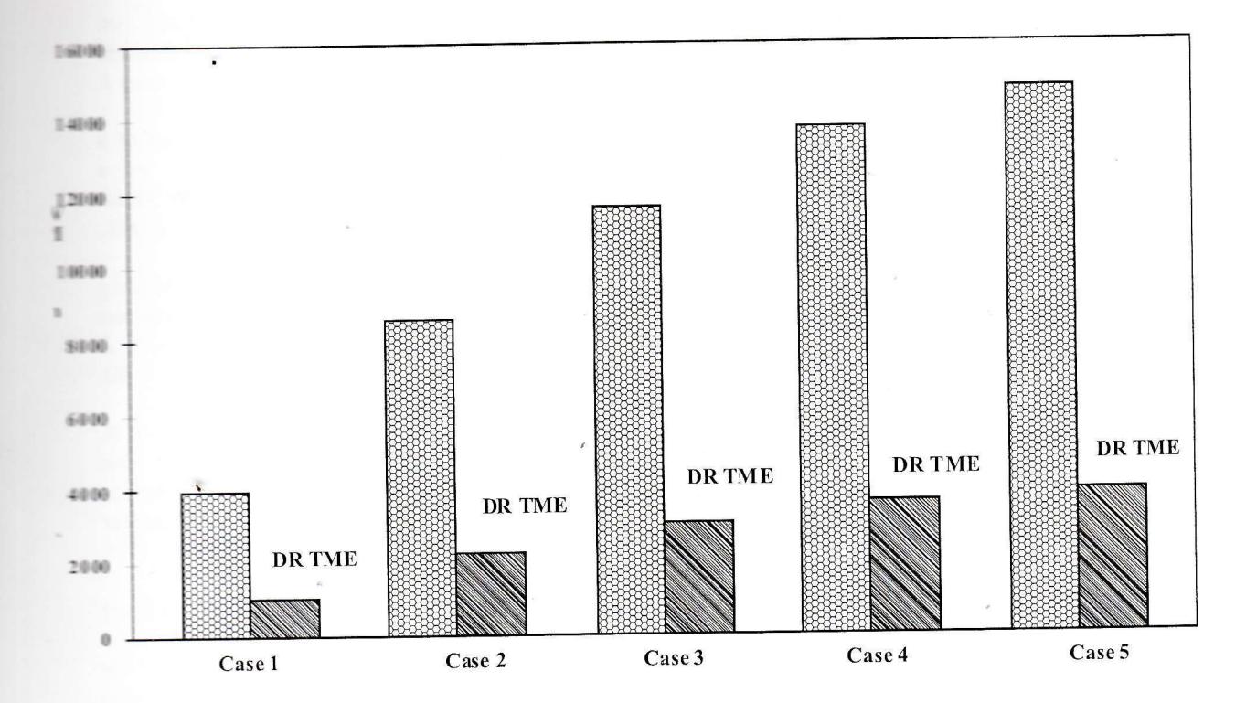
Figure 3 Annual electricity consumption (pumping power) of chilled-water and drag-reducing TME slurry 23 wt% in the production and distribution lines for five district system cases
that of single-phase fluid. This lower mass flow rate need less pump number and in turn reduces total pumping power required to circulate the fluid. Drag-reducing surfactant gives more suppression to the pumping power. surfactant contributes also drag-reducing significantly in heat-loss prevention, since the drag reduction is accompanied with heat transfer reduction. This heat-loss prevention can save large amount of energy. Comparative study done in a centralized system uses seawater-cooled system shows that drag-reducing TME slurry suppresses large amount of pumping energy in production and distribution line of the district system. Drag-reducing surfactant also contributes in maximizing the coverage area of the district system. Drag-reducing TME slurry which is supplied directly to the fan coil unit (FCU) can provide more energy-savings to the district cooling system. This scheme can maximize the slurry advantages, i.e. drag reduction and heat-loss prevention. Even though drag reduction causes big heat transfer reduction, but in reality the overall heat transfer
reduction may not so severely reduced since air-flow and fouling resistances in a heat exchanger can be considerably high. However, it is important to apply heat transfer enhancement technique for this drag-reducing TME slurry application in FCU.