

1 Introduction
These days, car plays an integral role in our life and becomes a part of the pattern of living. It can help us in various aspects such as: saving time, ease to travel and more comfortable. However, it also poses some issues in the event of accident. According to statistics, traffic accidents are considered as one of the most serious threats to human life [1]. Many research in crashworthiness area have been carried out theoretically, numerically and experimentally to make good predictions on the response of car structure in the crash events. However, majority of these investigations have not considered the effects of sheet metal forming during crash simulation. Without including the effects of forming process in crash simulation could lead to be inaccurate results. Hence, it is necessary to include the effects of sheet metal forming in the crash model to enhance the accuracy of simulation result. Majority of automobile components are made by stamping and deep drawing sheet metal process. Therefore, numerous studies have been conducted to study the effect of deep drawing process to the energy absorption performance of a structure made by such process. Doğan Uluğ Cağrı studied the effect of strain history on a full vehicle crash test simulation [2]. Simulation result was compared with test result of official website National Crash Analysis Center (NCAC). It was found that a good agreement with physical test in NCAC has been achieved. He concluded that sheet metal forming history should be taken into account to get more realistic result in FEM analysis.
Kim [3] from Kia Motors showed the influence of strain hardening and thickness change due to metal forming on the deformation and deceleration pulse for a full vehicle crash analysis. He concluded that more realistic results can be obtained by taking forming effects into account in the crash simulations.
Zoller and Frank [4] from Daimler Chrysler did a study to gain more exact predictions of displacements, stresses and strains from crash simulations and to save weight through a better optimized structure. By comparing the simulation results with and without forming history, they concluded that forming parameters (plastic strain and thickness distribution) have to be taken into account to predict the crash response realistically.
Simunovic and Aramayo [5] completed a study on steel processing properties and their effects on impact deformation of lightweight structures for the U.S. Department of Energy. Their research was mainly about the material models and effect of material properties on crash response. They pointed out that strain–rate material models give more accurate results than quasi–static material models. In addition, they stated that the forming effect should be taken into account with strain hardening materials in the computational crash models.
This paper reports the study of the effects of forming process to the crushing force characteristic of a top hat crash box subjected to axial crushing. First, deep drawing process which was used to form the crash box was simulated using HyperForm software. Forming parameters obtained from the simulations were then transferred to crash box model used in the crash simulation using LS– DYNA. The crushing force of the crash box which contains the forming effects were then compared to those without forming effects.
2 Geometrical Details
Figure 1 Crash box sample–dots represent the spot weld.
Geometrical details of the top-hat crash box being considered in this study is shown in Fig. 1. The column was made from two parts, the top hat profile which was made by forming process and the lid. Both parts were joined by welding. The thickness of the section is 2 mm.
3 Material Properties
The material of the crash box utilized in this study was mild steel RSt37. The static material properties were taken from the experiment conducted by Santosa et al. [6], i.e.: Modulus of Elasticity (E) 200 GPa, Yield strength (y) 215 MPa, Ultimate strength (u) 339 MPa, Poisson's ratio () 0.30, Density () 7.96×10⁻⁹ tons/mm3 and the power law exponent (n) 0.12. The true stress–effective plastic strain curve of RSt37 steel was calculated from the engineering stress–strain curve and is presented in Table 1.
Table 1 Engineering stress–strain curve [6].
| Mild Steel RSt 37 | ||||
|---|---|---|---|---|
| Effective plastic strain | True plastic stress | |||
| (%) | (MPa) | |||
| 0 | 251 | |||
| 2 | 270 | |||
| 3.9 | 309 | |||
| 5.8 | 339 | |||
| 7.7 | 358 | |||
| 9.8 | 375 | |||
| 1.14 | 386 | |||
| 1.32 | 398 | |||
The empirical Cowper–Symonds uniaxial constitutive equation constants were D = 6844 s-1 and p = 3.91. These constants were frequently used to define material behavior at different strain rate.
4 Finite Element Simulations without Forming Effects
Crush simulations were carried out component by using the multi–purpose explicit finite element software LS DYNA 971. The finite element model of the section are shown in Fig. 2. The Belytschko–Tsay shell elements were used to model column wall with mesh size of 5x5 mm. The nodes in the lowest cross section of the column were fixed. The material model of the mild steel was piecewise linear plasticity.
Figure 2 Finite element model.
The impactor was modeled using solid rigid elements. The impactor was only permitted to displace in vertical axis. Impact loading was given by using a 350 kg impactor which moved downward with a velocity of 8 m/s. The contact between the impactor and the column was nodes to surface. The contact used for the column wall was single surface to avoid interpenetration of folds generated during axial collapse.
Beam elements were used to model the spot–weld. Contact spot–welds were also used between the surface nodes and the spot–weld elements. The material model used to simulate the spot–weld was spot–welds with the same
mechanical properties of mild steel RSt37. Actually, after welding, the spot– weld area had different mechanical properties from the original properties of material. However, these differences were ignored in this study.
Fig. 3 and Fig. 4 give some results of crash analysis in terms of displacement, peak force and mean force for crash box without forming effects. Fig.4 shows that the maximum crushing force is 222 kN, which occurs in 0.6 ms, and the mean crushing force is 60 kN. The maximum displacement is 188 mm.
Figure 3 Deformation mode of top–hat profile without forming effect. (a) front view, (b) side view, (c) top view.
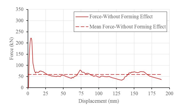
Figure 4 Force displacement of without forming effects model
5 Finite Element Simulations of Forming Process
5.1 Stamping
This is a process where a sheet metal, referred as blank, is formed by punch and die, which is fixed, to get final form [7]. First, binder and punch are lifted up above the blank. Then, the binder moves downward and clamps the blank so that the blank can be drawn inward. Finally, the punch also moves downward and the sheet metal is drawn through the opening of the die rig. Fig. 5 shows the tools for forming process.
Figure 5 Forming tools.
5.2 Material Model
In finite element forming simulations, the top–hat profile material was modeled as a transversely anisotropic elastic–plastic material (MAT 37). The punch, the die and the binder were assumed as rigid body.
5.3 Mesh
In order to obtain the accurate result and to save computational time, the method and the size of mesh were investigated carefully. In this study, initial mesh size of blank was 5 mm (Fig. 6). This mesh size was considered sufficient at the beginning however in the simulation of forming process there were some critical areas where the mesh sizes had to be made smaller to make sure degree of the accurate of result. Since it was difficult to know which areas were critical, adaptive remesh feature was utilized in this step.
Figure 6 Mesh refinement of top hat profile.
5.4 Load and Boundary Condition
Holder force, which was assigned to the binder to keep sheet metal right in place, had a magnitude of 100 kN. To reduce the dynamic effect, a rigid stopper was defined to limit the maximum velocity of the binder while the punch moved downward with velocity of 5000 mm/s. According to forming guideline, a trapezoid velocity profile was used, as shown in Fig. 7.
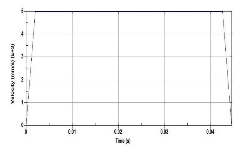
Figure 7 Trapezoid velocity profile.
5.5 Contact
One way forming surface to surface was used to define contact between the punch and the blank and between the blank and the die. Friction coefficient between the surfaces of components was 0.125.
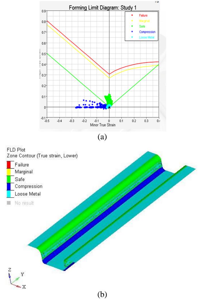
Figure 8 Forming limit diagram.
5.6 Forming Results
To observe whether model was safe or failed and check if wrinkle occurred, forming limit diagram was used, as can be seen in Fig.8. The red curve, which is obtained from experimental observation of the material, is the limit line. Area above this line is the failure area. In order to make sure that the model is safe, a yellow curve is presented as the failure boundary. Hence, it can be seen that the model is absolutely safe.
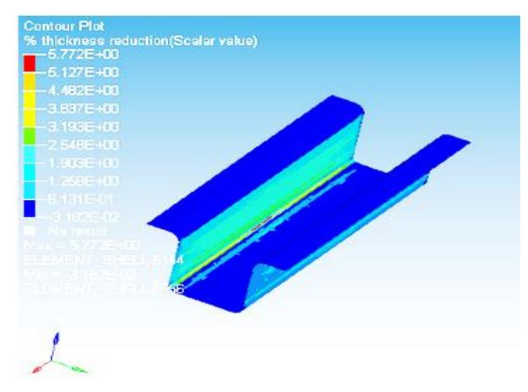
Figure 9 The percent thickness reduction.
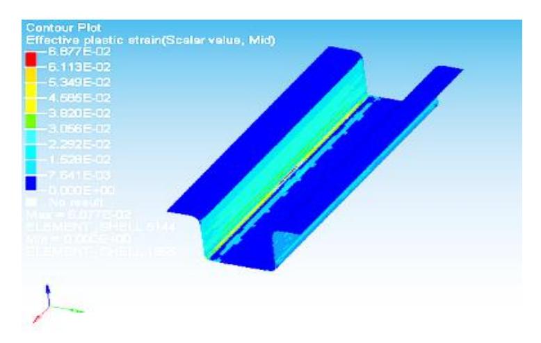
Figure 10 Effective plastic strain.
Fig. 9 and Fig. 10 show the results of forming process. The percentage of thickness change is 5.78 % and the maximum effective plastic strain is 6.9 %. After the forming simulation was completed, the basic data to be used as input for crash simulation was written out in a file called "dynain". This file contains the geometry (keyword CONSTRAINED_ADAPTIVITY), residual stress, effective plastic strain and thickness distribution of top–hat profile.
6 Crash Simulation with Forming Effect
6.1 Forming Result Mapping
The influence of sheet metal forming was mapped into crashworthiness model utilizing "dynain" file, obtained after forming simulation. The "dynain" file was included into the crash simulation by using *INCLUDE option in LS–DYNA and forming result was transferred from forming model to crash model. Then, crashworthiness simulation was conducted using the crash box model that already contained the forming effect parameters.
7 Impact Simulation with Forming Effect
7.1 Finite Element Model
The material model, load and initial boundary condition are the same with crash simulation without forming effect.
7.2 Result of Crash Simulation with Forming Effect
Fig. 11 and Fig. 12 present the results of simulations in terms of displacement, peak force, and mean force for the crash box containing forming effects. The maximum force is 293 kN, obtained in 0.5 ms. The maximum displacement of top–hat profile, subjected axial load is 158 mm. Meanwhile, mean force is calculated 71 kN.
Figure 11 Deformation mode of top hat profile with forming effect.
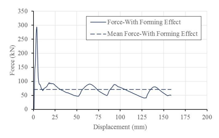
Figure 12 Force displacement diagram of forming effect model.
8 Comparison Result Between with and without Forming
Figure 13 Deformation mode of crash box with and without forming effect.
Fig. 13 and Fig. 14, shows that crash simulation using model containing forming effects has higher crushing force and lower displacement than that without forming effect. The model with forming effect is stiffer than one which does not include the manufacturing process.
Table 2 shows the maximum and the mean crushing forces for both simulations. It can be seen that for crash box containing forming effects, the peak crushing force is 24.2% higher and the mean crushing force is 15.5% higher than those without forming effects. The strain hardening on material in the manufacturing process increases the yield strength of the material. This makes the column model containing the forming effects is stiffer than that without forming effects.
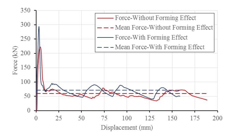
Figure 14 Diagram of Force displacement between with and without forming.
| Crash box | Crushing force (kN) | |||
| Max (%) Mean (%) | ||||
| Without forming effects 222 | - | 60 | - | |
| With forming effects | 293 | 24.2 | 71 | 15.5 |
Table 2 Crushing force comparison.
9 Conclusion
The effect of deep drawing as one of the process used to form crash box has been introduced in the crash analysis of the crash box. The results of the simulations show that the deep drawing process give a considerable influent to the crushing force characteristics of the crash box. In the simulations, the effects of forming process increase the peak crushing force by 24.2% and increase the mean crushing force by 15.5%.
Acknowledgement
The authors gratefully acknowledge financial support for this work from the AUN/SEED-Net (ASEAN University Network / Southeast Asia Engineering Education Development Network) and Indonesian Ministry of Research Technology and Higher Education, under the scheme of Decentralization Grant, Fiscal Year 2016. The authors also would like to thank to LSTC for providing an academic license of LS-DYNA.