

1 Introduction
In the daily life, walking is the most common activity. Walking movement is actually a complex activity since it involves many body parts, especially the lower
limb. Therefore, the walking movement or gait analysis is required to find the gait parameters, such as spatio-temporal, kinematics and kinetics parameters. The gait parameters are very useful in the medical application. There are some abnormalities that could be diagnosed by gait analysis, i.e. scoliosis [1], varus/valgus knee deformity [2], asymmetrical of body part [3], and nerve damage due to diabetes [4].
Due to the many needs of the gait analysis in medical applications, Biomechanics Research Team at the Faculty of Mechanical and Aerospace Engineering of Institut Teknologi Bandung (FMAE – ITB) has developed an affordable optical motion analyzer starting from two-dimensional (2D) system in 2008 to 2010 [5]. Then, the developed 2D motion analyzer system was used to collect Indonesian normal gait database in 2011 [6]. In order to obtain more complete gait parameters, the motion analyzer was further developed to three-dimensional (3D) system in 2011 – 2013 [7, 8]. The 3D motion analyzer system was then used for gait analysis of subject with scoliosis in 2014 – 2015 [9]. One of the disadvantages of the developed 3D motion analyzer system is the subject has to walk on the ground. Thus, the motion analyzer system could not be used for gait analysis that require many walking cycles due to limited capture area of camera. One of the ways to solve this problem is to use treadmill as the walking path [10]. Therefore, this paper presents the modification of the developed motion analyzer to accommodate the use of treadmill [11].
Beside the modification of the motion analyzer system, this study is also extended to its application in obtaining gait parameters of amputee subjects since the gait parameters of amputees are useful in the prosthetic development [12]. Prior to its application for amputees, the protocol and procedure of obtaining gait data is required since amputees are more likely fall down while they are walking. Therefore, the arrangement of protocol and procedure of gait analysis for amputees become an additional purpose of this study [13].
2 Methodology
The motion analyzer system in the previous study [8] used two cameras that were connected to the frame grabber in the workstation. The cameras used in the system were Sentech STC-CLC33A with the speed 95 frames per second. The frame grabber employed in the system were Dual-channel Camera Link Acquisition NI PCIe-1430. Both cameras and frame grabber is still being used in this study. The difference of present system with the previous one is the walking path. Richter Axiom® treadmill is used in the present study as the walking path. This treadmill has the speed range from 1 km/jam to 13 km/jam and inclination range 1 – 12%. All the equipment used in this study are arranged as shown in the Figure 1.
Since the developed system is also used for lower extremities amputee subject, the additional equipment for safety which is modification of hydraulic engine crank is included to the system which is shown in the Figure 2a. The hydraulic engine crank is modified in the arm and crank part. The arm is extended to the middle of the treadmill. Then, the crank is modified to be able attach the body harness (see Figure 2b). In the data acquisition, the body of amputee subject is supported by the body harness to reduce the risk of falling down.
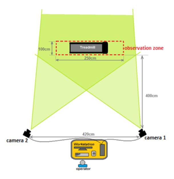
Figure 1 Set-up experiment
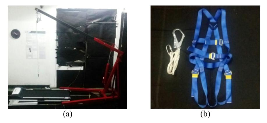
Figure 2 The additional equipment which consists of (a) Modified hydraulic engine crane and (b) body harness
Prior to data acquisition by cameras, seven active LED markers are attached on the metatarsal head, malleolus, calf, knee, femoral, hip, and Anterior Superior Iliac Spine (ASIS) of one-side foot based on the Kit Vaughan marker configuration [14]. Figure 3 presents the attached marker on the subject. This marker placement is also applied for the amputee subject.
Figure 3 The marker placement on the metatarsal head (p1), malleolus (p2), calf (p3), knee (p4), femoral (p5), hip (p6), and ASIS (p7)
Figure 4 The marker placement on the belt of treadmill
In the development of motion analyzer system with treadmill, the velocity of treadmill shown in the treadmill display should be evaluated. In the velocity evaluation, the length of treadmill belt was measured by the help of tape, as indicated in the Figure 4. As the result, the length of the belt was 2.7 meter. To measure the belt speed, a white tape marker was attached on the belt and the treadmill was operated in the certain speed. Then, the movement of the marker was recorded by a 95-fps camera to get the time for one cycle marker movement. By calculating the number of frames in one cycle, the period and speed of belt is obtained. The result shows that the speed displayed on the treadmill is similar with the measured speed.
Since treadmill is used in the present system, the marker trajectory recorded by cameras will be in the cycle diagram. However, it is difficult to determine the gait parameter, especially the parameter which is related to the walking direction (xaxis). Therefore, the marker trajectory is transformed by Equation 1 as below:
\[x_{i,new} = x_{i,treadmill} + \left[ \frac{v_{treadmill} \times 3.6}{v_{camera} \times 100} \times (i-1) \right]\] (1)
where xi,new denotes the marker position in the x-axis for i-th frame, xi,treadmill is the marker position in x-axis on the treadmill walking recorded by cameras for ith frame, vtreadmill and vcamera denotes the speed of the treadmill in km/hour and cameras in frames per second, respectively.
Figure 5 The measurement of anthropometric data [14]
In general, the procedure of data acquisition is selecting the subjects based on their medical history, giving the details about the purpose and procedure of data acquisition, preparing the data acquisition, recording the marker motion, measuring the anthropometric data, and processing the data. The anthropometric data to be measured is the body weight, height, and the body parameters described in the Figure 5. For the amputee subjects, there are several additional required
data, such as amputation level, amputation cause, walking aid other than prosthetic, design of structure (exoskeleton or endoskeleton), socket type, suspension type, and prosthetic type [15].
Table 1 Anthropometry parameters
| Anthropometry Parameters | Normal Participants | 3 Amputee | |
|---|---|---|---|
| 37 Male | 31 Female | Participants | |
| Age | 22 | 21 | 32.3 |
| Weight | 60.7 | 52.3 | 51.8 |
| Height | 1.69 | 1.57 | 1.63 |
| BMI | 21.2 | 21.3 | 19.4 |
| ASIS breadth (m) | 0.28 | 0.29 | 0.27 |
| Upper thigh diameter (m) | 0.18 | 0.15 | 0.14 |
| Midthigh circumference (m) | 0.47 | 0.46 | 0.44 |
| Thigh length (m) | 0.39 | 0.39 | 0.33 |
| Knee diameter (m) | 0.11 | 0.10 | 0.11 |
| Calf circumference (m) | 0.36 | 0.35 | 0.34 |
| Calf length (m) | 0.41 | 0.37 | 0.40 |
| Malleolus width (m) | 0.08 | 0.08 | 0.09 |
| Foot breadth (m) | 0.11 | 0.10 | 0.10 |
| Malleolus height (m) | 0.08 | 0.07 | 0.08 |
| Foot Length (m) | 0.25 | 0.24 | 0.27 |
The present system and data acquisition procedure is then employed to obtain the gait parameters from 37 male and 31 female subjects who do not have any abnormality. The gait parameters from three male amputee subjects are also measured to compare with the gait parameters of the normal subjects. All the amputee subjects have the trans-femoral amputation which is caused by train and motorcycle accident, and congenital condition. The amputee subject 1 and 2 have their left foot amputated. Then, the right foot of amputee subject 3 was amputated. Table 1 summarizes the anthropometric data of the subjects. The anthropometric data of amputee subjects are measured on their sound foot.
In the data acquisition, all the subjects walk on the treadmill with their comfortable speed. The markers attached on the right foot of normal subjects. However, since the walking pattern of sound and prosthetic foot may be different, there are two data acquisitions for the amputee subjects, i.e. when the markers are attached on the sound foot and on the prosthetic foot.
3 Result and Discussion
Based on the marker trajectory that has been transformed using Equation 1, the spatio-temporal of the subjects could be obtained. Table 2 presents the spatio-temporal parameters of the normal and amputee subjects. The parameters of over ground walking from the study conducted by Chandra et al. [8] is used as a comparison. Note that the parameters on the sound and prosthetic foot of amputee are obtained when the markers are attached on the sound and prosthetic foot of amputee subjects, respectively.
Treadmill Walking Overground [8] Amputees (Male) Parameter Normal Normal Normal Normal Sound Prosthetic Female Male Female Male Foot Foot Cadence (step/min) 98 97 93.16 96.86 90 96 Cycle time (s) 1.23 1.26 1.30 1.26 1.34 1.25 Stride length (m) 1.24 0.87 0.66 0.59 1.18 1.12 0.49 Walking speed (m/s) 1.01 0.69 0.52 0.88 0.91
Table 2 The spatio-temporal parameters of gait analysis
As shown in the Table 2, there is decrease in the stride length of the normal female subjects from the over ground walking to the treadmill walking. Moreover, the cadence in the walking movement is increasing while the subjects are walking on the treadmill. The change of the cadence and stride length of subjects possibly due to the walking adaptation of the subjects on the treadmill. As the result, they tend to increase their stride length and decrease their cadence.
The adjustment of the walking movement of amputee subjects could be also observed in Table 2. The amputees tend to shorten their stride length and slow down their cadence. As the result, the walking speed of amputees is slower than the walking speed of the normal subjects. Furthermore, the cadence of sound foot is slower than that of prosthetic foot. This result shows that the amputees tend to use their sound foot to support their body in the stance phase of walking. Therefore, the cycle time of sound foot is shorter than the cycle time of prosthetic foot.
Beside the spatio-temporal parameters, the effect of using treadmill in the kinematic parameters is also evaluated. Figure 6 presents the hip angle for the treadmill and over ground walking. The hip angle shows that the subjects who walk on the treadmill and on the ground, have similar pattern of hip angle.
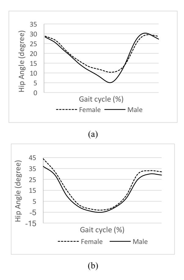
Figure 6 The hip angle of normal subjects in the (a) Treadmill, (b) Overground walking
However, the range of hip motion in the treadmill walking is smaller than that in the over ground walking. This result is due to the subjects in the treadmill walking tend to shorten their step on the moving belt [16]. Similar to the spatio-temporal parameter, the kinematic parameters between normal and amputee subjects is also different, as shown in Figure 7. Figure 7 presents the right and left hip angle in the sagittal (Figure 7a and 7b), frontal (Figure 7c and 7d), and transversal plane (Figure 7e and 7f). Note that S and P denotes the kinematics parameter of the sound foot and prosthetic foot, respectively. Figure 7a and 7b show that the pattern of the hip angle in the sagittal plane for the normal and prosthetic foot is same. However, there are phase shifting and the amputee subjects have larger range of motion compared to the normal subjects. This difference in the range of motion implies that there is an extra work done by the residual limb in doing walking movement. This condition could be found also in the Figure 7c and 7d. In the Figure 7e and 7f, it can be seen that the pattern of hip angle from the sound and prosthetic foot is different. Moreover, the prosthetic foot tends to have larger range of motion than the normal foot. This fact shows that the amputee subjects try to balance their walking on the treadmill.
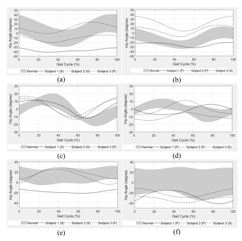
Figure 7 The hip angle for normal and amputee subjects: (a) Right hip angle in the sagittal plane, (b) Left hip angle in the sagittal plane, (c) Right hip angle in the frontal plane, (d) Left hip angle in the frontal plane, (e) Right hip angle in the transversal
4 Conclusion
This paper presents the modification of motion analyzer system developed by Biomechanics Research Team of ITB. The walking path in the previous system was the over ground walking. Then, the system is modified to the treadmill walking. Therefore, the modification of the system includes the transformation of the marker trajectory. Moreover, the system is modified also to be able used by amputee subjects. For that purpose, several additional safety equipment are included into the system, such as the modified hydraulic engine crane and the body harness. Prior to data acquisition, the speed of treadmill is confirmed. The modified motion analyzer system is then used to obtain the gait parameter of normal (37 males and 31 females) and three amputee subjects. Then, the gait parameters of normal subjects on the treadmill walking are evaluated and found that there is decrease in the stride length and increase in the cadence. The change of the cadence and stride length of subjects possibly due to the walking adaptation of the subjects on the treadmill. Besides, the range of hip motion in the treadmill walking of normal subjects is smaller than that in the over ground walking. This result is due to the subjects in the treadmill walking tend to shorten their step on the moving belt. The gait parameters of amputee subjects in the treadmill walking shows that the amputees tend to use their sound foot to support their body in the stance phase of walking. Moreover, the phase shifting and increase in their range of motion of hip angle implies that there is an extra work done by the residual limb in doing walking movement and the amputee subjects try to balance their walking on the treadmill.
5 Acknowledgement
Authors gratefully acknowledge the support of Ministry of Research Technology and Higher Education who have made this work possible through Penelitian Unggulan Perguruan Tinggi (PUPT) scheme research grant for year 2015 – 2017. The authors would also to acknowledge the help of Panji Firdaus and Kristofora Alvin Fenia in the present work. Finally, the authors would also like to thank volunteer amputees for their participation in this project as well as for their valuable inputs.
6 References
- [1] Kramers-de Quervain, I. A., Müller, R., Stacoff, A., Grob, D., & Stüssi, E., Gait analysis in patients with idiopathic scoliosis, European Spine Journal, 13(5), pp. 449 – 456, 2004.
- [2] Silva, H. G. P. V. D., Cliquet Junior, A., Zorzi, A. R., & Miranda, J. B. D., Biomechanical changes in gait of subjects with medial knee osteoarthritis, Acta Ortopedica Brasileira, 20(3), pp 150 - 156, 2012.
- [3] LaRoche, D. P., Cook, S. B., & Mackala, K., Strength asymmetry increases gait asymmetry and variability in older women, Medical and Science in Sports & Exercise, 44(11), pp. 2172 - 2181, 2012.
- [4] Katoulis, E. C., Ebdon-Parry, M., Lanshammar, H., Vileikyte, L., Kulkarni, J., & Boulton, A. J., Gait abnormalities in diabetic neuropathy, Diabetes Care, 20(12), pp. 1904-1907, 1997.
- [5] Mahyuddin, A. I., Mihradi, S., & Dirgantara, T., Development of an affordable system for 2D kinematics and dynamics analysis of human gait, Fourth International Conference on Experimental Mechanics. Vol. 7522. International Society for Optics and Photonics, 2010.
- [6] Mahyuddin, A. I., Mihradi, S., Dirgantara, T., Moeliono, M., & Prabowo, T., Development of Indonesian gait database using 2D optical motion analyzer system, ASEAN Engineering Journal 2.2, pp. 62-72, 2012.
- [7] Mihradi, S., Ferryanto, Dirgantara, T., & Mahyuddin, A. I., Development of an optical motion-capture system for 3D gait analysis, 2nd International Conference on Instrumentation, Communications, Information Technology, and Biomedical Engineering (ICICI-BME), 2011, IEEE.
- [8] Chandra, D., Anggraeni, N.D., Dirgantara, T., Mihradi, S. and Mahyuddin, A.I., Improvement of three-dimensional motion analyzer system for the development of Indonesia gait database, Procedia Manufacturing, 2, pp. 268-274, 2015.
- [9] Sugiharto, A., Dirgantara, T., Mihradi, S. and Mahyuddin, A. I., Investigation of Upper Body Motion of Subject with Spinal Abnormalities During Gait, The 7th AUN/SEED-Net Regional Conference in Mechanical and Manufacturing Engineering 2014 (RCMME 2014), Hanoi, October 9- 10, 2014.
- [10] Kimberly, A. Instrumented Treadmills: Reducing the Need for Gait Labs (2007).
- [11] Firdaus, P., Pengembangan Sistem Analisis Gait Tiga Dimensi untuk Subjek Berjalan di Treadmill, Bachelor Thesis, Faculty of Mechanical and Aerospace Engineering, Institut Teknologi Bandung, Bandung, 2016.
- [12] Yoo, J. C., Ahn, J. H., Kim, J. H., Kim, B. K., Choi, K. W., Bae, T. S., & Lee, C. Y., Biomechanical Testing of Hybrid Hamstring Graft Tribial Fixation in Anterior Cruciate Ligament Reconstruction, The Knee, 13 (6), pp. 455-459, 12 (2016).
- [13] Fenia, K. A., Penyusunan Protokol Pengujian dan Analisis Gait 3 Dimensi untuk Subjek Normal dan Lower Extremity Amputee Berjalan di Atas Treadmill, Bachelor Thesis, Faculty of Mechanical and Aerospace Engineering, Institut Teknologi Bandung, Bandung, 2017.
- [14] Vaughan, C.L., Davis B.L., & O'Connor J.C. Dynamics of Human Gait (2nd ed.). Cape Town: Kiboho. (1999)
- [15] ISPO. Recommendation for Defining Participants in Prosthetics Research, 2013.
- [16] Stolze, H., Kuhtz-Buschbeck, J. P., Mondwurf, C., Boczek-Funcke, A., Jöhnk, K., Deuschl, G., & Illert, M., Gait analysis during treadmill and overground locomotion in children and adults, Electroencephalography and Clinical Neurophysiology/Electromyography and Motor Control, 105(6), pp. 490-497, 1997.