

1 Introduction
The blastworthy structure is an ability of a structure to deform under controllable force and maintain sufficient residual space for the occupants to minimize injury during blast impact incident. In the application of blastworthy structure, the occupants of armored vehicle (AV) need to be protected from landmines and improvised explosive devices (IEDs). The high fatality number of military personnel in Iraq and Afghanistan is 35-40% caused by IEDs [1]. The protection strategy by stiffening the floor structure using an add-on construction is important to reduce force and acceleration on the occupant space. The requirements for the add-on structure are lightweight for easy mobility and stiff enough to counter blast wave, debris, and fragments.
Aluminum foam core is a cellular aluminum with homogeneously gas-filled along the material. The foam is flanked by two metal plate that is next called as aluminum foam sandwich (AFS) construction. The aluminum foam sandwich as an alternative of the add-on structure has a good energy absorption characteristic, lightweight, and high stiffness [2, 3]. The blast resistant characteristic of AFS was evaluated experimentally [4, 5, 6, 7] with various type of experimental setup that classified into three type; direct ballistic method [4, 8], ballistic pendulum method [5, 6, 9], and fix-clamped method [7, 10]. Mostly, the performance parameters of these setups are energy absorption [5], displacement-time history [11, 7], permanent deformation mode [6], and permanent displacement [12]. The test setup to acquire blastworthy parameters such asforce and acceleration which related to occupant injury is limited available.
Therefore, the preliminary analysis to consider load cell and accelerometer capacity must be carried out to investigate of the visibility, availability, and cost constraint. In this research, design and analysis of load cell and accelerometer which installed on the blast experimental setup is evaluated numerically to predict peak values of force and acceleration. For the load cell, the higher capacity of compression load sensor than predicted maximum force is recommended. For the accelerometer, the higher sensor capacity than predicted maximum acceleration is suggested to capture high local acceleration due to concentrated blast load. These simulation predictions are used to choose the best capability sensors of load cell and accelerometer.
2 Geometrical consideration
2.1 Aluminum foam sandwich and blast experimental setup
Dimension of aluminum foam sandwich specimen for blast experiment setup followed available space under an armored vehicle floor as shown in Figure 1 (a) which had volume 1600 × 800 × 114 mm3 . Figure 1 (b) shows the aluminum foam sandwich (AFS) specimen that contains struck side steel as a sacrificial plate, aluminum foam as a core, and occupant side steel as a protected component.
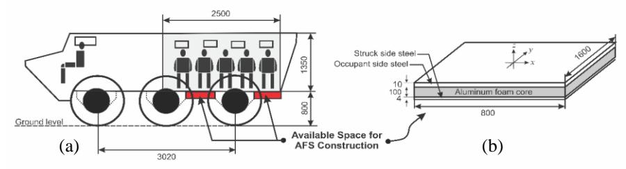
Figure 1 The geometrical consideration; (a) available space under the armored vehicle floor and (b) aluminum foam sandwich specimen.
Figure 2 (a) shows four groups of components based on their function; AFS as specimen, blast load source as the origin of the free air-burst pressure, jig and fixture as holder, and data acquisition system as data acquirer. The accelerometer is installed on the central node of the occupant side steel and the load cell is installed on the leg support.
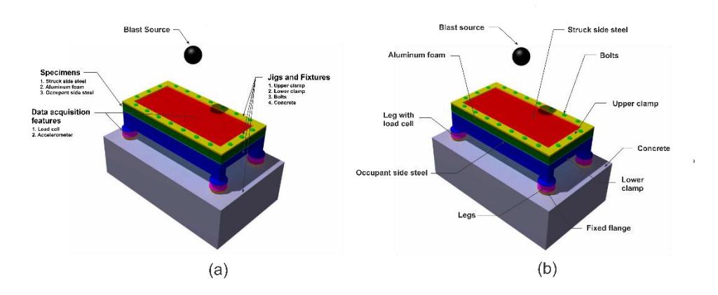
Figure 2 Components of blast experiment setup; (a) four components set based on the function and (b) the detail components.
Figure 2 (b) shows the detail components of the blast experimental setup. Beside aluminum foam sandwich, there are bolts, upper clamp, bottom clamp, legs, leg with load cell, fixed flange, and concrete. The specification for these components are (1) aluminum foam with density of 0.8 g/cm3 , (2) blast load source of 8 kg TNT with stand-off distance of 800 mm from occupant side steel, (3) struck side steel with medium strength steel CR420 with thickness of 4 mm, (4) one inch structural bolts, (5) upper clamp with material of structural steel with thickness 20 mm and width 100 mm, (6) concrete to stiffen the fixture, (7) bottom clamp with material of structural steel, (8) fixed flange which is embedded inside the concrete, (9) three legs with material of mild steel, (10) occupant side steel with material of ultra-high strength steel 1100T with thickness 10 mm and also accelerometer will be installed in the central node, and (11) one leg as load cell. Figure 3 shows the dimension of aluminum foam sandwich specimen that installed on the blast experimental setup.
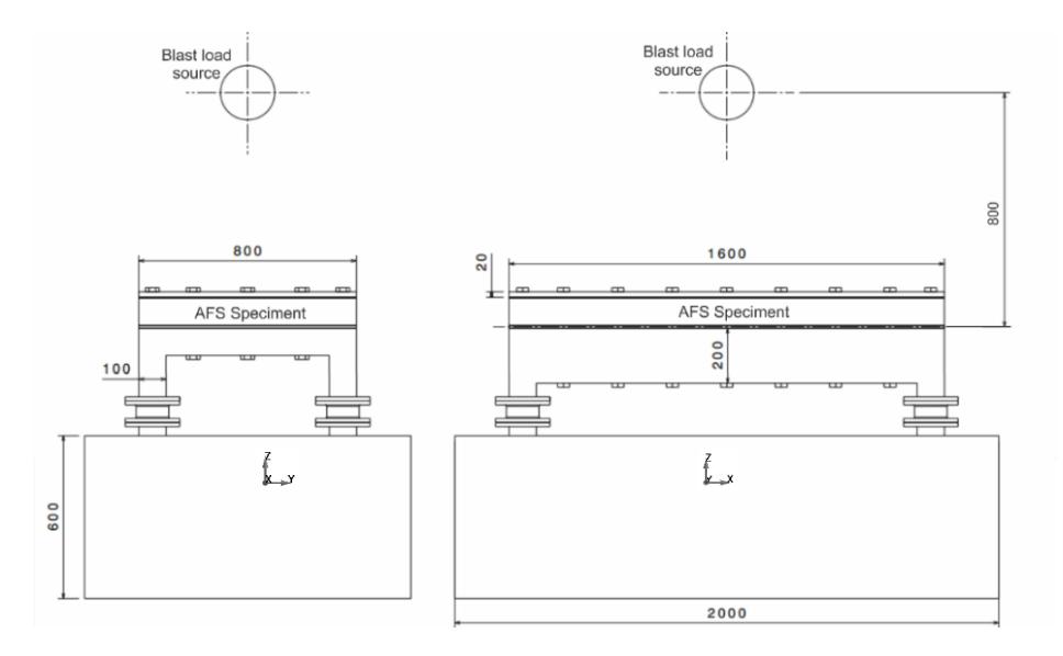
Figure 3 Drawing of aluminum foam sandwich specimen that installed on the blast experiment setup.
3 Numerical analysis
3.1 Boundary condition, load definition and contact definition
The dynamic-explicit finite element analysis solver of LS-DYNA is used to simulate finite element model of the blast experiment setup. Figure 4 shows the fixed support boundary condition using single point constraint (SPC) for all direction on the legs. For blast loading modeling, LOAD_BLAST_ENHANCED keyword to model 8 kg TNT as an air blast pressure loads of conventional weapons (CONWEP) is used which has a good agreement with experimental data [7, 13, 14]. The blast pressure is applied to the upper surface of struck side steel (SSS) and the upper surface of upper clamp. The oscillation of the system was damped by mass weighted damping [15],
\[F_{damp} = D_s mv (1)\] where m is system mass, v is system velocity, and Ds is damping constant. The best damping constant is the critical damping constant,
\[D_s = 2\omega_n \tag{2}\] where is first natural frequency. The first natural frequency is obtained by using implicit analysis to obtain eigenvalue of the system using CONTROL_IMPLICIT_EIGENVALUE in LS-DYNA. The first natural frequency of the system is 190 rad/s so that the damping constant equal to 380 rad/s.
Figure 4 Boundary and loading condition of aluminum foam sandwich specimen and blast experiment setup.
The used contacts are node to surface, surface to surface, and surface to surface tiebreak contact model. CONTACT_AUTOMATIC_NODES_ TO_SURFACE is defined for contacts between solid surfaces and shell edges such as on bolts (solid element) and upper clamp, bottom clamp, occupant side steel (OSS), and struck side steel (SSS) (shell element). CONTACT_AUTOMATIC_SURFACE _TO_SURFACE is defined for contacts between two surfaces (shell or solid element) such as on SSP or OSP and aluminum foam, OSP and lower clamp, and upper clamp and SSP. CONTACT_AUTOMATIC_SURFACE_TO_SURFACE _TIEBREAK is used to define permanently stick between legs and lower clamp, and tiebreak contact between OSS or SSS and aluminum foam that has normal and shear failure stresses of 150 MPa
3.2 Material modelling
The material modeling for each part can be seen in Figure 5. It is classified into three main parts of struck side and occupant side steel, aluminum foam, and structural steel.
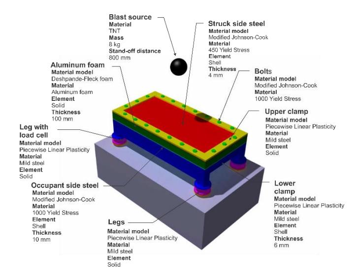
Figure 5 Material model for all components.
3.2.1 Struck side and occupant side steel
The struck side steel and occupant side steel is modeled by using modified Johnson-Cook (MAT_MODIFIED_JOHNSON_COOK (107)) as fully integrated shell element (very fast) with mesh size of 10 mm. This material model calculates strain rate effects (increasing the strength), failure criteria, thermal effects (decreasing the strength), and damage effects [16]. The true plastic stress-strain curve was governed by Johnson-Cook formula [17],
\[\sigma_{pl} = \left(A + B\varepsilon_{pl}^{n}\right) \left(1 + \frac{\dot{\varepsilon}}{\dot{\varepsilon}_{0}}\right)^{c} \left(1 - \left(\frac{T - T_{r}}{T_{m} - T_{r}}\right)^{m}\right) \tag{3}\] where A is yield strength, B is strain hardening coefficient, C is strain rate sensitivity factor, and m is temperature effect coefficient. Technically, these parameters were obtained from curve fitting on the tensile test result in various strain-rates. The modified Johnson-Cook parameters are summarized in where is critical failure strain, is true stress, and is true strain of material
Table 1 and demonstrated in various strain rate and temperature in Figure 6 and Figure 7. The fracture criteria of these material follows equation of critical work by Cockcroft-Latham [18],
\[W_c = \int_0^{\varepsilon_C} \sigma \ d\varepsilon \tag{4}\]
where is critical failure strain, is true stress, and is true strain of material
| Material | CR420 | 1100T | |
|---|---|---|---|
| E (GPa) | 222 | 222 | |
| Elastic constants and density | 𝜐 | 0.3 | 0.3 |
| 𝜌 (kg/m3 ) | 7830 | 7830 | |
| A (MPa) | 450 | 1000 | |
| Yield stress and strain hardening | B (MPa) | 446 | 490 |
| n | 0.743 | 0.26 | |
| ̇ (s-1 ) 𝜀0 | 0.001 | 0.001 | |
| Strain rate hardening | C | 0.015 | 0.001 |
| Tr (K) | 295 | 295 | |
| Tm (K) | 1370 | 1370 | |
| Temperature softening and adiabatic heating | m | 1.03 | 1.03 |
| Cp (J/kg K) | 500 | 500 | |
| 𝜒 | 0.9 | 0.9 | |
| 𝛼 (K-1 ) | 1.5x10⁻⁵ | 1.5x10⁻⁵ | |
| Failure criteria | WC (MPa) | 174 | 193 |
Table 1 Modified Johnson-Cook material parameters.
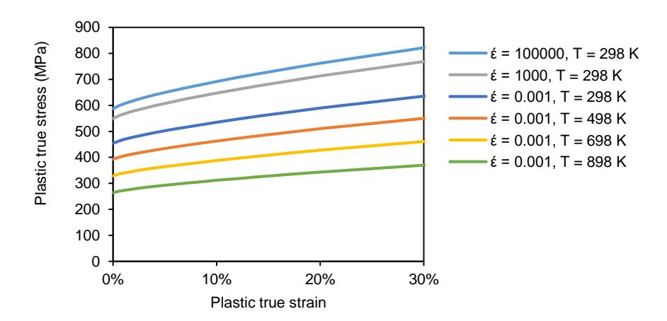
Figure 6 Modified Johnson-Cook material model for CR420 in various strain rate and temperature.
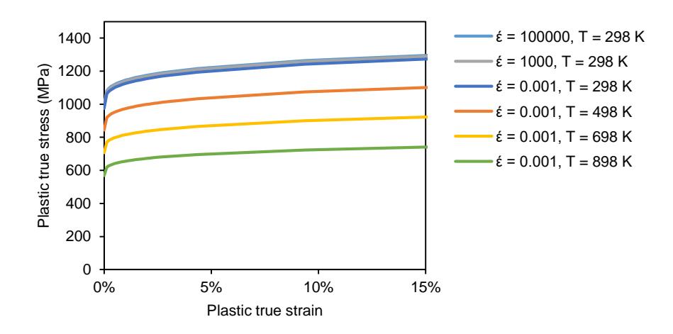
Figure 7 Modified Johnson-Cook material model for 1100T in various strain rate and temperature.
3.2.2 Aluminum foam
Material constitutive model for aluminum foam is done by Deshpande-Fleck foam [19]. According to LS-DYNA, MAT_DESHPANDE_FLECK (154) was proper to model metallic foam include that includes failure criteria by stating facture strain [16]. The procedure of Hanssen et al. [20] was adopted to calculate the Deshpande-Fleck foam parameters. The yield stress is governed by following equation,
\[\sigma_{Y} = \sigma_{p} + \gamma \frac{\hat{\varepsilon}}{\varepsilon_{D}} + \alpha_{2} \ln \left( \frac{1}{1 - (\hat{\varepsilon}/\varepsilon_{D})^{\beta}} \right)\] (5)
where \(\sigma_p\) is plateau stress, \(\hat{\varepsilon}\) is engineering strain, \(\varepsilon_D\) is densification strain, and \(\alpha_2\), \(\gamma\), and \(\beta\) are hardening parameters. These parameters are calculated by following equations,
\[\left\{\sigma_{p},\alpha_{2},\gamma,\frac{1}{\beta},E\right\} = C_{0} + C_{1} \left(\frac{\rho_{f}}{\rho_{s}}\right)^{n} \tag{6}\]
\[\varepsilon_D = -\ln\left(\frac{\rho_f}{\rho_s}\right) \tag{7}\]
\[\alpha^2 = \frac{9(1 - 2v_p)}{2(1 + v_p)} \tag{8}\] where \(\rho_f\) is foam density, \(\rho_s\) is the solid material density, E is Young's modulus, and \(v_p\) is Poisson's ratio. The parameters \(C_0\), \(C_1\), and n are according to the data from Hanssen et al. [20] that shown Table 2.
Table 2 Material parameters of aluminum foam constitutive model. [20]
| Parameters | \(\sigma_p\) (MPa) | α2 (MPa) | 1/β | γ (MPa) | E (MPa) |
|---|---|---|---|---|---|
| \(C_0\) | 0 | 0 | 0.22 | 0 | 0 |
| \(C_1\) | 590 | 140 | 320 | 40 | \(3.3 \times 10^{5}\) |
| n | 2.21 | 0.45 | 4.66 | 1.4 | 2.45 |
By substituting Table 2 to the equation (6), (7) and (8), the Deshpande-Fleck foam parameters was obtained as listed in Table 3 and visualized by Figure 8.
Table 3 Deshpande-Fleck foam parameters of aluminum foam with a density of 0.8 g/cm<sup>3</sup>.
| Density, \(\rho\) (g/cm3) | 0.8 |
| Young's modulus, E (MPa) | 16.8 |
| Plateau stress, \(\sigma_p\) (MPa) | 40.12 |
| Poisson ratio, \(\nu_p\) | 0 |
| γ (MPa) | 7.28 |
| Densification strain, \(\varepsilon_D\) | 1.21 |
| α | 2.12 |
| β | 0.75 |
| \(\alpha_2\) (MPa) | 80.98 |
| Failure strain | 0.58 |
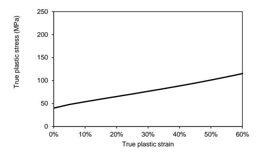
Figure 8 Compression plastic stress-strain curve from Deshpande-Fleck foam material model.
3.2.3 Structural steel
Material of the legs, bolts, upper clamp, and bottom clamp is structural steel St37. This material was characterized by A. Jusuf et al. [21] where the mechanical properties of St37; Young's modulus is 188 GPa, the density is 7330 kg/m3 , Poisson's ratio is 0.3, the yield stress is 186.95 MPa, the tensile test is 289.56 MPa, and the Cowper-Symonds constants are C = 40.4 and P = 5 [22]. This material is modeled with MAT_PIECEWISE_LINEAR_PLASTICITY (24) and the parameters are summarized on Table 4.
Table 4 Piecewise linear plasticity parameters of structural steel. [21]
| 𝜌 | E | 𝜐 | 𝜎𝑌 | 𝜎𝑈 | C | P |
|---|---|---|---|---|---|---|
| (kg/m3 ) | (GPa) | (MPa) | (MPa) | |||
| 7330 | 188 | 0.3 | 186.95 | 289.56 | 40.4 | 5 |
4 Results and discussion
4.1 Load cell design
In LS-DYNA, reaction forces on the load cell were calculated by extracting resultant interface force on contact between legs and lower clamp. Figure 9 shows reaction force for one leg. The force-time history explains compression on the load cell at 0 – 4.5 ms with peak force 631 kN and tension in load cell at 4.5 - 9 ms with peak force about 264 kN. This value depends on the strength of legs, bolts, upper clamp, and bottom clamp. The stronger the material, the higher the peak force to deform the components.
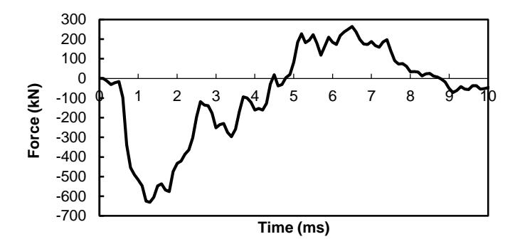
Figure 9 Numerical prediction for reaction force in the load cell.
The alternative sensors on generating voltage – force correlation for forces measurement through the load cell are strain gauge and piezoelectric. In the piezoelectric load cell, the cross-section area has been considered by the producer that depends on the desire load capacity. The piezoelectric load cell to measure compression force up to 631 kN is 700 kN that available on market (load washer 9107A Kistler®). For the strain gauge load cell design, the crosssection area is must be designed by defining maximum compression force as a constraint. The strain gauge is installed on a solid geometry that must sustain this maximum force so that the plastic deformation can be avoided. The installed strain gauge location must remain in the elastic deformation of the material so that the voltage – force linear correlation can be maintained. In current study, strain gauge is installed on the leg (solid cylinder with upper and lower flange) made by mild steel St37 so that the cross-sectional area of the load cell can be calculated by equation,
\[A = \frac{F_r}{0.4\sigma_y} = \frac{953 \text{ kN}}{0.4(250000 \text{ kN/m}^2)} \approx 0.01 \text{ m}^2\] (7)
where is the maximum compression force, is yield stress of St37, and 0.4 is linearity area below yield stress (40% of yield stress). By using solid cylindrical geometry, the cross-section radius is = √/ = √0.01/ = 0.0564 m = 56.4 mm, rounded to 60 mm. Figure 10 (a) & (b) show corresponding load cell geometry and its dimension. Figure 10 (c) & (d) show strain gauge position on the middle of cylinder that only receive pure/average compression load. For manufacturing, the machining process is recommended as early research on load cell design by L. Gunawan et al. [23]. The welding joint between flanges and the cylinder is not recommended that gives inaccurate result. This is due to the force distribution not uniform, only distributed through the welding.
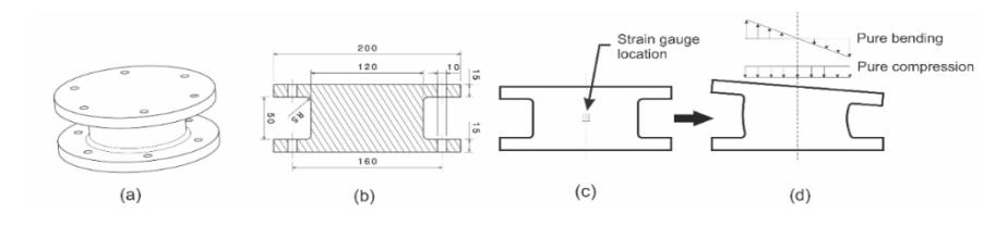
Figure 10 Load cell design; (a) overall design of the load cell, (b) cylinder and flanges dimension, (c) strain gauge position, and (d) load condition in load cell structure.
Figure 11 shows the effective stress and effective plastic strain that observed at the cylinder on a leg for strain gauge installation. The maximum effective stress is 39.16 MPa which is much lower than the yield stress 186.95 MPa so that there is no plastic deformation on the cylinder (Figure 11). The maximum effective plastic strain is very small \((3.708 \times 10^{-5})\) that occurs on the upper cylinder.
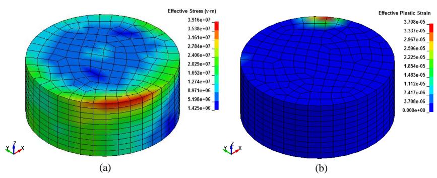
Figure 11 (a) The effective stress and (b) the effective plastic strain in the load cell at 11 ms.
In the strain gauge location (Figure 12), the stress and strain - time history on z direction over time indicate no plastic deformation because of stresses still below the yield stress. Therefore, this load cell design is appropriate for force measurement using strain gauge sensor.
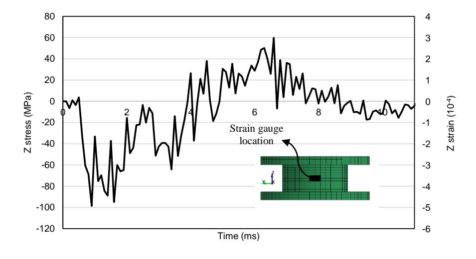
Figure 12 History of (a) z stress and (b) z strain in the strain gauge location.
4.2 Accelerometer design
Acceleration data in the central node of occupant side steel (OSS) was acquired by using nodal history of displacement that shown in Figure 13 (a). Then, the double differentiates of this curve equal to acceleration-time history Figure 13 (b)). Figure 13 (a) demonstrates deflection of the OSS's center point to z (-) direction at 0-3 ms which caused by the blast pressure on the same direction then the deflection moves to z (+) direction from 3-6 ms which indicates
bouncing effect that also occurred on the experiment by Boyd [24]. In the steady state condition, 10 mm permanent displacement is occurred after simulation (11 ms).
Figure 13 (b) describes OSS's center point acceleration oscillation with minimum and maximum amplitudes are -16114~G and 14052~G respectively. Then, the oscillation is damped until 7 ms by using mass weighted damping. For the worse case condition, high acceleration due to concentrated blast loading is anticipated by increasing the accelerometer range become 50000 G. The available accelerometer for this capacity is 350D02~(PCB@) that has maximum and minimum acceleration up to \(\pm 50.000~G\).
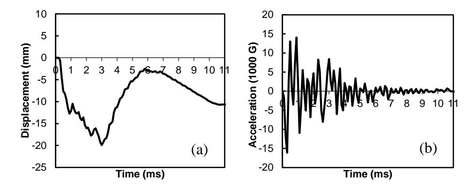
Figure 13 The dynamic of OSS's center point; (a) displacement and (b) acceleration.
Figure 14 shows the design of accelerometer mounting that is welded to the center of occupant side steel. The mounting material is mild steel where the thickness and diameter are 4 mm and 100 mm respectively. The appropriate thread is created to install accelerometer in the center.
Figure 14 Design of accelerometer and its mounting.
5 Conclusion
Numerical study of experimental setup to evaluate aluminum foam sandwich construction undergoing blast loading was successfully conducted. Two blastworthiness parameters in form of force and acceleration are introduced to evaluate aluminum foam sandwich specimen. Design of data acquisition systems for force and acceleration measurement is undertaken by using load cell and accelerometer. Analysis on the load cell and accelerometer gives the maximum compression load for one leg up to 631 kN. The available load cell for this capacity is 9107A (Kistler) that has maximum compression load 700 kN. For accelerometer, the maximum acceleration is 16114 G. The available accelerometer for this capacity is 350D02 (PCB) that has maximum and minimum acceleration up to ±50.000 G.
6 Acknowledgment
We acknowledge to Indonesian Ministry of Finance (LPDP) who provided research grants. We also thank to Indonesian Ministry of Research Technology and Higher Education, under the scheme of PMDSU (Master to Doctor for Superior Student Program). We also grateful to LSTC for LS-DYNA license to Lightweight Structure Laboratory ITB.
7 References
- [1] R. Panowicz, K. Sybilski and D. Kolodziejczyk, "Numerical Analysis of Effects of IED Side Explosion on Crew of Lightarmoured Wheeled Vehicle," Journal of KONES Powertrain and Transport, vol. 18 No.4, p. 332, 2011.
- [2] A.G. Hanssen, O.S. Hopperstad, M. Langseth, H. Ilstad, "Validation of constitutive models applicable to aluminium foams," International Journal of Mechanical Sciences, vol. 44, no. Elsevier, pp. 359-406, 2002.
- [3] S. P. Santosa, T. Wierzbicki, A. G. Hanssen and M. Langseth, "Experimental and numerical studies of foam-filled sections," International Journal of Impact Engineering, vol. 24, pp. 509-534, 2000.
- [4] B. A. Gama, et.al, "Aluminum foam integral armor : a new dimension in armor design," Composite Structures, vol. 52, 2001.
- [5] A.G. Hanssen, L. Enstock, M. Langseth, "Close range aluminum foam sandwich subjected to blast load," International Journal of Impact Engineering, vol. 27, no. Elsevier, pp. 593-618, 2002.
- [6] M.D. Theobald , G.S. Langdon, G.N. Nurick, S. Pillay, A. Heyns, R.P. Merrett, "Large inelastic reponse of unbonded metallic foam and honeycomb core sandwich panels to blast loading," Composite Structures, vol. 92, no. Elsevier, pp. 2465-2475, 2010.
- [7] J. Park and H. J. Choi, "Experiments and numerical analyses of HB400 and aluminum foam sandwich structure under landmine explosion," Composite Structures, vol. 134, p. 726–739, 2015.
- [8] D.D. Radford, G.J. McShane, V.S. Deshpande, N.A. Fleck, "The response of clamped sandwich plates with metallic foam cores to simulated blast loading," International Journal of Solids and Structures, vol. 43, no. Elsevier, pp. 2243- 2259, 2005.
- [9] Lin Jing, Zhihua Wang, V.P.W. Shim, Longmao Zhao, "An experimental study of the dynamic response of cylindrical sandwich shells with metallic foam cores
- subjected to blast loading," International Journal of Impact Engineering, vol. 71, no. Elsevier, pp. 60-72, 2014.
- [10] H. Liu, Z. K. Cao, G. C. Yao, H. J. Luo, and G. Y. Zu, "Performance of aluminum foam steel panel sandwich composites subjected to blast loading," Materials and Design, 2013.
- [11] Feng Zhu, Longmao Zhao, Guoxing Lu, Zhihua Wang, "Deformation and failure of blast-loaded metallic sandwich panels - experimental investigation," International Journal of Impact Engineering, vol. 35, no. Elsevier, p. 937–951, 2008.
- [12] Feng Zhu, Longmao Zhao, Guoxing Lu, Zhihua Wang, "Structural response and energy absorption of Sandwich Panels with an Aluminium Foam Core Under Blast Loading," Advances in Structural Engineering, vol. 11, pp. 525-536, 2008.
- [13] A. Furqan, S. P. Santosa, A. S. Putra, D. Widagdo, L. Gunawan and F. Arifurrahman, "Blast Impact Analysis of Stiffened and Curved Panel Structures," in 11th International Symposium on Plasticity and Impact Mechanics, New Delhi, 2016.
- [14] S. P. Santosa, F. Arifurrahman, M. H. Izzudin, D. Widagdo and L. Gunawan, "Response Analysis of Blast Impact Loading of Metal-Foam Sandwich Panels," Procedia Engineering, IMPAST 2016, vol. 173, no. Elsevier, pp. 495-502, 2017.
- [15] J. Hallquist, "LS-DYNA Theory Manual," LSTC, Michigan, 2006.
- [16] LSTC, "LS-DYNA keyword user's manual volume II: Material Models, Version 971," Livermore Software Technology Corporation, Michigan, 1999.
- [17] Johnson, G.R., Cook, W.H., "A constitutive model and data for metals subjected to large strains, high strain rates and high temperatures," in Proceedings of the 7th International Symposium on Ballistics, The Hague, The Netherlands, 1983.
- [18] M. G. Cockcroft and D. J. Latham, "Ductility and the workability of Metals," Journal of the Institute of Metals, vol. 96, pp. 33-39, 1968.
- [19] V. S. Deshpande and N. A. Fleck, "Isotropic constitutive models for metallic foams," Journal of the Mechanics and Physics of Solids, vol. 48, no. 6, pp. 1253- 1283, 2000.
- [20] A. Reyes , O.S. Hopperstad, T. Berstad, A.G. Hanssen, M. Langseth, "Constitutive modeling of aluminum foam including fracture and statistical variation of density," European Journal of Mechanics A/Solids, vol. 22 , p. 815– 835, 2003.
- [21] Annisa Jusuf, Tatacipta Dirgantara, Leonardo Gunawan, Ichsan Setya Putra, "Crashworthiness Analysis of Multi-Cell Prismatic Structures," International Journal of Impact Engineering , vol. 78, pp. 34-50, 2015.
- [22] N. Jones, Structural Impact 2nd Edition, Cambridge: Cambridge University Press, 2012.
- [23] L. Gunawan, T. Dirgantara and I. S. Putra, "Development of a Dropped Weight Impact Testing Machine," Journal of Engineering & Technology, IJET: International, vol. 11, no. 06, 2011.
- [24] S. D. Boyd, "Acceleration of a Plate Subject to Explosive Blast Loading Trial Results," 2000.