
1. Introduction
1.1 Background
Wood is extensively used for construction especially in rural area where timber can be quite easy to get. Wood is used in truss structures such as roof and bridge besides frame and floor system. Some advantages that would be obtained when wood is used in construction compared with the other materials are: first is the total weight of construction would be smaller, and second is the simplicity in fabrication.
As a natural resources, wood differs in many ways. Two kinds of wood that will be used in this research are Bangkirai and Coconut. According to Awaludin & Triwiyono (2002), and Morisco (1998), the strength of Bangkirai lumber is higher than that of Coconut lumber, so that for structural construction people only use Bangkirai. However, since not all elements of structural construction sustain equal load, the strength grade of lumber in a structural construction can be varied. This combination lumbers in a construction is called composite structure. In composite structure,
Catatan : Usulan makalah dikirimkan pada 16 April 2003 dan dinilai oleh peer reviewer pada tanggal 7 Mei 2003 – 19 Mei 2003. Revisi penulisan dilakukan antara tanggal 2 Juni 2003 hingga 16 Juni 2003.
1) Lecturer at Civil Engineering Department of Gadjah Mada University
woods of high grade, middle grade, and low grade can be used optimally and wisely to conserve wood sustainability.
Bolt has been used in wood joint or connection since long time ago. Bolt is one of the mechanical connector where the connection strength is determined by the bending strength of bolt and the bearing or shear stress of wood. Joint in wood structure is known as the weakest part. The increase in connection strength will give significant benefit to whole structure. Many research have done to find out wood jointing methods and wood connectors.
In the previous research, Awaludin & Triwiyono (2002), three-member connection of Coconut and Bangkirai lumber were tested in several angles of load to grain. Two bolts of 15.6 mm (5/8 inchi) were used as the connectors. Because the need to increase the tensile load and to decrease the displacement, split ring will be used in this experiment. In addition to that, the ultimate tensile load of connection of experiment also will be evaluated with some theoretical formulae.
2. Objectives
The objectives of this research were:
- 1. to find out the load-slip curve of three-member connection of Coconut and Bangkirai lumber with split ring connector,
- 2. to find out the advantage of using split ring connectors compared with bolt connector in threemember connection of Coconut and Bangkirai lumber, and
- 3. to evaluate the ultimate tensile load of split ring connection with some theoretical formula.
3. Literature Cited
Because wood is a natural resource, the structural properties of wood vary from one species to another species and even in one trunk: the bottom, the middle, and the upper part. Two things that are potentially controlled the strength of wood are moisture content and density or specific gravity. Water exists in wood in two ways: in the cell cavities as free water and in the cell wall as bound water. There are three common conditions in describing water content in wood: green water, fiber saturation point, and air-dry condition. For structural purposes, it is recommended to use lumber at air-dry condition (the water content is about 12 to 15%). The strength of wood increases as the water content decreases. But the water content decrease should be made gradually to avoid crack or split. Density can be used to predict the strength of a specific wood. Wood with high density will also have high strength grade.
Ring (split ring) is used laterally loaded timber to timber connection and generally in combination with bolt (see Figure 1). Ring is available in a variety of shape and size. The common shape of ring are double bevel and flat, and the common size are 2½ inchi (64 mm) and 4 inchi (100 mm). Diameter of bolt which is used in 2½ inchi and 4 inchi ring are ½ inchi and ¾ inchi respectively. This bolt is used to tight the connection so that the ring connector worked optimally. According to Blass in Blass et al (1995), rings are always circular because they are placed into precut grooves produced by rotary cutters and are made from aluminum cast alloy, steel or cast iron.
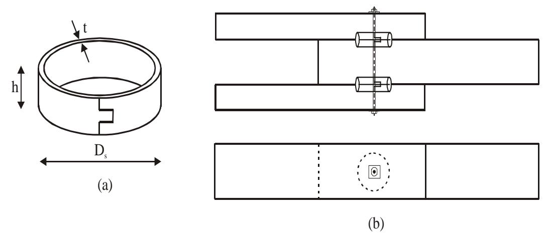
Figure 1. Flat split-ring (a) and split-ring connection (b)
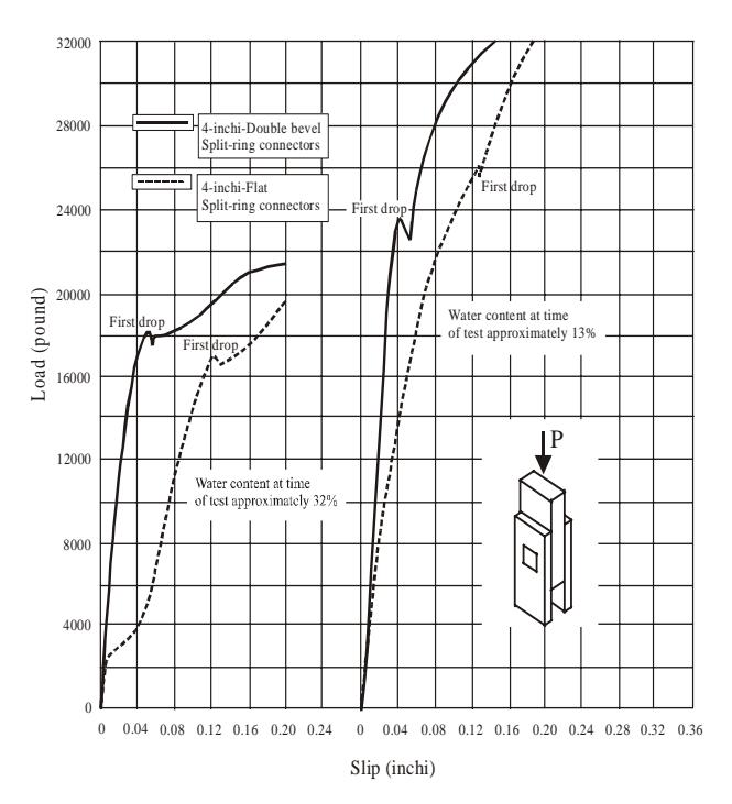
Figure 2. Load-slip curve of 4 inchi split-ring connections at 13% and 32% water content
The tensile load of split ring connection is determined not only by the diameter and the length of ring, but also the water content of members as shown in Figure 2. Tensile load of double bevel ring is higher than that of the flat ring, while the displacement of double bevel ring is smaller than that of flat ring. The failure mode of ring connection can be studied in Figure 2. According to Faherty (in ASCE, 1996), at the proportional limit, wood between the ring and bolt begin to crush, then followed by the bent of bolt. After that, the final failure of wood splitting parallel to grain occurs until its ultimate tensile load. Beyond the proportional limit, depending on the thickness of the members, wood splitting may occur rather abruptly (in thin member) or additional compression of wood fiber takes place and the bolt begins to bend (thick member).
Euro Code 5 in Blass et al (1995) introduce Equation 1 and Equation 2 to analyze the tensile load of split ring connection \((P_{sr})\). The least value of these two equation is used as the design value. The tensile load which is sustained by the bolt is neglected. These equations give good prediction at 13% of water content. Equation 3 is used to obtained tensile load of split ring connection when the load direction to grain is not parallel.
\[P_{sr} = 20 A_s^{0.75} (1)\]
\[P_{sr} = 0.09. \rho. D_{s}. h \tag{2}\]
\[P_{sr\theta} = \frac{P_{sr//}}{k \sin^2 \theta + \cos^2 \theta} \tag{3}\] where, \[k = 1.3 + 0.001D_s\] and \(A_s = (D_s + h)a - \frac{\pi D_s^2}{8}\)
According to Awaludin & Triwiyono (2002), the ultimate tensile load of split ring connection is the total tensile load that is developed by the ring and the bolt. The tensile load that is developed by the ring is a combination between shear and compression strength. Equation 4 is recommended formula by Awaludin & Triwiyono (2002) to obtain the ultimate tensile load of split ring connection. Tensile load which is developed by bolt (P<sub>b</sub>) is similar to the nominal strength of bolt
\[P_{sr} = P_b + \lambda_s P_s + \lambda_c P_c \tag{4}\]
\[P_{s//} = m \frac{\pi D_s^2}{2} \tau_{//} (1 - 0.6 \sin \theta)\] (5)
\[P_{e//} = m \frac{\pi D_s h}{2} F_{e//} (1 - 0.6 \sin \theta)\] (6)
The nominal
strength for one bolt (Z) of three-member connection is the least value which is obtained from Equation 5 to Equation 8 in Table 1. Yield mode in Table 1 describes the failure mode of bolted connection. The yield modes I<sub>s</sub> and I<sub>m</sub> are the result of wood fiber crushing in side member and main member respectively. Yield mode IIIs is the result of bolt yielding with one plastic hinge at the shear plane along with the wood fiber crushing in side member. Yield mode IV is the result of bolt yielding in many plastic hinges.
Table 1. Connection yield load of three-member bolted connection
| Connection yield modes | Nominal strength for one bolt (Z) | ||
|---|---|---|---|
| \(I_s\) | \[Z = \frac{1.66Dt_s F_{es}}{K_{\theta}}\] | (7) | |
| \(I_{m}\) | \[Z = \frac{0.83Dt_{m}F_{em}}{K_{\theta}}\] | (8) | |
| \(\mathrm{III}_{\mathrm{s}}\) | \[Z = \frac{2.08k_3Dt_sF_{em}}{(2+R_e)K_\theta}\] | (9) | |
| IV | \[Z = \frac{2.08D^{2}}{K_{\theta}} \sqrt{\frac{2F_{em}F_{yb}}{3(1+R_{e})}}\] | (10) | |
\[k_{3} = -1 + \sqrt{\frac{2(1 + R_{e})}{R_{e}} + \frac{2F_{yb}(2 + R_{e})D^{2}}{3F_{em}t_{s}^{2}}}\] \[R_{e} = \frac{F_{em}}{F_{es}}\] \[K_{\theta} = 1 + \frac{\theta}{360}\]
4. Material
Twelve three-member connections of Coconut and Bangkirai lumber were made in this research. The side members of connection were two Coconut lumber of 40/150 mm<sup>2</sup>, and the main member was one Bangkirai lumber of 60/150 mm<sup>2</sup>. The angle of load to grain is varied into 90°, 60°, 45°, and 0° (parallel) to side members. Two split rings of 40 mm in diameter, 30 mm in length and two bolts of 12.5 mm (1/2 inchi) in diameter were used in every connection.
Preliminary tests such as water content test, dowel bearing strength, and mechanical properties of Coconut and Bangkirai lumber were conducted. Drying process is also conducted to obtained air-dry lumber. The connection specimens were tested until its ultimate tensile load. Failure mode and displacement were also observed to obtain load-slip curve of connection.
5. Result and Discussion
Three-member connections were assembled and tested in air-dry condition. The water content at time of test of Coconut and Bangkirai lumber were 15.86% and 17.95% respectively. The result of tensile test which is presented in load-slip curve showed that: The load-slip curve of split-ring connection is steeper than that of bolted connection, and the ultimate tensile load of split ring connection was higher than that of bolted connection especially when the angles of load to grain were 45° and 60°. The average ratio between the ultimate tensile load of split ring connection to the ultimate tensile load of bolted connection \((P_{sr}/P_b)\) was 1.30 as shown in Table 2. Furthermore, the displacement of split ring connection was smaller than the displacement of bolted connection. For instance, when the tensile load was parallel to grain, the displacement of split ring connection was only 67% of the displacement of bolted connection. The yield mode of connection was initiated by the crush of wood between ring and bolt, followed by the bent of bolt until the ultimate tensile load. The deformation on ring connectors was observed after the connections were dismantled. There is no significant deformation on ring connectors. But all ring connectors and bolts became so rusty around the Coconut lumber (side members).
The ultimate tensile load of split ring connection can be evaluated with Equation 1 to Equation 3 of Euro Code 5 and Equation 4 to Equation 6 of Awaludin & Triwiyono (2002). Data from experiment which were used to evaluate the ultimate tensile load of connection were listed below. Density (ρ) of Coconut lumber was taken from Morisco et al (1998). Bending strength of bolt was taken 320 N/mm<sup>2</sup> as it is suggested by National Design and Specification (NDS) of USA for timber construction (ASCE, 1996). The ultimate tensile load of split ring connection which was evaluated with Euro Code 5 was presented in Table 4.
Table 2. Ultimate tensile load of connection
| Angle of connection (\theta) | Bolted connection (Pb) (kg) | Split-ring connection (Psr) (kg) | \(P_{sr}/P_b\) | |
|---|---|---|---|---|
| 0° | 45783 | 50688 | 1.11 | |
| 45° | 28096 | 39446 | 1.40 | |
| 60° | 23672 | 34698 | 1.46 | |
| 90° | 24133 | 29224 | 1.21 | |
| Average | 1.30 | |||
Table 3. Maximum slip of connection with tensile loaded parallel to grain
| Bolted connection \((\delta_b)\) (mm) | Split ring connection \((\delta_{sr})\) (mm) | \(\delta_{ \scriptscriptstyle Sr} /\delta_{ \scriptscriptstyle b}\) |
|---|---|---|
| 40.78 | 31.45 | 0.77 |
| 22.35 | 15.25 | 0.68 |
| 22.60 | 12.75 | 0.56 |
| Ave | rage | 0.67 |
\[\rho = 0.0065 \text{ N/m}^3\] \(D = 12.5 \text{ mm}\) \(D_s = 40 \text{ mm}\) \(m = 2\) \(h = 30 \text{ mm}\) \(a = 147 \text{ mm}\) \(t_s = 40 \text{ mm}\) \(t_m = 60 \text{ mm}\) \(F_{es} = 14.25 \text{ N/mm}^2\) \(F_{em} = 58.69 \text{ N/mm}^2\) \(F_{yb} = 320 \text{ N/mm}^2\) \(\tau_{l/} = 2.32 \text{ N/mm}^2\)
Table 4. Ultimate tensile load connection according to Euro Code 5
| Angle of connection (\theta) | Equation 1 (N) | Equation 2 (N) | Ultimate tensile load (N) |
|---|---|---|---|
| 0° | 38982 | 70200 | 38982 |
| 45° | 33322 | 60007 | 33322 |
| 60° | 31065 | 55943 | 31065 |
| 90° | 29091 | 52388 | 29091 |
The failure mode of split ring connection was a combination between the strength of bolt, the shear strength and dowel bearing strength of wood around the ring. Since the shear strength of Coconut lumber was lower than its dowel bearing strength, so the strength reduction factor \((\lambda_s)\) will be equal to one and the compressive strength reduction factor (\(\lambda_c\)) will lay between nil to one. Some modification was made to Equation 5 and Equation 6. This modification was written in Equation 11 to Equation 14. The ultimate tensile load of split ring connection was obtained from Equation 4 and step by step described in Table 5. The compressive reduction factors of 0, 0.5, and 1.0 were applied to analyze the ultimate tensile load, while the shear strength reduction factor was 1.0.
\[P_{s//} = m \frac{\pi D_s^2}{2} \tau_{//} \tag{11}\]
\[P_{s\theta} = \frac{0.4 P_{s//}^{2}}{P_{s//}(\sin^{2}\theta + 0.4\cos^{2}\theta)}\](12)
\[P_{e//} = m \frac{\pi D_s h}{2} F_e \tag{13}\]
\[P_{c\theta} = \frac{0.4 P_{c//}^{2}}{P_{c//}(\sin^{2}\theta + 0.4\cos^{2}\theta)}\](14)
The ultimate tensile load of Awaludin & Triwiyono (2002) with \(\lambda_c\)=0.5, of experiment, and of Euro Code 5 were plotted in Figure 3. It can be seen in Figure 3 that the ultimate tensile load of experiment were scattered closely to both Euro Code 5 and Awaludin & Triwiyono (2002) curves, except for one data of 45° of connection angle. The ultimate tensile load curve of Euro Code 5 intersects with the curve of Awaludin & Triwiyono (2002) in connection angle from 45° to 60°. The ultimate tensile load of Euro Code 5 at connection angle below 45° was lower than that of Awaludin & Triwiyono (2002). While at connection angle from 60° to 90°, the ultimate tensile load of Euro Code 5 was higher than that of Awaludin & Triwoyono (2002). For analysis, equation of Euro Code 5 can be used instead of that of Awaludin & Triwiyono (2002).
Two questions arise in the equation which was suggested by Awaludin & Triwoyono (2002) are: (1). the value of compressive reduction factor \((\lambda_c)\) will be equal to 0.5 or will be not if the size of split-ring changes, and (2). If the diameter of bolt higher than 12.5 mm, will the ultimate tensile strength of connection increases?. To answer these questions, future research on split ring connection which various value of diameter, length of split ring connector, and diameter of bolt should be conducted.
Table 5. Ultimate tensile load connection according to Awaludin & Triwiyono (2002)
| Angle of connection | Load contribution from 2 bolts (N) | Load contribution from 2 split rings (N) | Ultimate tensile load \((P_{sr})\) (N) | ||||
|---|---|---|---|---|---|---|---|
| \((\theta)\) | \((P_b)\) | Yield mode | \((P_s)\) | \((P_c)\) | \(\lambda_{\rm c}=0.0\) | \(\lambda_{\rm c}=0.5\) | \(\lambda_{\rm c}=1.0\) |
| 0° | 15021 | \(I_{\rm s}\) | 11656 | 52677 | 26677 | 53015 | 79353 |
| 45° | 13352 | \(I_{\rm s}\) | 6663 | 30111 | 20015 | 35070 | 50126 |
| 60° | 12875 | \(I_{\rm s}\) | 5487 | 24797 | 18362 | 30760 | 43155 |
| 90° | 12017 | \(I_{\rm s}\) | 4662 | 21071 | 16679 | 27215 | 37750 |
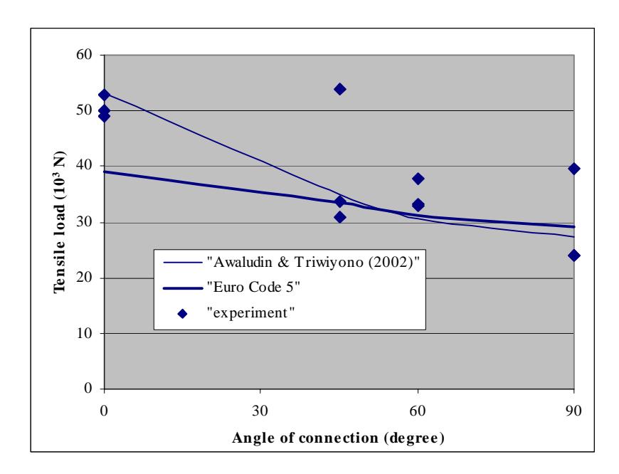
Figure 3. Ultimate tensile load of connection; Experiment and Theoretic
6. Conclusion
- 1. The load-slip curve of split-ring connection is steeper than the load-slip curve of bolted connection.
- 2. The ultimate tensile load of split-ring connection was 30% higher than the bolted connection.
- 3. The displacement of split ring connection was only 67% of the displacement of bolted connection.
- 4. The ultimate tensile load of experiment was scattered closely to the result of Euro Code 5 and Awaludin & Triwiyono (2002).